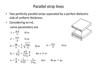
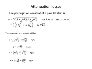
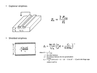
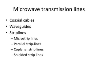
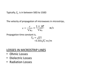
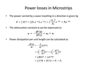
Microwave transmission lines include coaxial cables, waveguides, and strip lines. Strip lines have configurations like microstrip lines, parallel strip lines, coplanar strip lines, and shielded strip lines. Microstrip lines use a conducting strip separated from a ground plane by a dielectric substrate. They have quasi-TEM mode transmission and characteristic impedances typically between 50-150 ohms. Power losses in microstrip lines include ohmic, dielectric, and radiation losses. The document derives equations for microstrip line characteristic impedance and propagation properties, and discusses sources of loss and quality factors.


![Deriving Zo of microstrip lines
Comparison method
Comparing with a wire over ground,
For a wire over ground,
Changes for microstrip lines,
The effective permittivity will be
Other relation will be t/w<0.8
[derived by Assadourian]](https://image.slidesharecdn.com/striplines-100502032146-phpapp02/85/Strip-lines-4-320.jpg)
![• Hence,
Np/m
Np/m
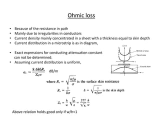
Dielectric loss
from first unit,
σ μ
Attenuation constant, ∝= 2 ε
Phase constant, = μϵ
Here,
σ μ
Dielectric attenuation constant, ∝ =
2 ε
Substituting
We get, [Welch and pratt’s equation]](https://image.slidesharecdn.com/striplines-100502032146-phpapp02/85/Strip-lines-7-320.jpg)