


![REFERENCES
[1] Heat and Mass Transfer by R.K. Rajput (2007)
[2] Isam Jasim Jaber and Ajeet Kumar Rai, “Design and Analysis of IC
Engine Piston and Piston-Ring Using CATIA and ANSYS Software”,
IJMET, Vol.5, 2014.
[3] J.C.Sanders, et al. (1942). Cooling test of an air-cooled engine cylinder
with copper fins on the barrel, NACA Report E-103
[4] Thermal Engineering by Rudramoorthy.
[5] P. Agarwal, et al. (2011). Heat Transfer Simulation by CFD from Fins of
an Air Cooled Motorcycle Engine under Varying Climatic Conditions.
Proceedings of the World Congress on Engineering.
[6] J.A. Paul, et al. (2012). "Experimental and Parametric Study of Extended
Fins in the Optimization of Internal Combustion Engine Cooling Using
CFD." International Journal of Applied Research in Mechanical
Engineering (IJARME) 2(1).
[7] Heat Transfer by PK Nag.
[8] D.G.Kumbhar, et al. (2009). Finite Element Analysis and Experimental
Study of Convective Heat Transfer Augmentation from Horizontal
Rectangular Fin by Triangular Perforations. Proc. of the International
Conference on Advances in Mechanical Engineering.
[9] Denpong Soodphakdee, et al. (2001). "A Comparison of Fin Geometries for
Heatsinks in Laminar Forced Convection Part 1 - Round, Elliptical, and
Plate Fins in Staggered and In-Line Configurations." The International
Journal of Microcircuits and Electronic Packaging 24(1).
[10] Biermann, A. E. and B. Pinkel (1934). Heat Transfer from finned metal
cylinders in an air stream, NACA Report No.488
[11] Shigley, Mechanical Engineering Design, 9
th
editions, McGraw-Hill.
[12] Ajay Raj Singh et al. (2014) “ Design Analysis and Optimisation of three
Aluminium piston alloy using FEA”. IJERA Vol. 4, Issue 1, 2014.
[13] Aditya Kumar Gupta et. al. (2014) “ Design Analysis and Optimisation of IC
engine piston using CAE tool ANSYS”. IJERA, Vol4, Issue 11, 2014.
www.mechieprojects.com
www.mechieprojects.com
www.mechieprojects.com](https://image.slidesharecdn.com/thermo-structural-160603171330/85/IC-Engine-Piston-Design-14-320.jpg)

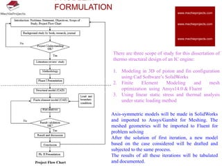
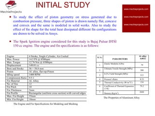
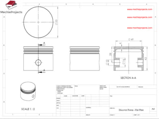
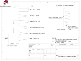
This document outlines the aim, literature review, problem formulation, and initial study of a project on the thermostructural design of a four-stroke internal combustion (IC) engine. The aim is to understand the effects of piston shape and fin parameters on structural strength and heat transfer rate using finite element analysis. An existing 150cc engine will be modeled and optimized. The literature review covers piston and fin design considerations as well as materials. The problem formulation describes modeling pistons and fins in CAD and analyzing them using FEA. The initial study models flat, concave, and convex pistons as well as different fin configurations to analyze stress and heat transfer.


