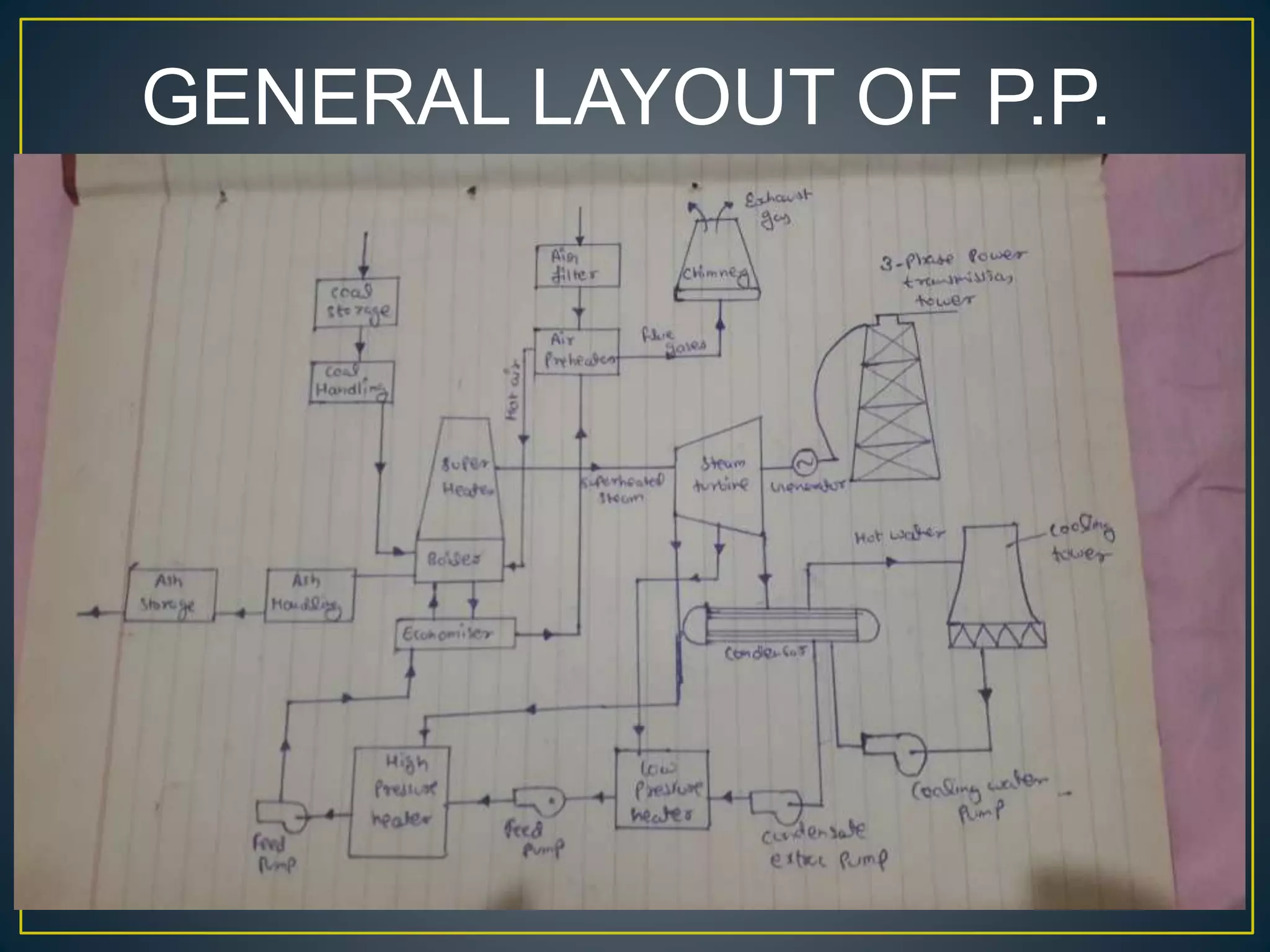
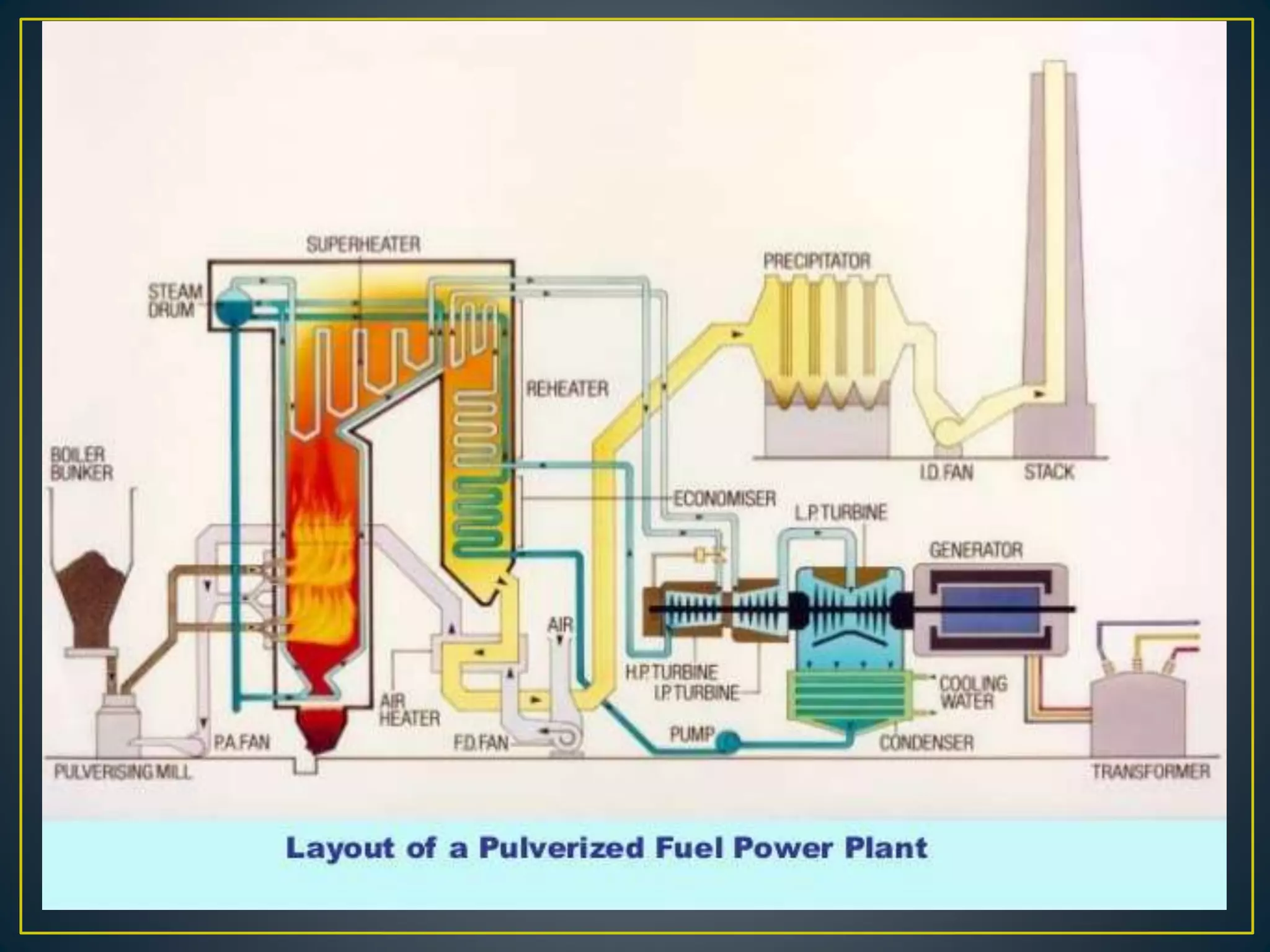
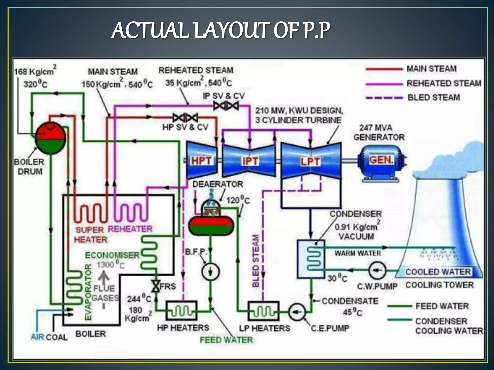
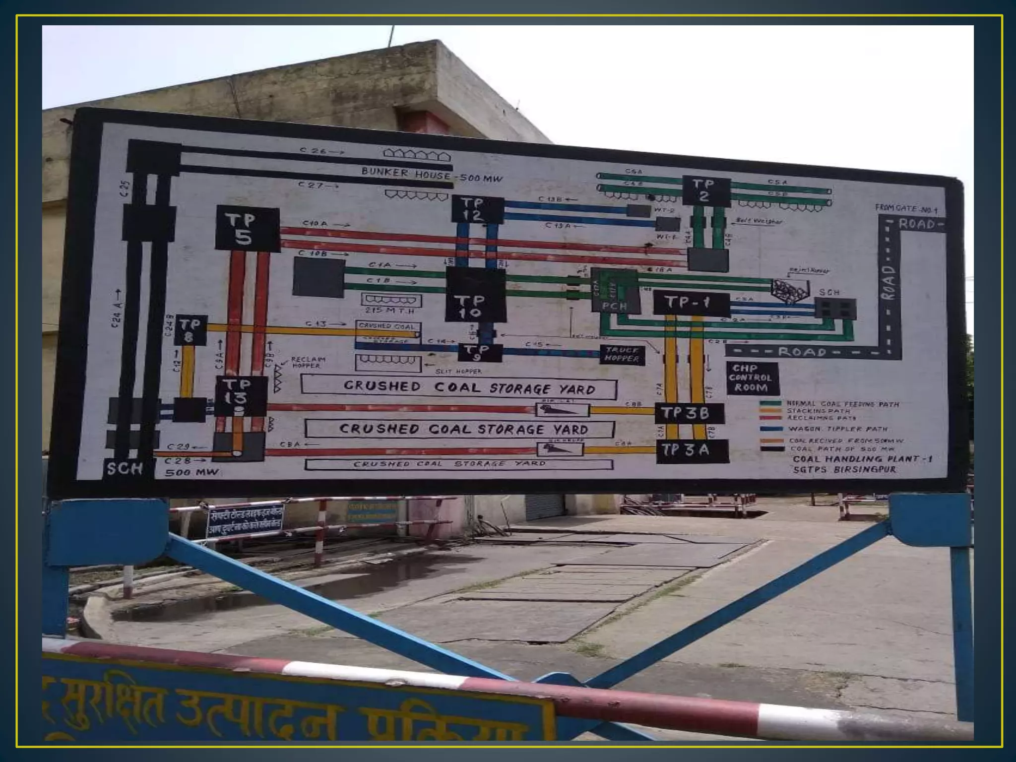
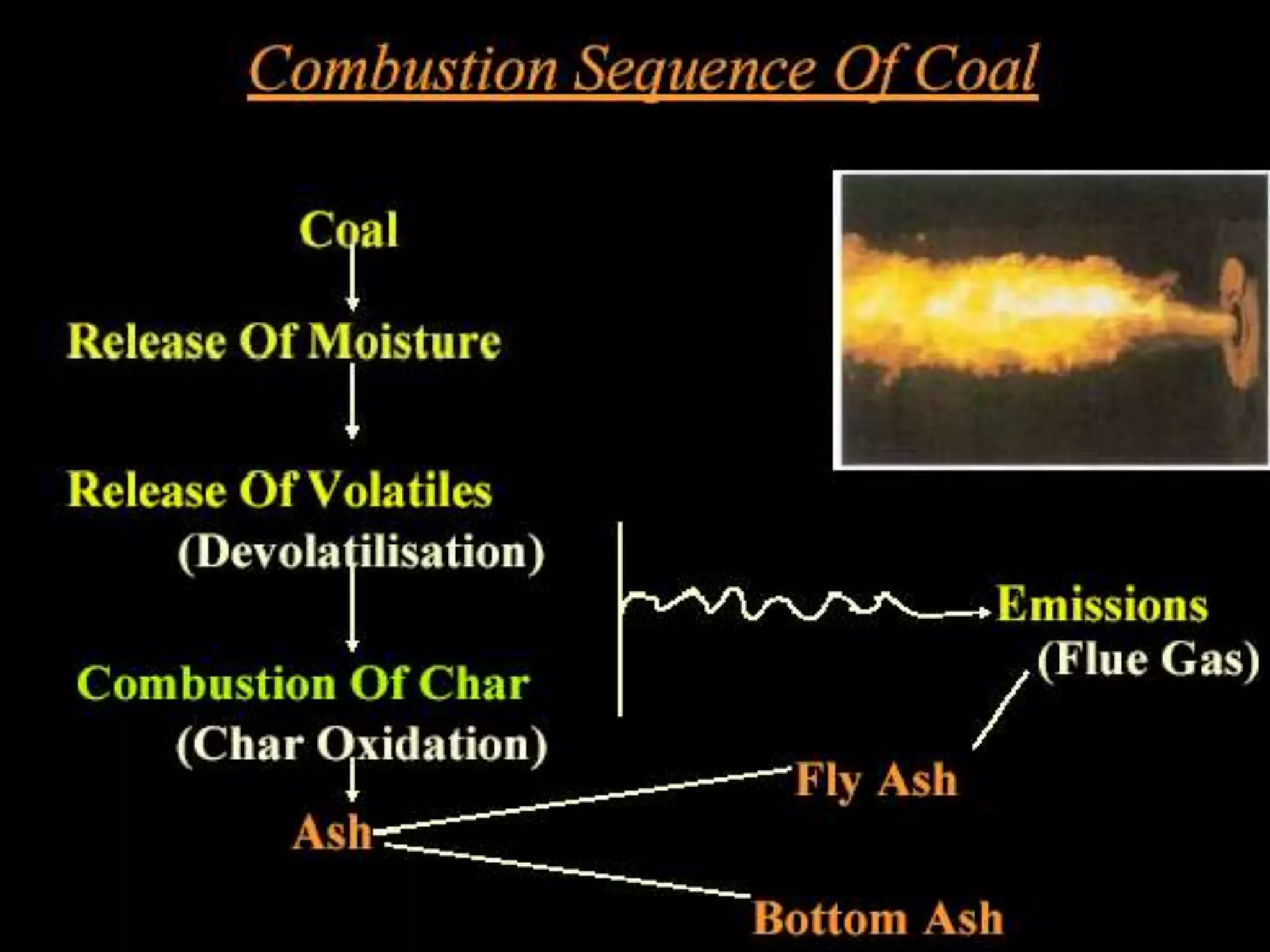
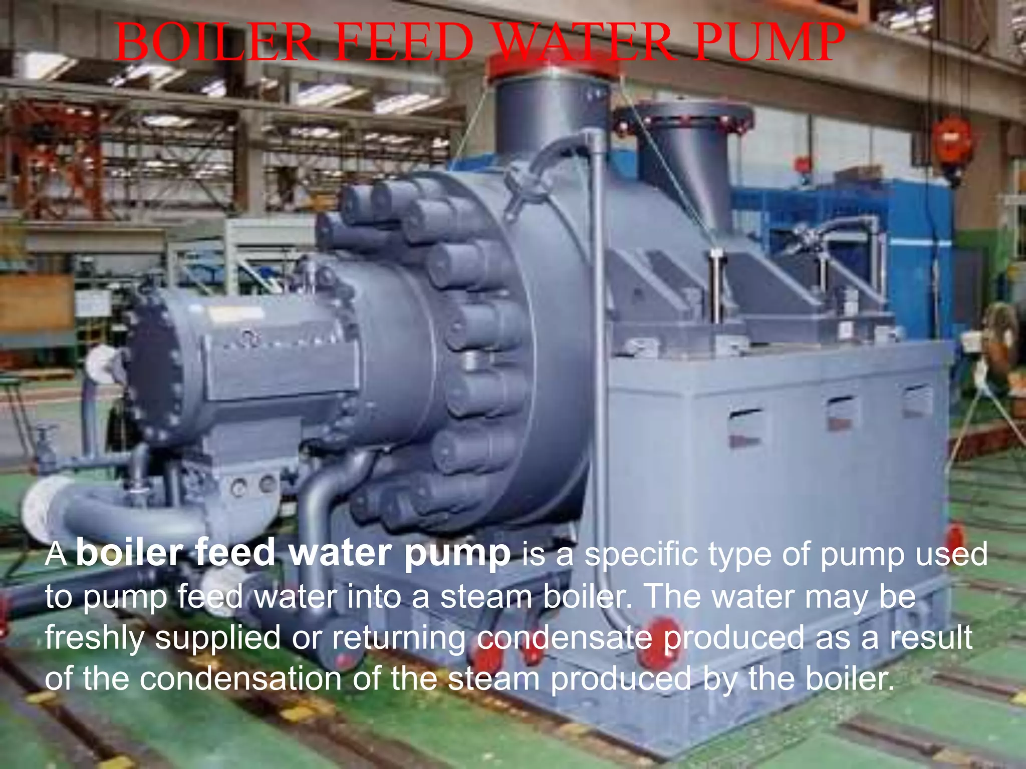
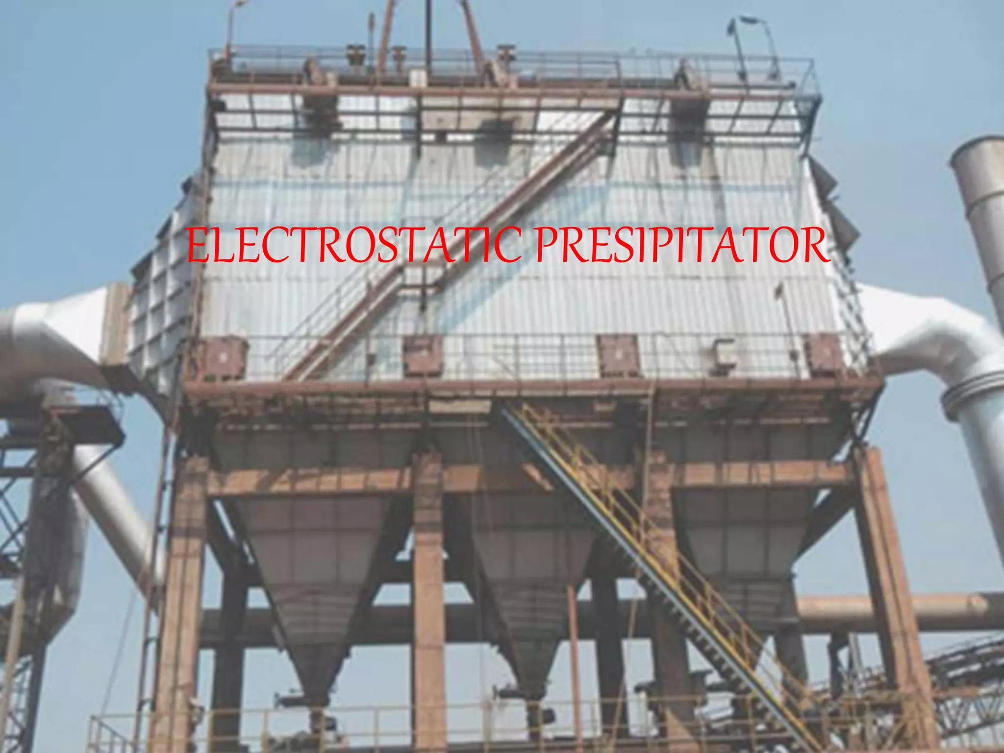
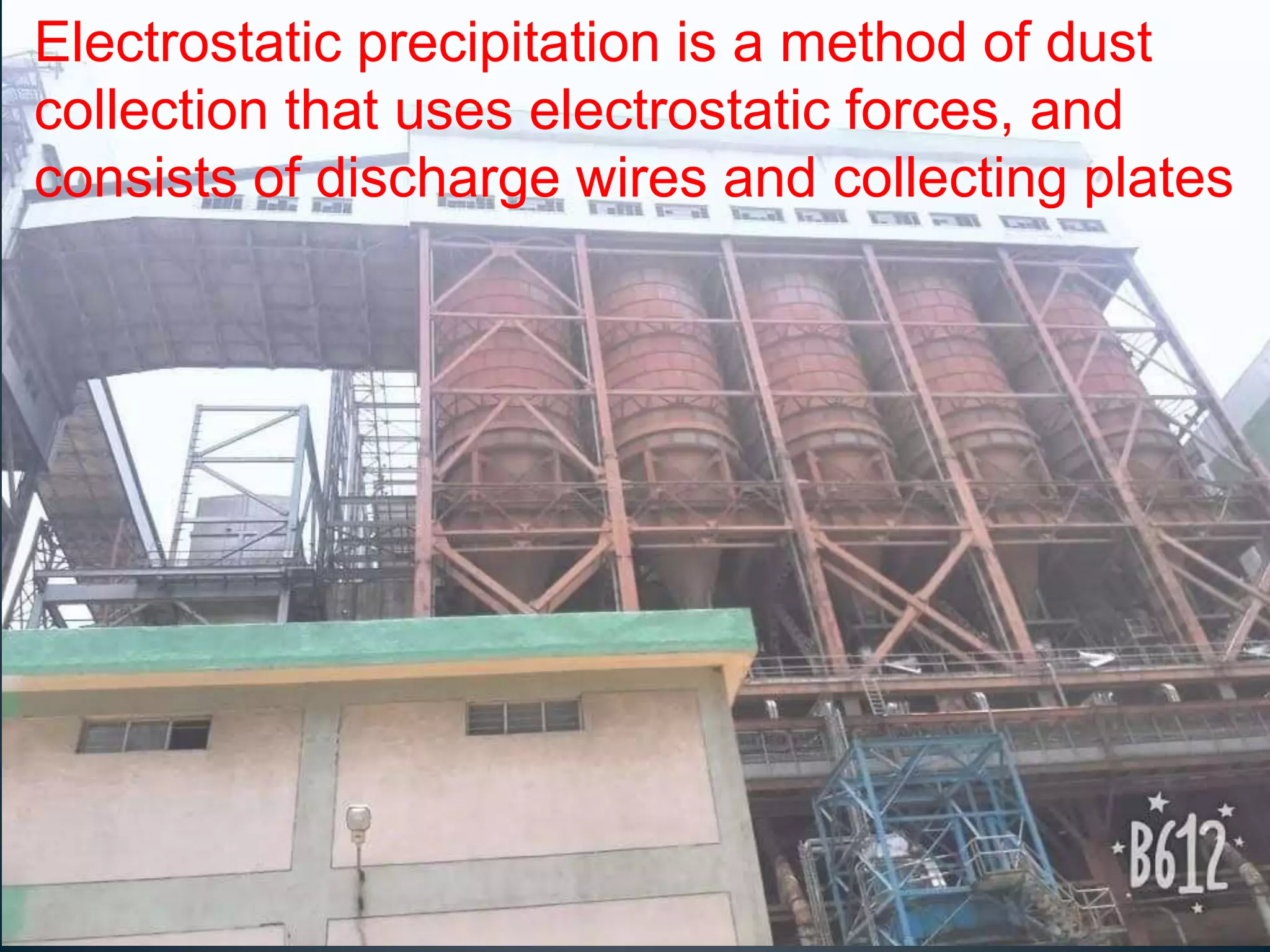
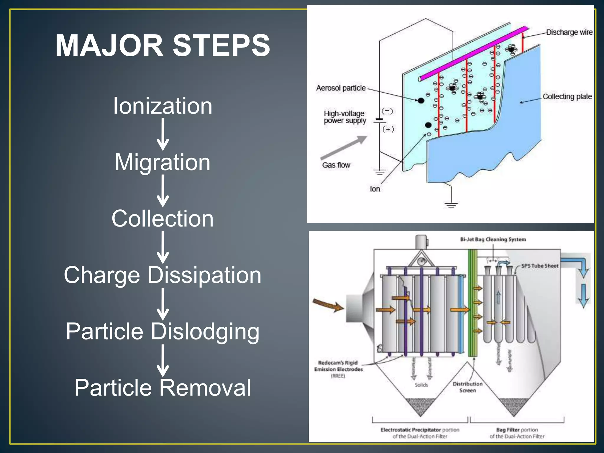
BACHELOR OF ENGINEERING
IN
MECHANICAL ENGINEERING
LOCATION
10 K.M. FROM. BIRSINGHPUR RAILWAY
STATION SITUATED ON BILASPUR KATNI
SECTION OF S.E. RLY
CAPACITY 1340 M.W.
SOURCE OF WATER
JOHILA DAM; AREA 1810 HECTARE ON
JOHILA RIVER
DAM CAPACITY 171 MILION CUBIC METER
FUEL PRIMARY FUEL - COAL
SECONDARY FUEL - FO/LDO
COAL SOURCE SOUTH ESTERN COAL FIELD LIMITED
COAL AREA KOREA REWA AND KORBA
MODE OF TRANSPORT RAIL
COAL LINKAGE 63.60 LMT (appx.) PER ANNUM (2007-08)
POWER EVACUATION 220 K.V.
LINE
BIRSINGHPUR REWA SATNA
BIRSINGHPUR KATNI (2)
BIRSINGHPUR AMK (2)
Sanjay Gandhi Thermal Power Station, Birsinghpur:
UNITS
CAPACITY
MW
COMMISSIONI
NG DATES
MAKE TG SET MAKE BOILER
Unit I 210 26-03-1993 BHEL ABL
Unit II 210 27-03-1994 BHEL ABL
Unit III 210 28-02-1999 BHEL ABL
Unit IV 210 23-11-1999 BHEL ABL
Unit V 500 18-06-2007 BHEL BHEL
“IMPORTANT FACT”
1.The capacity of 4×210 MW in 20.16 million unit per
day.
2.Boiler can be make or installed in ABB,ABL
Company in Durgapur at West Bengal and Turbine
can be installed in BHEL.
3.The coal is sourced from Lorsen and Turbo in
Kolkata.
4.14500 million ton coal is grinded in everyday and
2000 million ton water is used in everyday in this plant.
THREE MAJOR INPUTS TO POWER STAT
1) Water :- Water has been taken from near by JOHILA RIVER . The
clear water is sent to water treatment plant, cooling water system
and service water system. The water is de-mineralized (DM) by
water treatment plant. The DM water is stored in condensate storage
tanks from where it is used in boiler
2) Fuel Oil :- The fuel oil used is of two types:
(a) Low sulphur high stock oil (LSHS)
(b) High speed diesel oil (HSD)
The high speed diesel oil reaches the power station through the lorry
tankers. The oil is stored in large tanks for the future use in the boiler.
3) COAL :- The coal reaches the plant in the railways wagons. The
unloading of coal is done mechanically by tilting the wagons by
tippler. The coal is sent to the coal storage yard through the conveyor
belts. The crushed coal from store is sent to the mill bunkers through
conveyor belts.
Pulverized coal obtained from coal mill can not be burnt directly.
GENERAL LAYOUT OF P.P.
ACTUAL LAYOUT OF P.P
THERMAL POWER PLANT
A thermal power plant is a power plant is a power plant in
which the prime mover is stream. Water is heated, turns into
stream & spine a turbine which drives and electric generator.
After it passes through the turbine the steam is condense in a
condenser & recycle to where it was heated, this is known as
RANKINE CYCLE.
WORKING STAGES OF THERMAL POWER
PLANT
STAGE 1:- D-mineralized PLANT (DM)
STAGE 2:- Coal Handling Plant (CHP)
STAGE 3:- Boiler Section
STAGE 4:- Turbine Section
STAGE 5:- Ash Handling Plant (AHP)
D-mineralized PLANT (DM
DEMINERALISZATION PLANT:
Demineralization is the process of
removing mineral salts from water by using the ion
exchange process.
In the DM Plant the water is D-mineralized. The water
is used for steam generation is must be free from
colloidal & dissolved impurities. All the colloidal
impurities are removed in the WATER CLARIFIER.
Then the supplied to the DM Plant.
Water clarifier – DM PLANT
Principle :
Raw water is passed via two small polystyrene
bead
filled (ion exchange resins) beds.
While the cation’s get exchanged with hydrogen
ions in
first bed.
The anions are exchanged with hydroxyl ions, in
the
second one.
PROCESS OF DM PLANT
filter AC filter Cation
Tank
Gas towerAnion tank
At last it passed in the mixed bed all the minerals
present in the water removed & the water is
completely free from minerals.
Coal Handling Plant (CHP)
INPLANT COAL HANDLING
COAL DELIVERY
ROAD RAILS
Unloading
Out Door Storage
Preparation
Transfer
Covered Storage
In Plant Handling
Furnace Fire
Weighting
InPlantHandling
Car shakers, rotary car dampers, unloading
bridges, self unloading ship, lifts truck &
bucket.
Bulldozers, cranes, scrapers,
tramways, conveyers.
Crushers, sizers, etc.
Belt conveyers, Screw conveyers,
Buckets elevator, flight conveyers.
Bins, bunkers, gates & valves.
Scales, coal meters, samplers.
COAL MILL Coal mills are mainly used to cursed the coal. It
cursed the coal in powder form. The powder form o coal is
known as scream. In the Unit-1, 6 coal mills are present in the
unit.
WORKING:
Coal coming from CHM to coal
bunker, which in small feed able
parts. RC feeder control the feeds of
the coal in the mill, three roller
crushed the coal like as scream (as a
powder form). Hot air supplied by PA
fan help to crush the coal & cold air
maintain temp. Gear present at the
bottom is prevent the jamming by
giving motion to the powder coal.PA
fan maintain sufficient transfer
pressure & the coal from 4 outlet pipe
is given to the furnace.
COAL PULVARIZER
BOILER
Boiler means any closed vessel exceeding 22.75 liters (five
gallons) in capacity which is used expressly for generating
steam under pressure and includes any mounting or other
fitting attached to such vessel, which is wholly or partly under
pressure when steam is shut off:
Classification of PF Boilers
Based on Operating Pressure :-
• Sub-Critical: < Critical Pr. 221.2 Bar
• Super critical: > Critical Pr. 221.2 Bar
• Ultra-super critical > Pr. > 300 Bar
Based on Types of
Circulation:-
• Natural Circulation Boiler
• Assisted circulation Boiler
• Once through Boiler
Based on Types of firing:-
• Wall fired: Front / Opposed
• Corner fired: Tangential
• Down-shot fired : Single / Double
Tangential firing is a method of firing a fuel to heat air
in thermal power stations. The flame envelope rotates
ensuring thorough mixing within the furnace, providing
complete combustion and uniform heat distribution.
PROCESS OF BOILER PLANT
BOILER MOUNTING:
BOILER MOUNTINGS are the components generally
mounted on the surface of the boiler to have safety
during operation. These are the essential parts of the
boiler, without which the boiler operation is not
possible. The following are the important mountings of
the boiler:
Water level indicator
Safety valve
Pressure gauge
Steam stop valve
Feed check valve
Main hole
BOILER ACCESSORIES :-
These are those devices which are installed
with a boiler and its neighboring area to increase the efficiency
of the boiler. These are not the essential part of the boiler and
thus without installing these devices, the boiler operation can
be accomplished though at a lower efficiency.
•Feed water pump
•Injector
•Pressure reducing valve
•Economizer
•Air pre heater
•Super heater
BOILER EMERGENCY
A) FAN EMERGENCY ( ID, FD,
PA)
B) APH EMERGENCY
C) MILL EMERGENCY
D) BFP EMERGENCY
D) BOILER TUBE LEAKAGE
E) MFT (MASTER FUEL TRIP)
Boiler performance
Evaporative capacity:-
can be expressed in terms of:
a) kg of steam/hr.
b) kg of hour/hr/m2 of heating surface
c) kg of steam/kg of fuel fired
Boiler efficiency
• Ratio of heat actually utilized in the generator to
the heat supplied by the fuel.
Efficiency= mw(h-hf)/C
Where C is the calorific value
TURBINE
The steam turbine is a prime mover that
converts the stored mechanical energy in steam
into rotational mechanical energy. A turbine pair
consists of a ring of fixed blade and a ring of
moving blades.
 The turbine consists of three casings, high,
intermediate and low pressure.
 ROTORS, BEARING AND TURNING GEAR: All the rotors
including the rotor of the generator are mutually connected
by means of rigid coupling. The critical speed of the turbine
rotors is best noticed between 1900-2350rpm. Double
sided axial thrust bearing is located in between HP & MP
casings.
Differential expansions are measured at 3 points:-
on the front bearing pedestal
on the pedestal between MP & HP parts
and between LP & Generator to access relative expansion
of stator and rotor.
There are SIX radial bearings on which rotor is
supported. With proper expansion of all turbine
parts, the load sharing is equal in all bearings.
The bearings are placed in:
1) HP front standard
2) between HP & IP.
3) both side of LP
3) both side of generator
SUPPORT OF RADIAL BEARING
High Pressure (HP) Turbine
Inlet Temperature 535oC.
Outlet Temperature 343oC.
Inlet pressure 150 Kg/cm2 (147.1 bar).
Outlet Pressure 49 Kg/cm2 (48.052 bar).
INTERMIDITE PRESSURE
TURBINE
Inlet Temperature 535oC
Outlet Temperature 340oC
Inlet pressure 37 Kg/cm2 (36.28 Bar)
Outlet Pressure 7 Kg/cm2 (6.864 Bar)
LOW PRESSURE TURBINE
Inlet Temperature 360oC
Outlet Temperature 45oC
Inlet pressure 7 Kg/cm2 (6.864 Bar)
Outlet Pressure 0.85 Kg/cm2 (0.833 Bar)
GENERATO
Generators
Electric generators transform kinetic energy into
electricity. This is the most used form for generating
electricity and is based on Faraday's law. It can be seen
experimentally by rotating a magnet within closed loops
of a conducting material (e.g. copper wire). Almost all
commercial electrical generation is done using
electromagnetic induction, in which mechanical
energy forces a generator to rotate.
CONDENSER
The steam after working in the turbine is
condensed in condenser in each unit installed
below the LP exhaust.In thermal power plants, the purpose of a
surface condenser is to condense the exhaust
steam from a steam turbine to obtain
maximum efficiency, and also to convert the
turbine exhaust steam into pure water (referred
to as steam condensate) so that it may be
reused in the steam generator or boiler as boiler
feed water.
LOW PRESSURE HEATER
Low pressure (LP) feed
water heaters are
basically simple
straightforward 'tube
and shell' heat
exchangers, with the
condensate passing
through the tubes and
the bled-steam being
admitted to the shell.
Deaerator
A deaerator is a device that is widely used for the
removal of oxygen and other dissolved gases from
the feed water to steam-generating boilers.
BOILER FEED WATER PUMP
A boiler feed water pump is a specific type of pump used
to pump feed water into a steam boiler. The water may be
freshly supplied or returning condensate produced as a result
of the condensation of the steam produced by the boiler.
HIGH PRESSURE HEATER
The high-pressure feed heater is a heat exchanger of
the shell and tube type which further heats the
feedwater before entry to the boiler. Further heat may
be added to the feed water without its becoming
steam since its pressure has now been raised by the
ASH HANDLING PLANT
Ash handling systems are required for
removal of bottom ash and fly ash from coal
fired boilers.
TYPES OF
ASHES
BOTTOM
ASH
FLY ASH
Fly Ash
• Residual of Coal Combustion
• Comprises of fine particles that rises with Flue Gases
• All types of fly ash includes substantial amounts of
silicon dioxide and Calcium Oxide
• Size range – from 0.5 μm to 100 μm
Bottom Ash
• Non- Combustible Part of Combustion
• Comprises traces of combustibles embedded in
forming clinkers and sticking to hot side walls of a coal-
burning furnace
• The clinkers fall by themselves into the water or
sometimes by poking manually, and get cooled
• May be used as an aggregate in road construction
and concrete
Handling Equipment Should
Perform The Following
Functions:
• Capital investment, operating and maintenance
charges of the equipment should be low.
• It should be able to handle large quantities of ash.
• Clinkers, soot, dust etc. create troubles, the
equipment should be able to handle them smoothly.
• The equipment should be corrosion and wear
resistant.
Various types of handling system
Wheel Barrows (Manual Handling)
Mechanical Handling
 bucket elevator
 bucket conveyor
 centrifugal discharge bucket elevator
Steam jet system
Pneumatic-conveyor system
hydraulic or gravity system
ELECTROSTATIC PRESIPITATOR
Electrostatic precipitation is a method of dust
collection that uses electrostatic forces, and
consists of discharge wires and collecting plates
WORKING
A high voltage is applied to the discharge wires to form
an electrical field between the wires and the collecting
plates, and also ionizes the gas around the discharge
wires to supply ions.
When gas that contains an aerosol (dust, mist) flows
between the collecting plates and the discharge wires,
the aerosol particles in the gas are charged by the ions.
The Coulomb force caused by the electric field causes
the charged particles to be collected on the collecting
plates, and the gas is purified.
This is the principle of electrostatic precipitation, and
Electrostatic precipitator apply this principle on an
industrial scale.
MAJOR STEPS
Ionization
Migration
Collection
Charge Dissipation
Particle Dislodging
Particle Removal
CHIMNEY
The gases produced due to burning of coal are
comes out from chimney. The height of chimney is
designed with respect to the boiler layout. The temp.
is also maintained in the chimney. It is not more than
120 c. If it more than 120 c, then boiler will be
corrupt..
FANS USED IN POWER PLANTS:
A fan can be considered a mechanical
device that moves a volume of fluid
such as air, gas, or vapor through a
pressure driven flow. Large capacity fan
units typically consist of a bladed,
rotating impeller enclosed in a
stationary casing
There are three main types of fans used
in fossil power plants.
Forced draft fans,
Induced draft fans,
1) P.A. FANS:
These fans are used to supply the hot air
in order to dry powdered coal. To transport
pulverized coal to the furnace the speed of PA fans
1400 rpm and they supply 83800 m3 per hour.
These are installed either side of boiler
2) F.D FANS:
These are used to take air from the
atmosphere at ambient temp. to supply it to the furnace for
combustion purpose.
Speed is about 990 r.p.m and it handles 203760 m3 of air
per hour. These are installed either side of boiler
3) INDUCED DRAFT FANS (ID FANS)
These are used to suck the flues gases
from the furnace and through it into the stack so as to dispose
them off into the atmosphere. It handles flash laden gases at
a temp. Of 125 to 200degrees Its speed is around 970 rpm
and it handles 453600 m3 of air per hour.
These are installed at the outlet of electrostatic precipitator.
I.D FAN P.A FAN F.D FAN
COOLING TOWER
A cooling tower is a specialized heat exchanger in
which air and water are brought into direct contact with each
other in order to reduce the water's temperature. As this
occurs, a small volume of water is evaporated, reducing the
temperature of the water being circulated through the tower.
TYPES OF COOLING
TOWERS:-
1) INDUCED DRAFT
2) FORCED DRAFT
THANKYOU

Presentation on THERMAL POWER PLANT

  • 1.
  • 2.
    LOCATION 10 K.M. FROM.BIRSINGHPUR RAILWAY STATION SITUATED ON BILASPUR KATNI SECTION OF S.E. RLY CAPACITY 1340 M.W. SOURCE OF WATER JOHILA DAM; AREA 1810 HECTARE ON JOHILA RIVER DAM CAPACITY 171 MILION CUBIC METER FUEL PRIMARY FUEL - COAL SECONDARY FUEL - FO/LDO COAL SOURCE SOUTH ESTERN COAL FIELD LIMITED COAL AREA KOREA REWA AND KORBA MODE OF TRANSPORT RAIL COAL LINKAGE 63.60 LMT (appx.) PER ANNUM (2007-08) POWER EVACUATION 220 K.V. LINE BIRSINGHPUR REWA SATNA BIRSINGHPUR KATNI (2) BIRSINGHPUR AMK (2) Sanjay Gandhi Thermal Power Station, Birsinghpur:
  • 3.
    UNITS CAPACITY MW COMMISSIONI NG DATES MAKE TGSET MAKE BOILER Unit I 210 26-03-1993 BHEL ABL Unit II 210 27-03-1994 BHEL ABL Unit III 210 28-02-1999 BHEL ABL Unit IV 210 23-11-1999 BHEL ABL Unit V 500 18-06-2007 BHEL BHEL
  • 4.
    “IMPORTANT FACT” 1.The capacityof 4×210 MW in 20.16 million unit per day. 2.Boiler can be make or installed in ABB,ABL Company in Durgapur at West Bengal and Turbine can be installed in BHEL. 3.The coal is sourced from Lorsen and Turbo in Kolkata. 4.14500 million ton coal is grinded in everyday and 2000 million ton water is used in everyday in this plant.
  • 5.
    THREE MAJOR INPUTSTO POWER STAT 1) Water :- Water has been taken from near by JOHILA RIVER . The clear water is sent to water treatment plant, cooling water system and service water system. The water is de-mineralized (DM) by water treatment plant. The DM water is stored in condensate storage tanks from where it is used in boiler 2) Fuel Oil :- The fuel oil used is of two types: (a) Low sulphur high stock oil (LSHS) (b) High speed diesel oil (HSD) The high speed diesel oil reaches the power station through the lorry tankers. The oil is stored in large tanks for the future use in the boiler. 3) COAL :- The coal reaches the plant in the railways wagons. The unloading of coal is done mechanically by tilting the wagons by tippler. The coal is sent to the coal storage yard through the conveyor belts. The crushed coal from store is sent to the mill bunkers through conveyor belts. Pulverized coal obtained from coal mill can not be burnt directly.
  • 6.
  • 8.
  • 10.
    THERMAL POWER PLANT Athermal power plant is a power plant is a power plant in which the prime mover is stream. Water is heated, turns into stream & spine a turbine which drives and electric generator. After it passes through the turbine the steam is condense in a condenser & recycle to where it was heated, this is known as RANKINE CYCLE.
  • 12.
    WORKING STAGES OFTHERMAL POWER PLANT STAGE 1:- D-mineralized PLANT (DM) STAGE 2:- Coal Handling Plant (CHP) STAGE 3:- Boiler Section STAGE 4:- Turbine Section STAGE 5:- Ash Handling Plant (AHP)
  • 13.
  • 14.
    DEMINERALISZATION PLANT: Demineralization isthe process of removing mineral salts from water by using the ion exchange process. In the DM Plant the water is D-mineralized. The water is used for steam generation is must be free from colloidal & dissolved impurities. All the colloidal impurities are removed in the WATER CLARIFIER. Then the supplied to the DM Plant. Water clarifier – DM PLANT
  • 15.
    Principle : Raw wateris passed via two small polystyrene bead filled (ion exchange resins) beds. While the cation’s get exchanged with hydrogen ions in first bed. The anions are exchanged with hydroxyl ions, in the second one.
  • 16.
    PROCESS OF DMPLANT filter AC filter Cation Tank Gas towerAnion tank At last it passed in the mixed bed all the minerals present in the water removed & the water is completely free from minerals.
  • 17.
  • 18.
    INPLANT COAL HANDLING COALDELIVERY ROAD RAILS Unloading Out Door Storage Preparation Transfer Covered Storage In Plant Handling Furnace Fire Weighting InPlantHandling Car shakers, rotary car dampers, unloading bridges, self unloading ship, lifts truck & bucket. Bulldozers, cranes, scrapers, tramways, conveyers. Crushers, sizers, etc. Belt conveyers, Screw conveyers, Buckets elevator, flight conveyers. Bins, bunkers, gates & valves. Scales, coal meters, samplers.
  • 19.
    COAL MILL Coalmills are mainly used to cursed the coal. It cursed the coal in powder form. The powder form o coal is known as scream. In the Unit-1, 6 coal mills are present in the unit. WORKING: Coal coming from CHM to coal bunker, which in small feed able parts. RC feeder control the feeds of the coal in the mill, three roller crushed the coal like as scream (as a powder form). Hot air supplied by PA fan help to crush the coal & cold air maintain temp. Gear present at the bottom is prevent the jamming by giving motion to the powder coal.PA fan maintain sufficient transfer pressure & the coal from 4 outlet pipe is given to the furnace.
  • 21.
  • 22.
  • 23.
    Boiler means anyclosed vessel exceeding 22.75 liters (five gallons) in capacity which is used expressly for generating steam under pressure and includes any mounting or other fitting attached to such vessel, which is wholly or partly under pressure when steam is shut off: Classification of PF Boilers Based on Operating Pressure :- • Sub-Critical: < Critical Pr. 221.2 Bar • Super critical: > Critical Pr. 221.2 Bar • Ultra-super critical > Pr. > 300 Bar
  • 24.
    Based on Typesof Circulation:- • Natural Circulation Boiler • Assisted circulation Boiler • Once through Boiler Based on Types of firing:- • Wall fired: Front / Opposed • Corner fired: Tangential • Down-shot fired : Single / Double
  • 25.
    Tangential firing isa method of firing a fuel to heat air in thermal power stations. The flame envelope rotates ensuring thorough mixing within the furnace, providing complete combustion and uniform heat distribution.
  • 27.
  • 28.
    BOILER MOUNTING: BOILER MOUNTINGSare the components generally mounted on the surface of the boiler to have safety during operation. These are the essential parts of the boiler, without which the boiler operation is not possible. The following are the important mountings of the boiler: Water level indicator Safety valve Pressure gauge Steam stop valve Feed check valve Main hole
  • 29.
    BOILER ACCESSORIES :- Theseare those devices which are installed with a boiler and its neighboring area to increase the efficiency of the boiler. These are not the essential part of the boiler and thus without installing these devices, the boiler operation can be accomplished though at a lower efficiency. •Feed water pump •Injector •Pressure reducing valve •Economizer •Air pre heater •Super heater
  • 30.
    BOILER EMERGENCY A) FANEMERGENCY ( ID, FD, PA) B) APH EMERGENCY C) MILL EMERGENCY D) BFP EMERGENCY D) BOILER TUBE LEAKAGE E) MFT (MASTER FUEL TRIP)
  • 31.
    Boiler performance Evaporative capacity:- canbe expressed in terms of: a) kg of steam/hr. b) kg of hour/hr/m2 of heating surface c) kg of steam/kg of fuel fired
  • 32.
    Boiler efficiency • Ratioof heat actually utilized in the generator to the heat supplied by the fuel. Efficiency= mw(h-hf)/C Where C is the calorific value
  • 33.
  • 34.
    The steam turbineis a prime mover that converts the stored mechanical energy in steam into rotational mechanical energy. A turbine pair consists of a ring of fixed blade and a ring of moving blades.
  • 35.
     The turbineconsists of three casings, high, intermediate and low pressure.  ROTORS, BEARING AND TURNING GEAR: All the rotors including the rotor of the generator are mutually connected by means of rigid coupling. The critical speed of the turbine rotors is best noticed between 1900-2350rpm. Double sided axial thrust bearing is located in between HP & MP casings. Differential expansions are measured at 3 points:- on the front bearing pedestal on the pedestal between MP & HP parts and between LP & Generator to access relative expansion of stator and rotor.
  • 36.
    There are SIXradial bearings on which rotor is supported. With proper expansion of all turbine parts, the load sharing is equal in all bearings. The bearings are placed in: 1) HP front standard 2) between HP & IP. 3) both side of LP 3) both side of generator SUPPORT OF RADIAL BEARING
  • 39.
    High Pressure (HP)Turbine Inlet Temperature 535oC. Outlet Temperature 343oC. Inlet pressure 150 Kg/cm2 (147.1 bar). Outlet Pressure 49 Kg/cm2 (48.052 bar).
  • 40.
    INTERMIDITE PRESSURE TURBINE Inlet Temperature535oC Outlet Temperature 340oC Inlet pressure 37 Kg/cm2 (36.28 Bar) Outlet Pressure 7 Kg/cm2 (6.864 Bar)
  • 41.
    LOW PRESSURE TURBINE InletTemperature 360oC Outlet Temperature 45oC Inlet pressure 7 Kg/cm2 (6.864 Bar) Outlet Pressure 0.85 Kg/cm2 (0.833 Bar)
  • 43.
  • 44.
    Generators Electric generators transformkinetic energy into electricity. This is the most used form for generating electricity and is based on Faraday's law. It can be seen experimentally by rotating a magnet within closed loops of a conducting material (e.g. copper wire). Almost all commercial electrical generation is done using electromagnetic induction, in which mechanical energy forces a generator to rotate.
  • 46.
    CONDENSER The steam afterworking in the turbine is condensed in condenser in each unit installed below the LP exhaust.In thermal power plants, the purpose of a surface condenser is to condense the exhaust steam from a steam turbine to obtain maximum efficiency, and also to convert the turbine exhaust steam into pure water (referred to as steam condensate) so that it may be reused in the steam generator or boiler as boiler feed water.
  • 47.
    LOW PRESSURE HEATER Lowpressure (LP) feed water heaters are basically simple straightforward 'tube and shell' heat exchangers, with the condensate passing through the tubes and the bled-steam being admitted to the shell.
  • 48.
    Deaerator A deaerator isa device that is widely used for the removal of oxygen and other dissolved gases from the feed water to steam-generating boilers.
  • 49.
    BOILER FEED WATERPUMP A boiler feed water pump is a specific type of pump used to pump feed water into a steam boiler. The water may be freshly supplied or returning condensate produced as a result of the condensation of the steam produced by the boiler.
  • 50.
    HIGH PRESSURE HEATER Thehigh-pressure feed heater is a heat exchanger of the shell and tube type which further heats the feedwater before entry to the boiler. Further heat may be added to the feed water without its becoming steam since its pressure has now been raised by the
  • 51.
  • 52.
    Ash handling systemsare required for removal of bottom ash and fly ash from coal fired boilers. TYPES OF ASHES BOTTOM ASH FLY ASH
  • 53.
    Fly Ash • Residualof Coal Combustion • Comprises of fine particles that rises with Flue Gases • All types of fly ash includes substantial amounts of silicon dioxide and Calcium Oxide • Size range – from 0.5 μm to 100 μm Bottom Ash • Non- Combustible Part of Combustion • Comprises traces of combustibles embedded in forming clinkers and sticking to hot side walls of a coal- burning furnace • The clinkers fall by themselves into the water or sometimes by poking manually, and get cooled • May be used as an aggregate in road construction and concrete
  • 54.
    Handling Equipment Should PerformThe Following Functions: • Capital investment, operating and maintenance charges of the equipment should be low. • It should be able to handle large quantities of ash. • Clinkers, soot, dust etc. create troubles, the equipment should be able to handle them smoothly. • The equipment should be corrosion and wear resistant.
  • 55.
    Various types ofhandling system Wheel Barrows (Manual Handling) Mechanical Handling  bucket elevator  bucket conveyor  centrifugal discharge bucket elevator Steam jet system Pneumatic-conveyor system hydraulic or gravity system
  • 56.
  • 57.
    Electrostatic precipitation isa method of dust collection that uses electrostatic forces, and consists of discharge wires and collecting plates
  • 58.
    WORKING A high voltageis applied to the discharge wires to form an electrical field between the wires and the collecting plates, and also ionizes the gas around the discharge wires to supply ions. When gas that contains an aerosol (dust, mist) flows between the collecting plates and the discharge wires, the aerosol particles in the gas are charged by the ions. The Coulomb force caused by the electric field causes the charged particles to be collected on the collecting plates, and the gas is purified. This is the principle of electrostatic precipitation, and Electrostatic precipitator apply this principle on an industrial scale.
  • 59.
  • 60.
  • 61.
    The gases produceddue to burning of coal are comes out from chimney. The height of chimney is designed with respect to the boiler layout. The temp. is also maintained in the chimney. It is not more than 120 c. If it more than 120 c, then boiler will be corrupt..
  • 62.
    FANS USED INPOWER PLANTS: A fan can be considered a mechanical device that moves a volume of fluid such as air, gas, or vapor through a pressure driven flow. Large capacity fan units typically consist of a bladed, rotating impeller enclosed in a stationary casing There are three main types of fans used in fossil power plants. Forced draft fans, Induced draft fans,
  • 63.
    1) P.A. FANS: Thesefans are used to supply the hot air in order to dry powdered coal. To transport pulverized coal to the furnace the speed of PA fans 1400 rpm and they supply 83800 m3 per hour. These are installed either side of boiler 2) F.D FANS: These are used to take air from the atmosphere at ambient temp. to supply it to the furnace for combustion purpose. Speed is about 990 r.p.m and it handles 203760 m3 of air per hour. These are installed either side of boiler
  • 64.
    3) INDUCED DRAFTFANS (ID FANS) These are used to suck the flues gases from the furnace and through it into the stack so as to dispose them off into the atmosphere. It handles flash laden gases at a temp. Of 125 to 200degrees Its speed is around 970 rpm and it handles 453600 m3 of air per hour. These are installed at the outlet of electrostatic precipitator. I.D FAN P.A FAN F.D FAN
  • 65.
  • 66.
    A cooling toweris a specialized heat exchanger in which air and water are brought into direct contact with each other in order to reduce the water's temperature. As this occurs, a small volume of water is evaporated, reducing the temperature of the water being circulated through the tower. TYPES OF COOLING TOWERS:- 1) INDUCED DRAFT 2) FORCED DRAFT
  • 67.