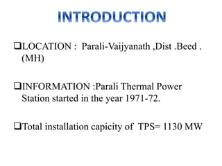
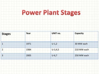
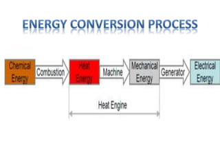
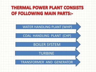
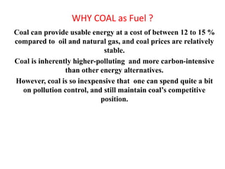
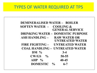
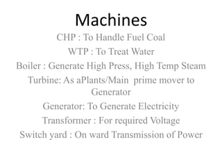
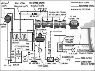
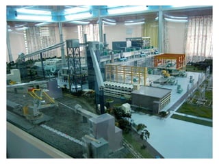
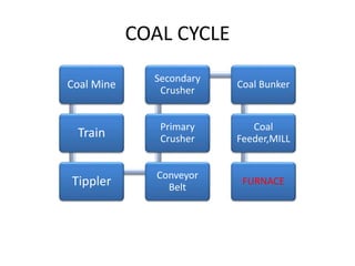
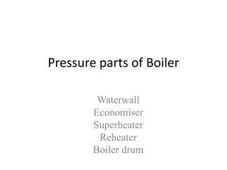
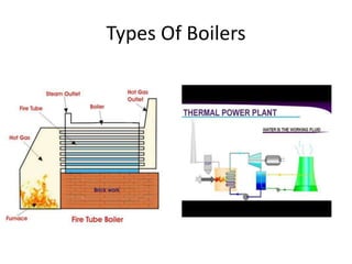
WEL-COME
BY
NIRAJ J. MESHRAM
MAHENDRA S. MAGRE
VISHAL P. TAKLE
NIKHILESH G. VAIDYA
KAPIL J. CHINCHOLE
THERMAL POWER
STATION
LOCATION : Parali-Vaijyanath ,Dist .Beed .
(MH)
INFORMATION :Parali Thermal Power
Station started in the year 1971-72.
Total installation capicity of TPS= 1130 MW
Stages Year UNIT no. Capacity
1 1971 U-1,2 30 MW each
2 1984 U-3,4,5 210 MW each
3 2005 U-6,7 250 MW each
All power plants convert some form of easily and
naturally available energy in to electrical energy. In
thermal power plant, Water is the working fluid. The
source of energy is Chemical Energy of fuel. Sequence
of energy conversion is:
SELECTION OF SITE FOR
THERMAL POWER STATION
1) Supply of fuel
2) Availability of water
3) Transportation facilities
4) Cost and area of land
5) Near to load centers
6) Away from populated area
COAL HANDLING PLANT (CHP)
WATER HANDLING PLANT (WHP)
TURBINE
TRANSFORMER AND GENERATOR
BOILER SYSTEM
WHY COAL as Fuel ?
Coal can provide usable energy at a cost of between 12 to 15 %
compared to oil and natural gas, and coal prices are relatively
stable.
Coal is inherently higher-polluting and more carbon-intensive
than other energy alternatives.
However, coal is so inexpensive that one can spend quite a bit
on pollution control, and still maintain coal’s competitive
position.
TYPES OF WATER REQUIRED AT TPS
DEMINERALISED WATER – BOILER
SOFTEN WATER – COOLING &
GENERAL SERVICE
DRINKING WATER – DOMESTIC PURPOSE
ASH HANDLING – RAW WATER OR
UNTREATED WATER
FIRE FIGHTING – UNTREATED WATER
COAL HANDLING – UNTREATED WATER
DM % 3-4
CW/GS % 50-55
AHP % 40-45
DOMESTIC % 6-7
Machines
CHP : To Handle Fuel Coal
WTP : To Treat Water
Boiler : Generate High Press, High Temp Steam
Turbine: As aPlants/Main prime mover to
Generator
Generator: To Generate Electricity
Transformer : For required Voltage
Switch yard : On ward Transmission of Power
COAL CYCLE
Coal Mine
Train
Tippler Conveyor
Belt
Primary
Crusher
Secondary
Crusher
Coal Bunker
Coal
Feeder,MILL
FURNACE
Pressure parts of Boiler
Waterwall
Economiser
Superheater
Reheater
Boiler drum
STRUCTURE OF BOILERS
Boiler structure is supported on 4 columns that is hung from top and
supported on vertical columns
All plates, rivets, bars and their testing is covered under regulation
and construction is done under the supervision of inspecting officer
at all the stages
The boiler is a rectangular furnace about 50 feet(15 m) on a side and
130 feet (40 m) tall. Its walls are made of a web of high pressure
steel tubes about 2.3 inches (58 mm) in diameter.
Pulverized coal is air-blown into the furnace through burners located
at the four corners, or along one wall, or two opposite walls, and it is
ignited to rapidly burn, forming a large fireball at the center
Types Of Boilers
WATER WALL BOTTOM RING HEADER
DRUM
CRH IN
REAR ROOF
WATER INLET
SH STEAM OUTLET
EXTENDED
WW
FRONT ROOF
HRH OUT
LTSH
Economiser
31 October 2015 PMI Revision 00 21
DRUM Lifting in Progress
BUCKSTAY SUPPORT FOR WATTER
WALL TUBES
TURBINES
TURBINE CROSS SECTIONAL VIEW
HPT,IPT,LPT
HP Turbine
• IP Turbine
• LP Turbine
• Regeneration Heating System consists of
• 1. HP Heaters 2. LP Heaters
3. Deaerator 4. Condenser
5. CEP and BFP 6. CW System
TURBINE SYSTEM
Steam flow in a turbine
Steam in H.P turbine : P = 140 kg/cm2
T = 540 oC
Steam in I.P : P= 26 kg/cm2
T = 540 oC
Steam in L.P. : P = 7 kg/cm2
T = 270 oC
Working principle
Kinetic energy converted to rotational
energy which rotates the rotor of
generator
Blades are so designed so as not to
strike the blades but to glide on to
avoid wearing
Total motive force acting on the
blades is thus the resultant of all
the centrifugal force plus the
change of momentum
ROTORS
HIGH PRESSURE
INTERMEDIATE PRESSURE
LOW PRESSURE
BOILER
Condenser
LPTIPT
MS
MS
CRH
NRV
HRH
HPSV
HPSV
IPSV
IPSV GENERATOR
HPCV
HPCV
IPCV
IPCV
CRH
NRV
TGSETHPT
Generator ComponentsStator
Rotor
Exciter
Stator water cooling system
Rotor & Stator Hydrogen cooling System
Hydrogen Seal oil System
Bus Ducts
Generator synchronizing system
Working Of Generator
The principle Faraday’s law , is that an electromotive force is generated in an electrical
conductor which encircles a varying magnetic flux.
3-Phase output
REQUIREMENTS
FOR ONE UNIT OF 210 MW
• 600 ton steam supply/hr
• 125 ton coal supply/hr
• Three motors of 500 HP for supply of water
• Daily consuption of coal for whole plant is
near about 13000 ton.
THERMAL POWER PLANT PARALI

THERMAL POWER PLANT PARALI

  • 1.
  • 2.
    BY NIRAJ J. MESHRAM MAHENDRAS. MAGRE VISHAL P. TAKLE NIKHILESH G. VAIDYA KAPIL J. CHINCHOLE
  • 3.
  • 4.
    LOCATION : Parali-Vaijyanath,Dist .Beed . (MH) INFORMATION :Parali Thermal Power Station started in the year 1971-72. Total installation capicity of TPS= 1130 MW
  • 5.
    Stages Year UNITno. Capacity 1 1971 U-1,2 30 MW each 2 1984 U-3,4,5 210 MW each 3 2005 U-6,7 250 MW each
  • 6.
    All power plantsconvert some form of easily and naturally available energy in to electrical energy. In thermal power plant, Water is the working fluid. The source of energy is Chemical Energy of fuel. Sequence of energy conversion is:
  • 7.
    SELECTION OF SITEFOR THERMAL POWER STATION 1) Supply of fuel 2) Availability of water 3) Transportation facilities 4) Cost and area of land 5) Near to load centers 6) Away from populated area
  • 9.
    COAL HANDLING PLANT(CHP) WATER HANDLING PLANT (WHP) TURBINE TRANSFORMER AND GENERATOR BOILER SYSTEM
  • 10.
    WHY COAL asFuel ? Coal can provide usable energy at a cost of between 12 to 15 % compared to oil and natural gas, and coal prices are relatively stable. Coal is inherently higher-polluting and more carbon-intensive than other energy alternatives. However, coal is so inexpensive that one can spend quite a bit on pollution control, and still maintain coal’s competitive position.
  • 11.
    TYPES OF WATERREQUIRED AT TPS DEMINERALISED WATER – BOILER SOFTEN WATER – COOLING & GENERAL SERVICE DRINKING WATER – DOMESTIC PURPOSE ASH HANDLING – RAW WATER OR UNTREATED WATER FIRE FIGHTING – UNTREATED WATER COAL HANDLING – UNTREATED WATER DM % 3-4 CW/GS % 50-55 AHP % 40-45 DOMESTIC % 6-7
  • 12.
    Machines CHP : ToHandle Fuel Coal WTP : To Treat Water Boiler : Generate High Press, High Temp Steam Turbine: As aPlants/Main prime mover to Generator Generator: To Generate Electricity Transformer : For required Voltage Switch yard : On ward Transmission of Power
  • 15.
    COAL CYCLE Coal Mine Train TipplerConveyor Belt Primary Crusher Secondary Crusher Coal Bunker Coal Feeder,MILL FURNACE
  • 16.
    Pressure parts ofBoiler Waterwall Economiser Superheater Reheater Boiler drum
  • 17.
    STRUCTURE OF BOILERS Boilerstructure is supported on 4 columns that is hung from top and supported on vertical columns All plates, rivets, bars and their testing is covered under regulation and construction is done under the supervision of inspecting officer at all the stages The boiler is a rectangular furnace about 50 feet(15 m) on a side and 130 feet (40 m) tall. Its walls are made of a web of high pressure steel tubes about 2.3 inches (58 mm) in diameter. Pulverized coal is air-blown into the furnace through burners located at the four corners, or along one wall, or two opposite walls, and it is ignited to rapidly burn, forming a large fireball at the center
  • 18.
  • 19.
    WATER WALL BOTTOMRING HEADER DRUM CRH IN REAR ROOF WATER INLET SH STEAM OUTLET EXTENDED WW FRONT ROOF HRH OUT LTSH Economiser
  • 21.
    31 October 2015PMI Revision 00 21 DRUM Lifting in Progress
  • 22.
    BUCKSTAY SUPPORT FORWATTER WALL TUBES
  • 23.
  • 24.
  • 25.
  • 26.
    HP Turbine • IPTurbine • LP Turbine • Regeneration Heating System consists of • 1. HP Heaters 2. LP Heaters 3. Deaerator 4. Condenser 5. CEP and BFP 6. CW System TURBINE SYSTEM
  • 27.
    Steam flow ina turbine Steam in H.P turbine : P = 140 kg/cm2 T = 540 oC Steam in I.P : P= 26 kg/cm2 T = 540 oC Steam in L.P. : P = 7 kg/cm2 T = 270 oC
  • 29.
    Working principle Kinetic energyconverted to rotational energy which rotates the rotor of generator Blades are so designed so as not to strike the blades but to glide on to avoid wearing Total motive force acting on the blades is thus the resultant of all the centrifugal force plus the change of momentum
  • 30.
  • 32.
  • 33.
    Generator ComponentsStator Rotor Exciter Stator watercooling system Rotor & Stator Hydrogen cooling System Hydrogen Seal oil System Bus Ducts Generator synchronizing system
  • 34.
    Working Of Generator Theprinciple Faraday’s law , is that an electromotive force is generated in an electrical conductor which encircles a varying magnetic flux.
  • 35.
  • 36.
    REQUIREMENTS FOR ONE UNITOF 210 MW • 600 ton steam supply/hr • 125 ton coal supply/hr • Three motors of 500 HP for supply of water • Daily consuption of coal for whole plant is near about 13000 ton.