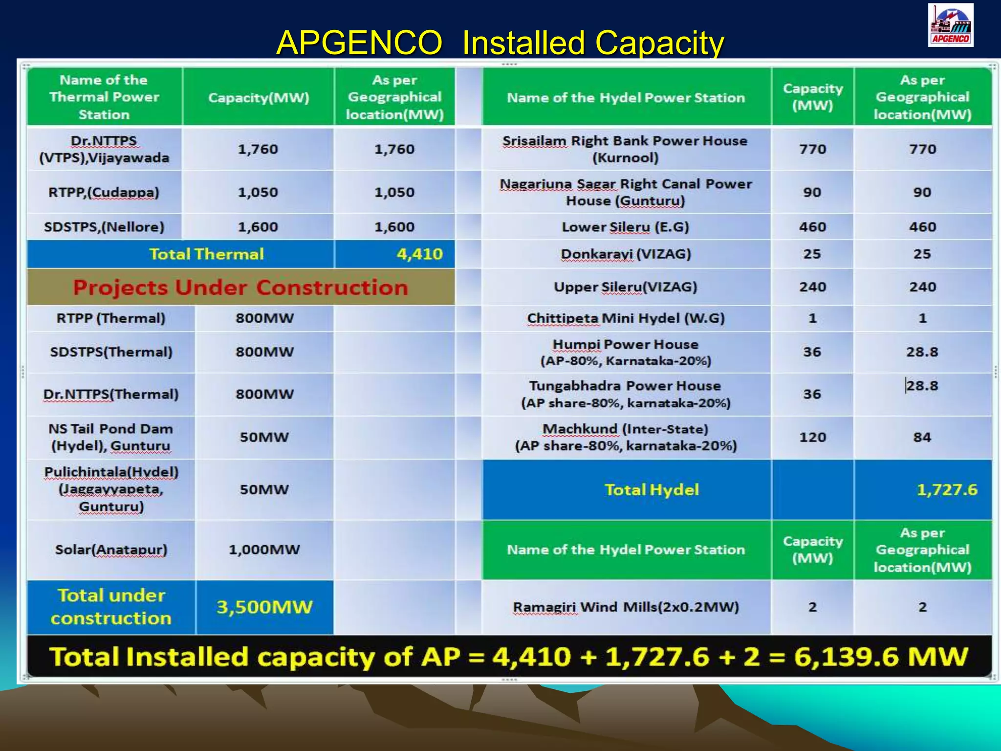
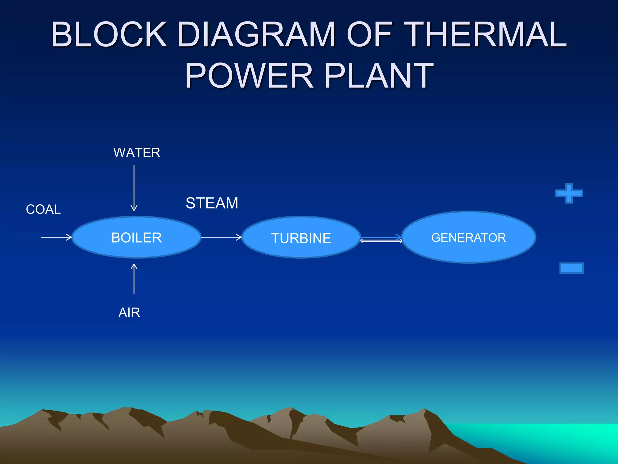
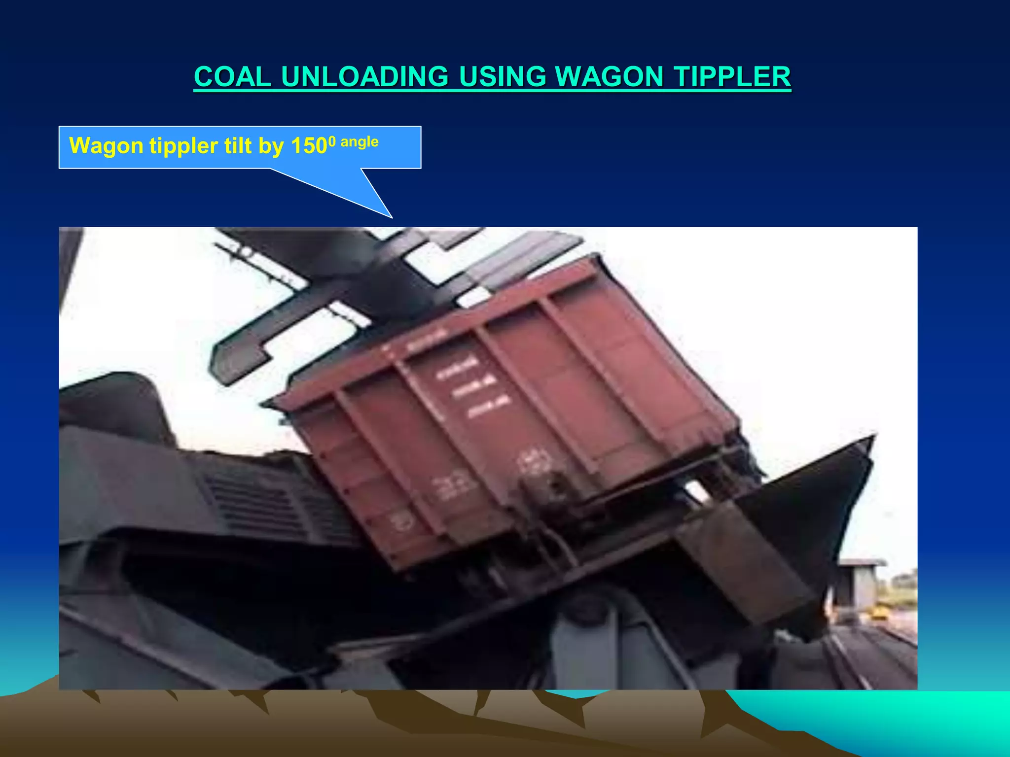
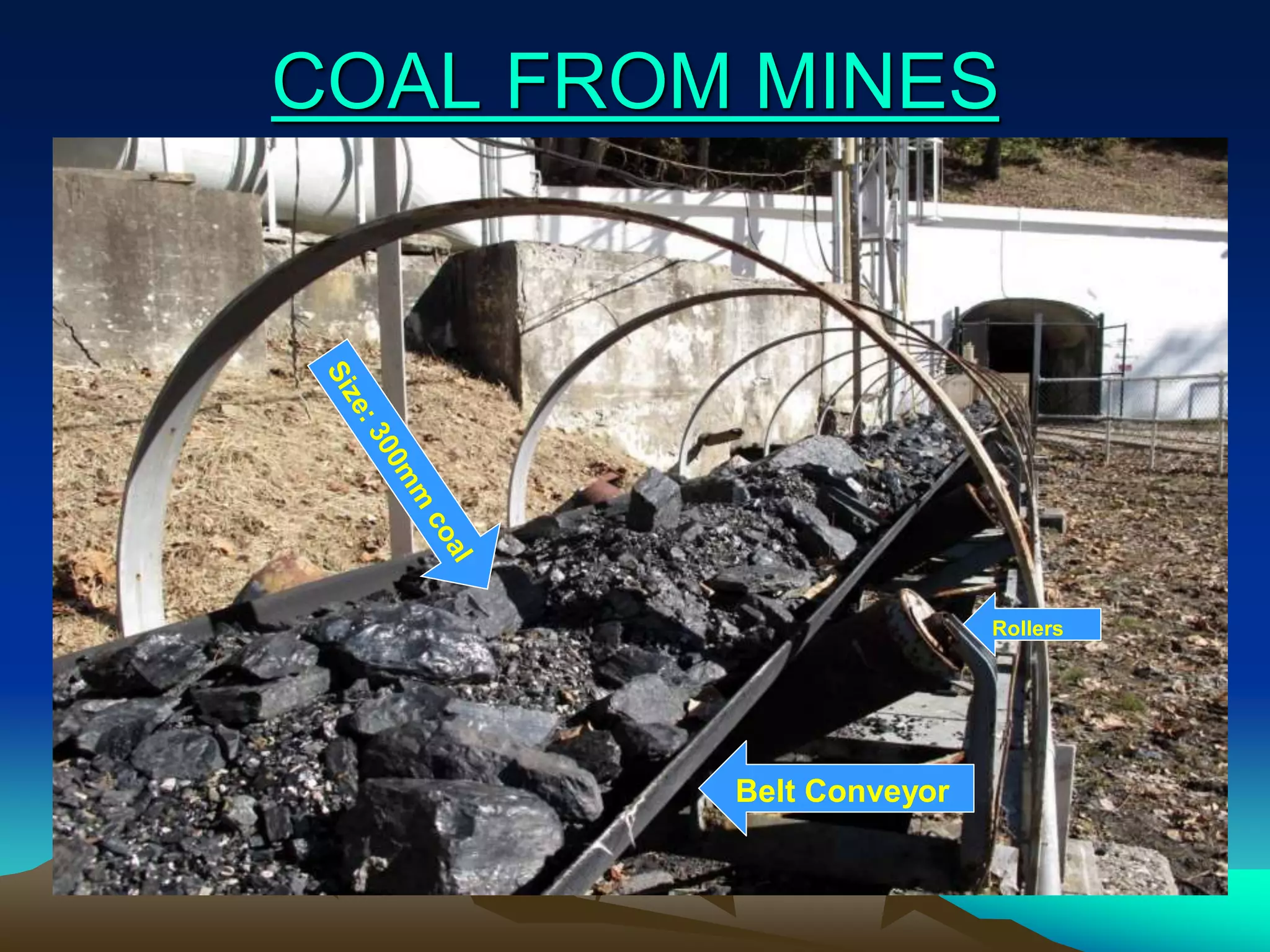
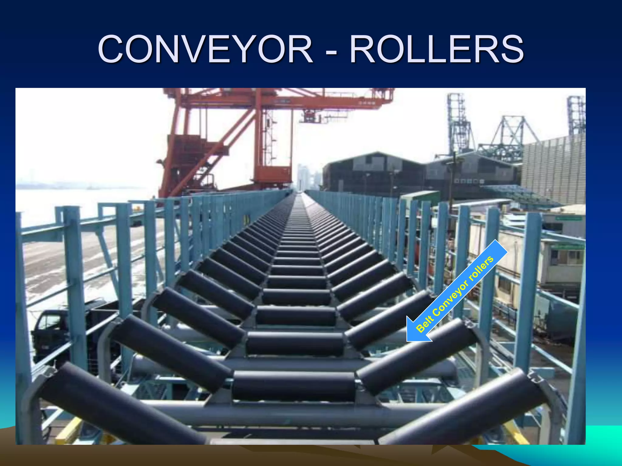
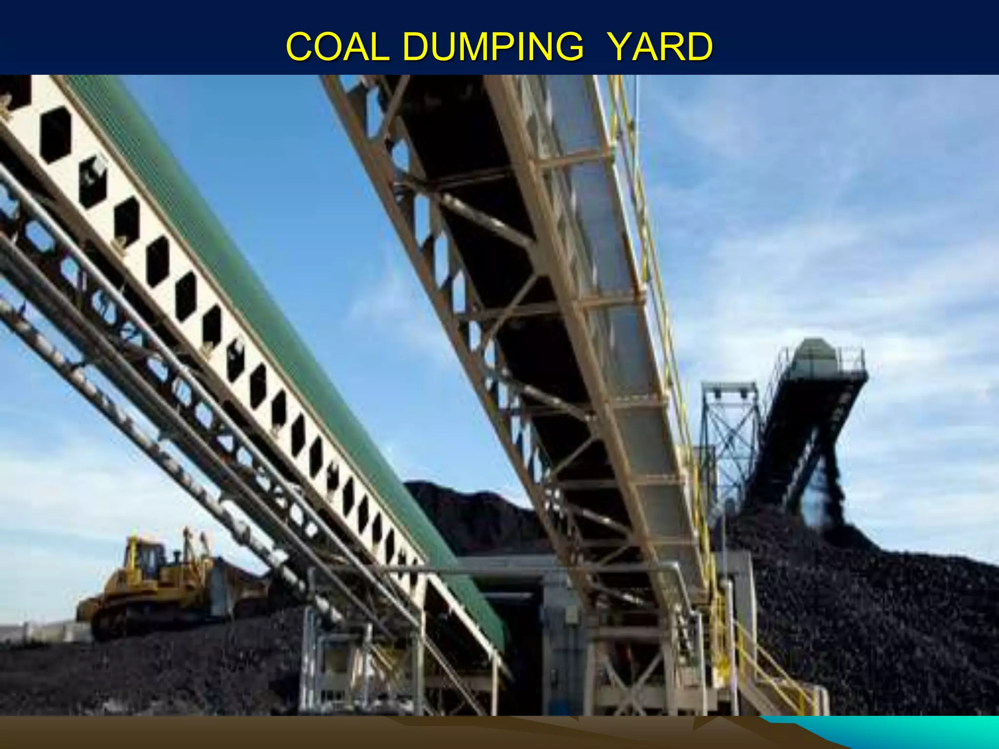
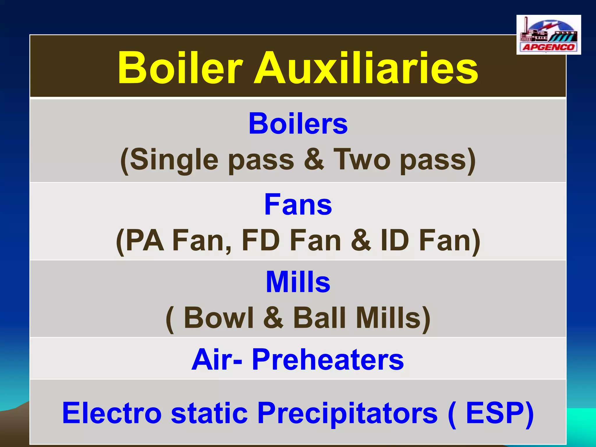
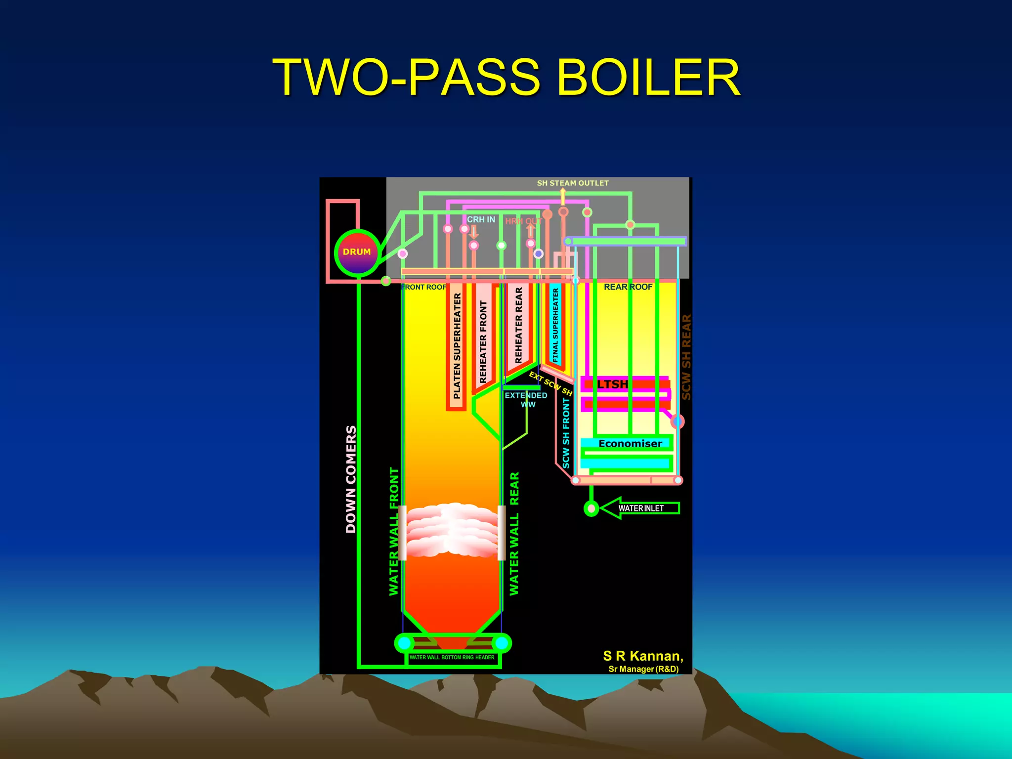
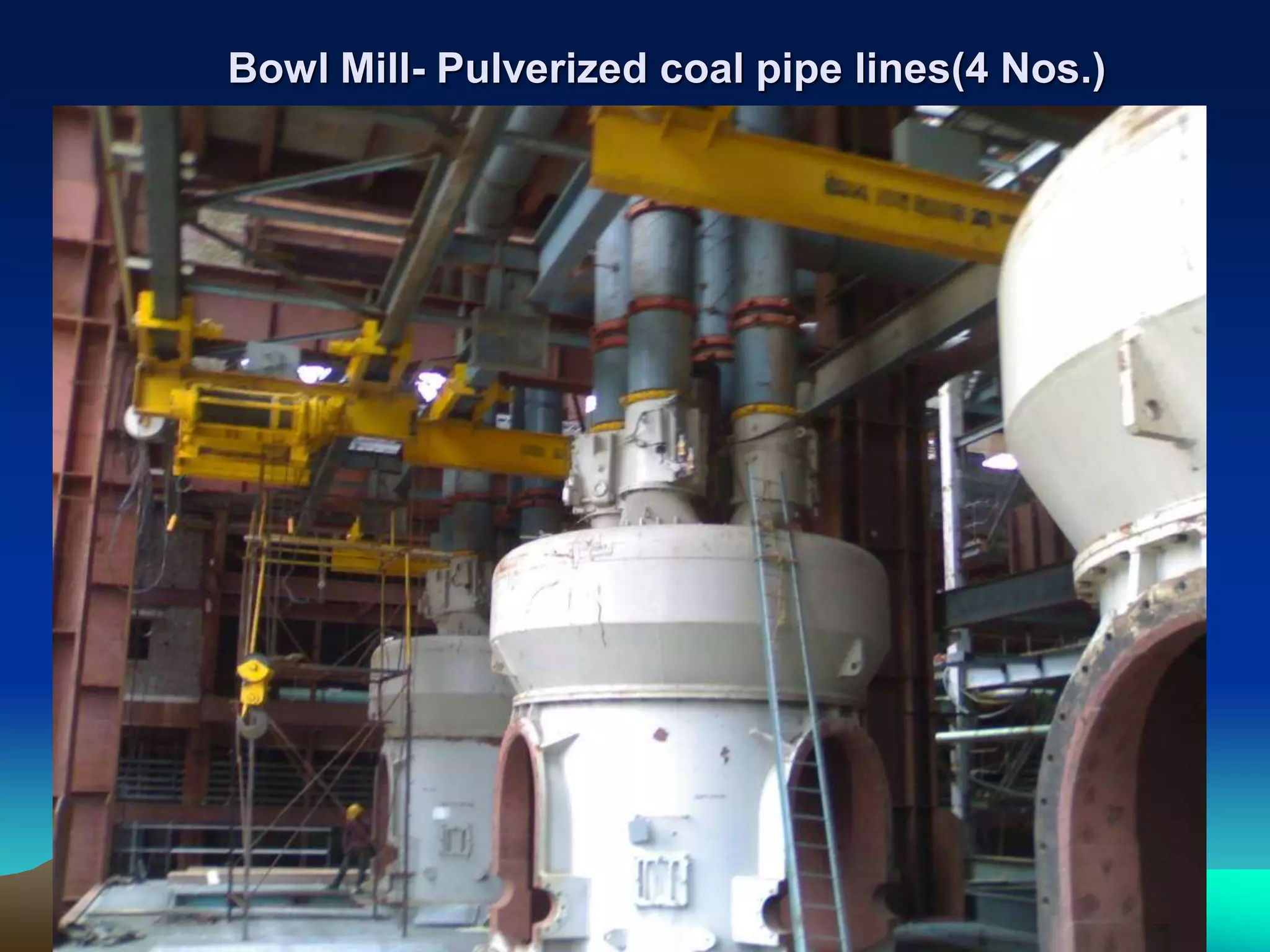
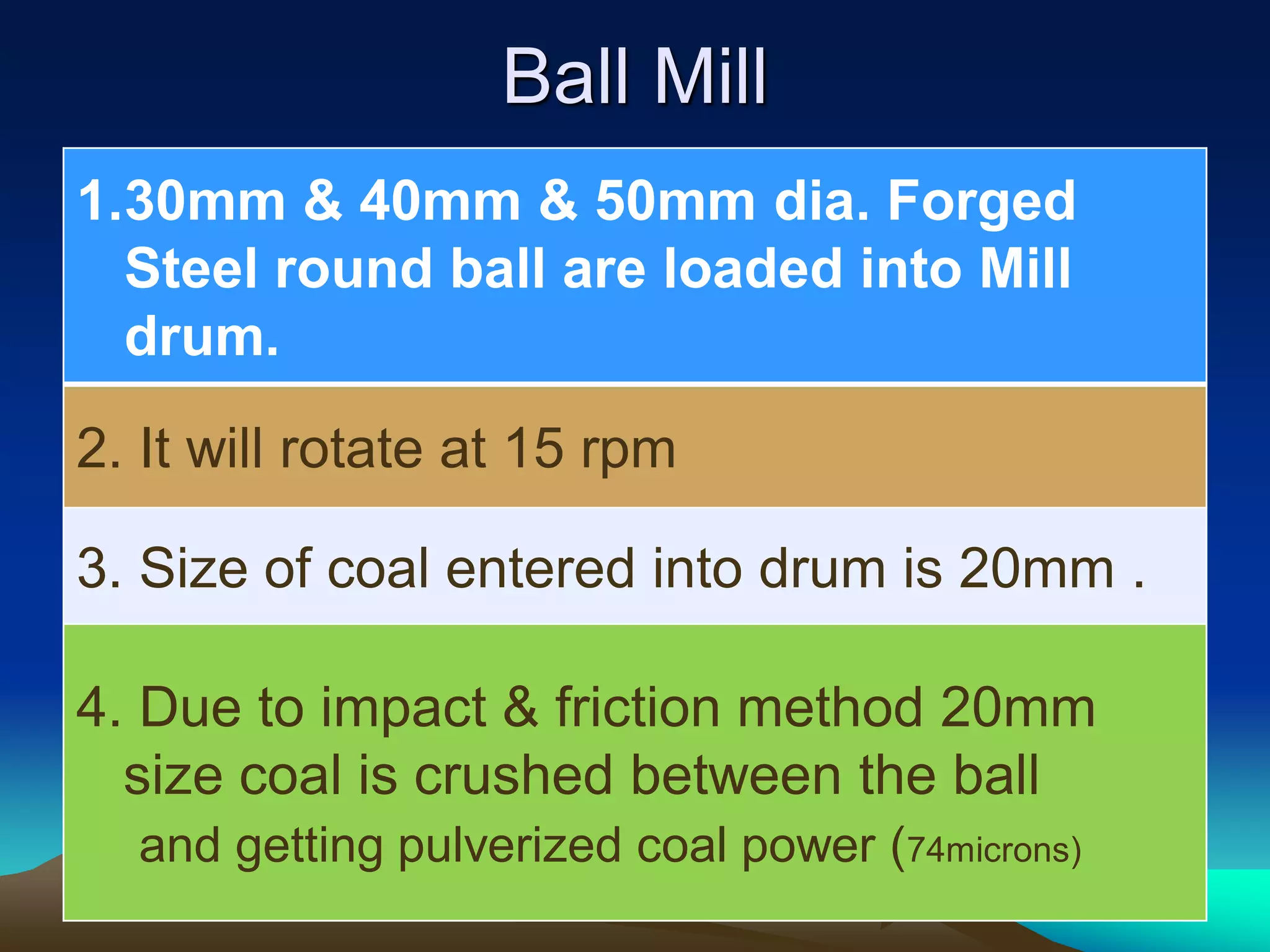
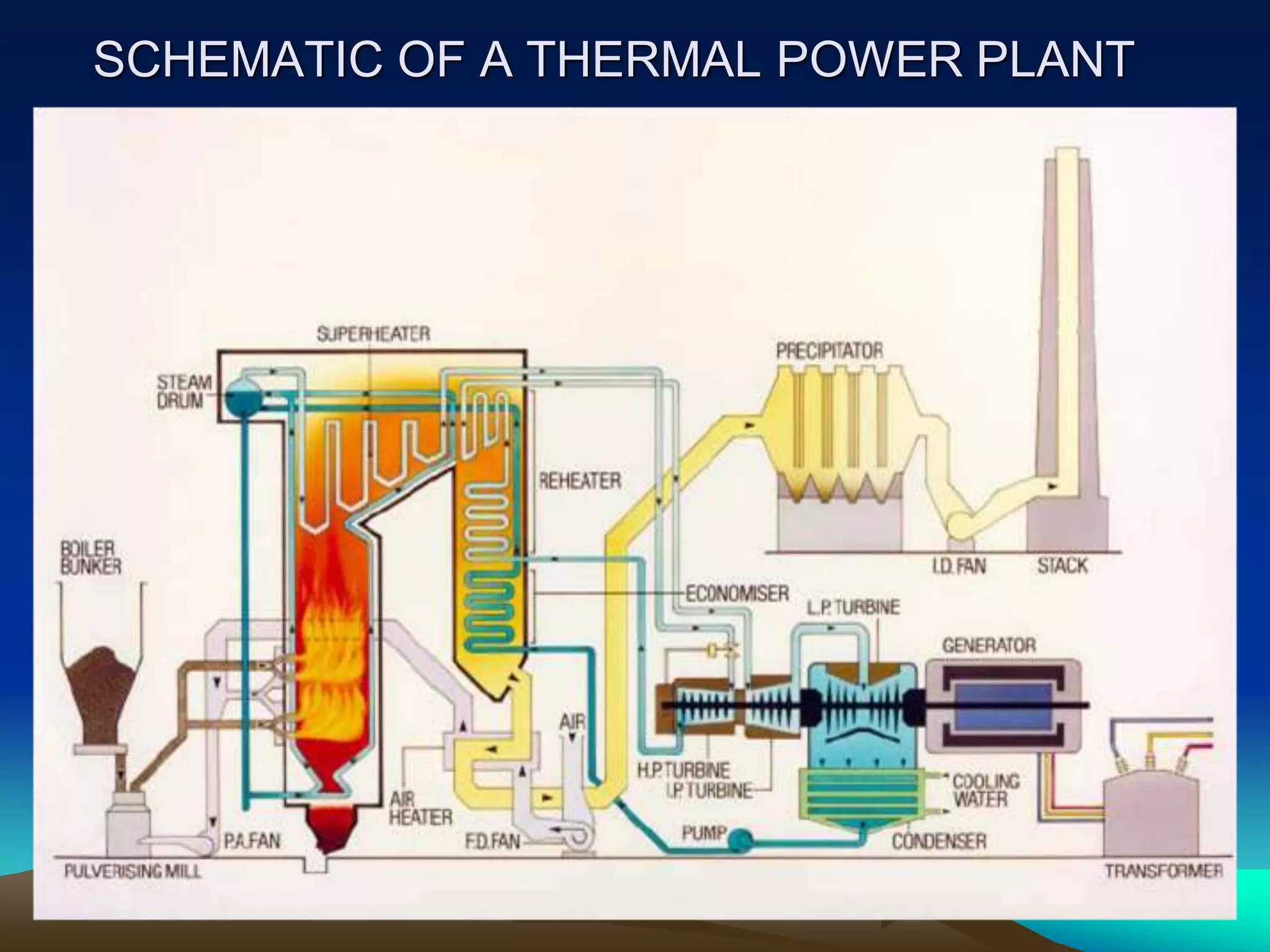
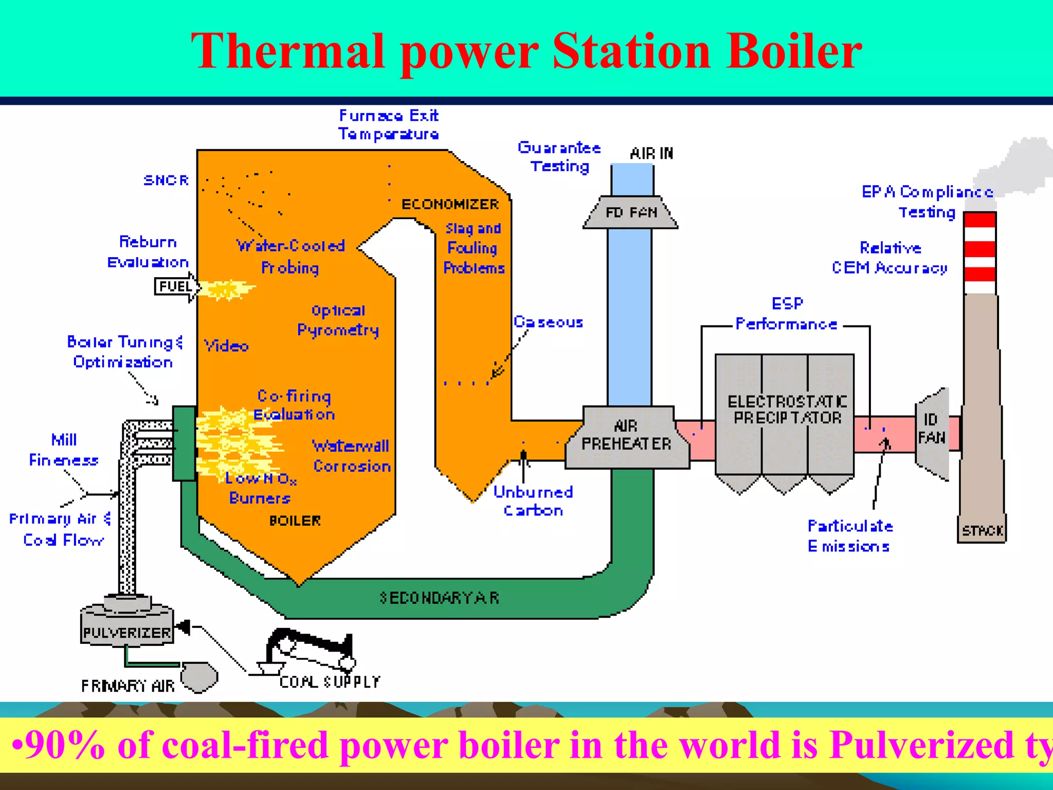
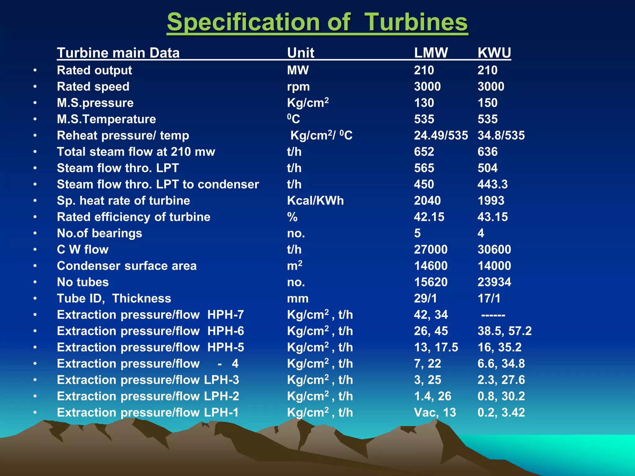
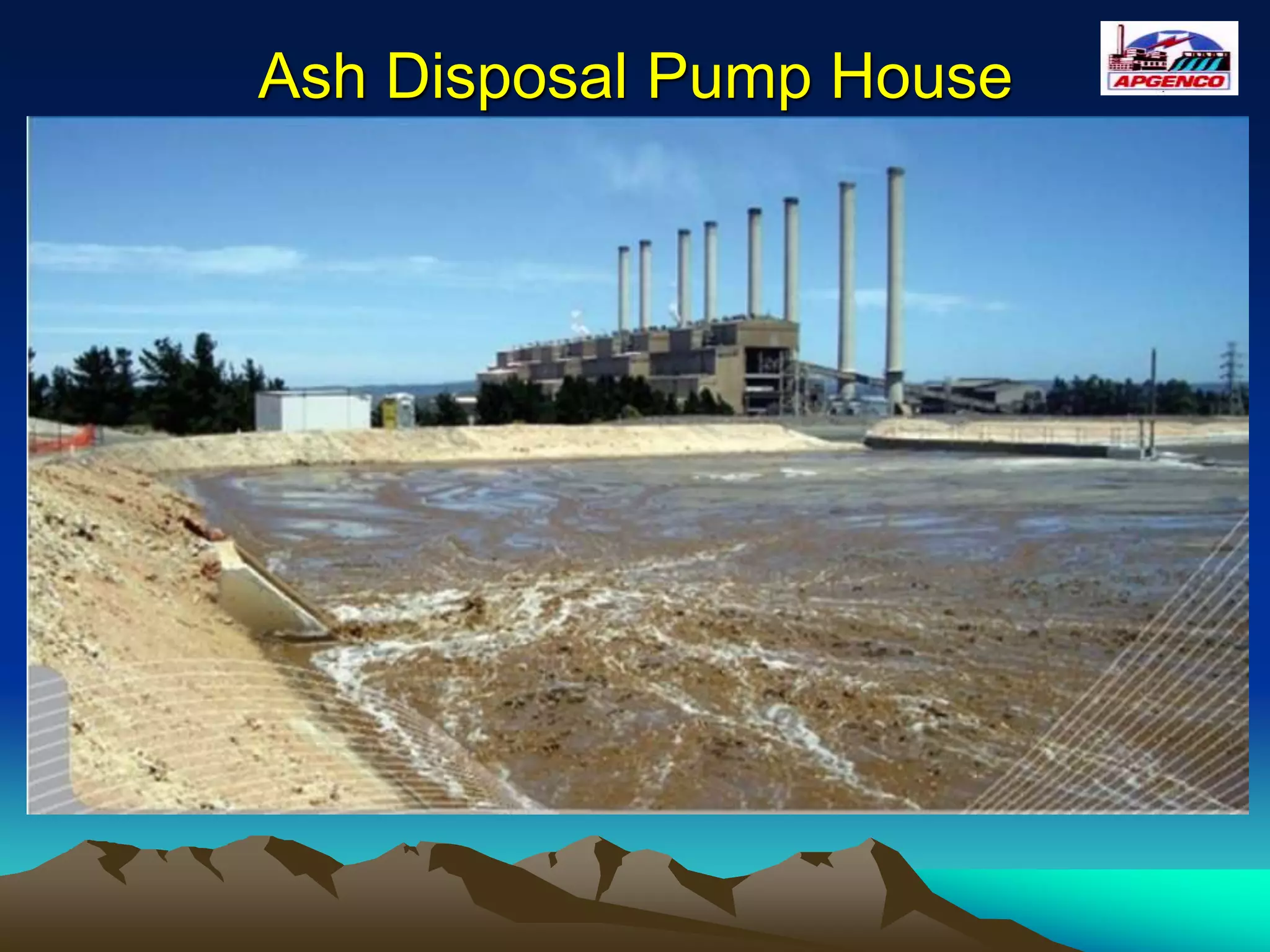
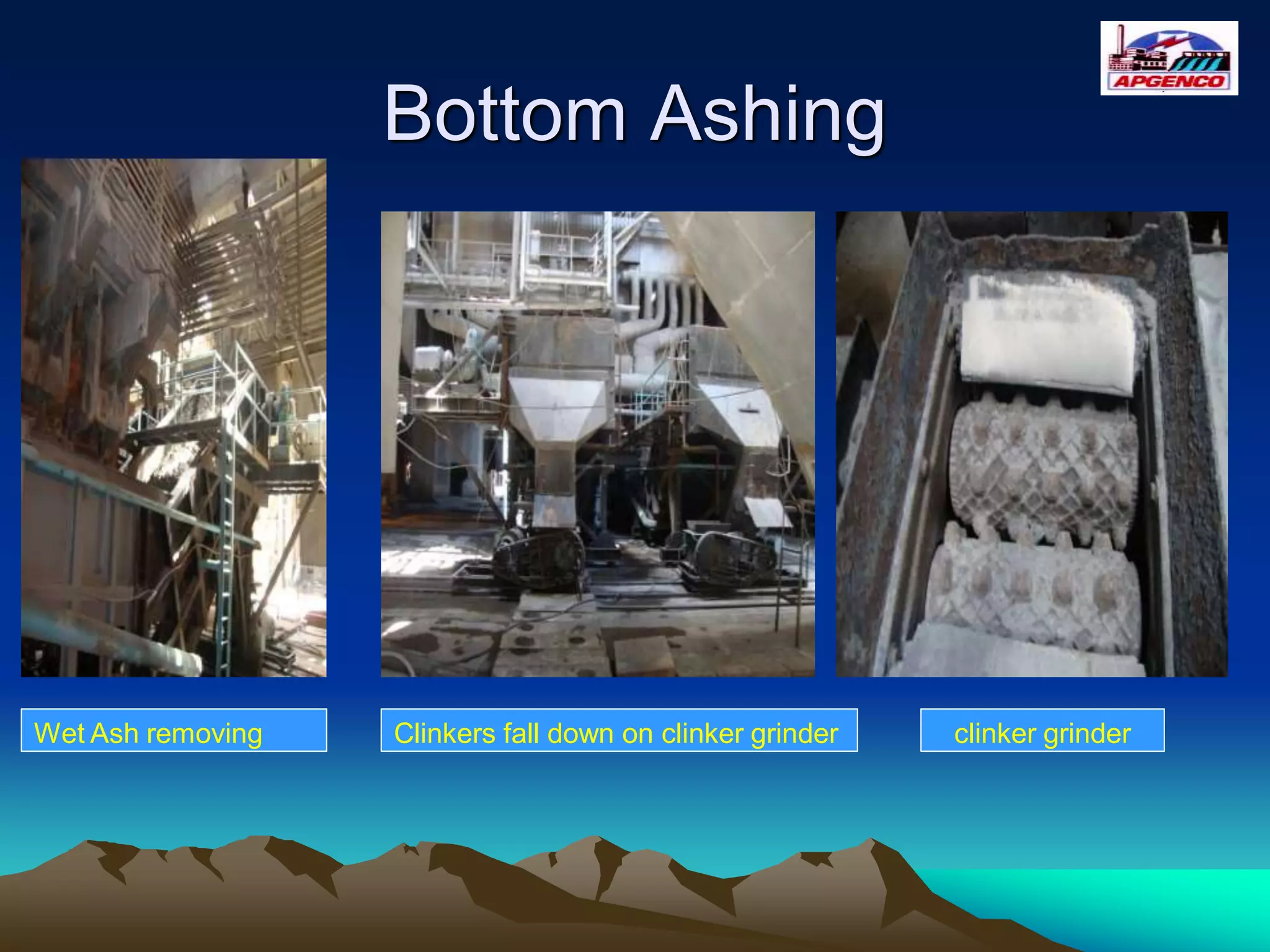
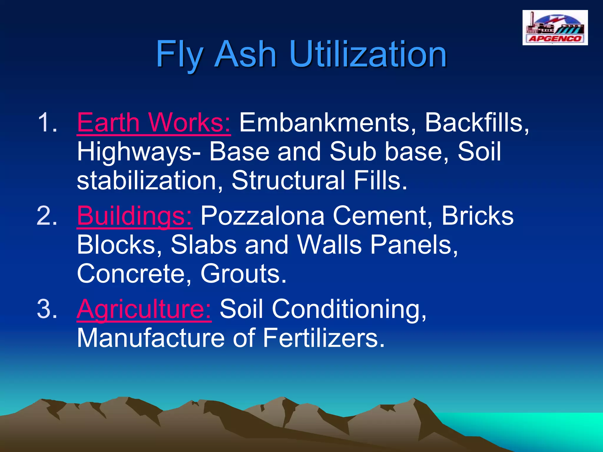
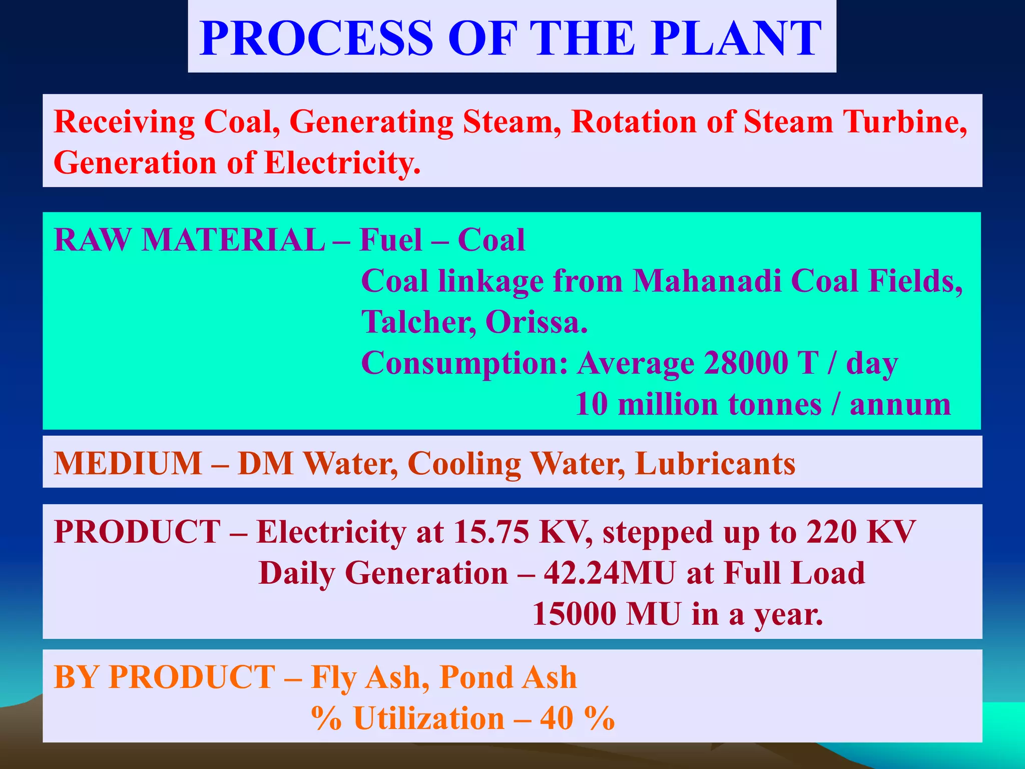
The steam power plant is an important source to produce the electricity. The major portion of electricity demand is fulfilled by this power plant. It is also called a thermal power plant. It provides the electricity required to different areas. In this article we will study the construction, working, efficiency, advantages, and disadvantages of steam power plants It is the power plant which is used to generate electricity by the use of steam turbine. The major components of these power plants are boiler, steam turbine, condenser, and water feed pump.
10. STAGE
NO.
UNIT
NO.
INSTALLED
CAPACITY
DATE OF COMMISSIONING
I 1
2
210 MW
210 MW
01-11-1979
10-10-1980
II 3
4
210 MW
210 MW
05-10-1989
23-08-1990
III 5
6
210 MW
210 MW
31-03-1994
24-02-1995
IV 7 500 MW 29-01-2010
V 8 800 MW
Under construction
Works starts from July-2016
,expected by 2020(4-years)
The project was completed in Four stages, I,II, III & IV
Stages. Consisting of two units of 210 MW each and iv
stage by one unit thus the total capacity being 1760 MW.
11. This session divide in to
Coal handling Plant
Boiler and its Auxiliaries
Turbine and its Auxiliaries
Common Auxiliaries
Generator Auxiliaries
Switch yard
12. BLOCK DIAGRAM OF THERMAL
POWER PLANT
WATER
BOILER TURBINE GENERATOR
COAL
AIR
STEAM
15. Wagon Tippler
Function : The wagon tippler is to tipple or
unload the entire coal in to Conveyor belt
through coal mesh grid.
size of the mesh grid = 300mm X 300mm
24. •Receipt of Coal fro•Unloading of Coal
•Coal Stacking & Reclamation
25. Crusher House:
In this the size of coal
reduced from 300mm to 20mm size coal
pieces with the help of ring rollers.
Bunker:
It is a conical shape container which
receives the 20mm size coal pieces from
crusher house. Its capacity 500MT.
6 Nos. bunkers for each 210 MW unit.
Total coal required for 210MW = 3,000MT per day.
26. Boiler Auxiliaries
Boilers
(Single pass & Two pass)
Fans
(PA Fan, FD Fan & ID Fan)
Mills
( Bowl & Ball Mills)
Air- Preheaters
Electro static Precipitators ( ESP)
27. Types of Boilers
Based on Media
1. Fire Tube Boilers.
2. Water Tube Boilers
Based on Construction
1) Single pass boiler.
2) Two-pass Boiler.
28. SINGLE - PASS BOILER.
(TOWER TYPE BOILER)
From BFP
TO IPT
TOWER TYPE BOILER
DRUM
BOTTOM RING HDR
Economiser
LTRH
LTSH
HTSH
HTRH
ITSH
HANGER PLATEN
TO HPT
AFTER HPT
29. TWO-PASS BOILER
WATER WALL BOTTOM RING HEADER
DRUM
CRH IN
REAR ROOF
WATERINLET
SH STEAM OUTLET
EXTENDED
WW
FRONT ROOF
HRH OUT
S R Kannan,
Sr Manager (R&D)
LTSH
Economiser
30. HOW TO RECONGNISE GOOD COMBUSTION?
COLOUR OF FLAME AT BURNER ELEVATION
OBSERVED THROUGH PEEP HOLES
COLOUR- PALE ORANGE WHILE ON COOL FIRING
FLAME 300 TO 400 mm AWAY FROM BURNER TIP.
FLAME TEMP. 1050 Deg.C TO 1150 Deg.C
(AS MEASURED BY OPTICAL PYROMETER)
31. Water Tube Boiler (Box Type )
Boiler Drum
Water wall tube
Peep Hole
Coal feeding
Furnace Area
Super Heater Coils
Bottom Ring
Header
Top Ring Header
35. PA Fan Function:
The air supplied by the fan is called
primary Air. The primary air is used to lift the
pulverized coal in the mill to Furnace for combustion.
FD Fan function:
The air supplied by the FD fan is called
Secondary Air. The Secondary air is used to combustion
the pulverized coal effectively in the furnace zone .
ID Fan function:
It removes / suck the flue gasses from the
furnace and exit the flue gasses to the atmosphere through
the chimney .
40. BALL TUBE MILLS
• These mills are manufactured as per
STEIN, France design.
• Type : BBD 4760
• BBD stands for Boyer’s Balls Direct.
• 4760 stands for 4.7 meters inside diameter
and 6.0 meter length of the Pulverizing
zone.
• These are also called horizontal mills as
their axis of rotation is horizontal .
41. Ball Mill
1.30mm & 40mm & 50mm dia. Forged
Steel round ball are loaded into Mill
drum.
2. It will rotate at 15 rpm
3. Size of coal entered into drum is 20mm .
4. Due to impact & friction method 20mm
size coal is crushed between the ball
and getting pulverized coal power (74microns)
42. SREW CONVEYOR
The purpose of SREW CONVEYOR is to convey raw coal and balls
into the mill and to convey Primary air through the center of the
conveyor
45. Pulverized Fuel Boiler
Tangential firing
Coal is pulverised to a fine powder, so that less than 2% is +300
microns, and 70-75% is below 75 microns.
Coal is blown with part of the combustion air into the boiler plant
through a series of burner nozzles.
• Combustion takes place at
temperatures from 1300-1700°C
• Particle residence time in the
boiler is typically 2-5 seconds
• One of the most popular system
for firing pulverized coal is the
tangential firing using four
burners corner to corner to create a
fire ball at the center of the
furnace. See Figure
52. AIR PREHEATER
Air pre heater is an auxiliary equipment for
steam generators. It is a heat exchanger that
absorbs waste heat from exit flue gas in boiler
and transfers the heat to the cold air.
In utility and process boilers it is used to
heat the air required for efficient combustion
purpose, to drying the coal.
65. SUPER HEATER
FUNCTION:
It increases the temperature of Main
steam with the help of temperature
of flue gases to get Saturated Steam
admitted to the HPT.
66. RE - HEATERS
FUNCTION:
It heats the temperature of steam
outlet from HPT with the help of Flue
gas temperature.
74. BOILER DRUM
FUNCTION:
• It separates the steam from steam-water mixture.
• It houses all equipments used for purification of
steam, after being separated from water.
90. TYPE OF TURBINES
STAGE – I
Three cylinder, Tandem Compound, Impulse, Reheat and
Condensing type with double flow in LP Turbine & Nozzle
Governing
STAGE – II & III
Three cylinder, Tandem Compound, Reaction, Reheat and
Condensing type with double flow in IP Turbine & LP
Turbine and Throttle Governing
STAGE – I V
Three cylinder, Tandem Compound, Impulse, Reheat and
Condensing type with double flow in LP Turbine & Nozzle
Governing with TDBFP
101. Ash collection points
Generally ash will be collected by the following locations.
1) Ash collected at Bottom Ashing. ( Moderately)
2) Ash collected at ESP Hoppers.( Major portion)
3) Ash collected at Duct Hoppers.
4) Ash collected at APH Hoppers.
5) Ash collected at Economizer Hoppers.
6) Ash collected at Scraper conveyors.
7) Stack hoppers
8) Common ash slurry sluice way trench)Ash pump house
10) Ash disposal lines
11) Ash pond
111. Fly Ash Utilization
1. Earth Works: Embankments, Backfills,
Highways- Base and Sub base, Soil
stabilization, Structural Fills.
2. Buildings: Pozzalona Cement, Bricks
Blocks, Slabs and Walls Panels,
Concrete, Grouts.
3. Agriculture: Soil Conditioning,
Manufacture of Fertilizers.
112. TotalHeatinput100%
Heat Loss in Flue gas ~5%
Losses in boiler and piping ~8%
Losses in Turbine, Generator and
Transformer ~4%
Condenser cooling water rejection ~45%
Unit self consumption ~3%
NetavailableEnergy~35%
Energy Distribution
113.
114. TYPE OF GENERATORS
STAGE – I
Alternator with Cylindrical rotor, Static excitation,
3-Phase Double Star Winding, Water & Hydrogen
cooled
STAGE – II , III & IV
Alternator with Cylindrical rotor, Brush less excitation,
3-Phase Double Star Winding, Hydrogen cooled
116. TURBO GENERATOR
• The main parts of a Turbo Generator are
STATOR and ROTOR.
• Detailed constructional features
• STATOR BODY:
Stator body is a robust totally enclosed
gas tight fabricated structure.
Designed mechanically to withstand high
internal pressure of explosion of Hydrogen
–Air mixture
Hydrogen gas coolers are housed
longitudinally inside the stator body
The end shields are made in 2 halves for
ease in assembly
117. TURBO GENERATOR
• STATOR CORE:
Made up of segmental, varnished insulated
punchings of CRGO silicon steel laminations
Built in several packets separated by steel
spacers for radial cooling of the core by
Hydrogen
Pressing of the core stampings is done to
ensure monolithic core
Core is held firmly by means of Heavy Non –
Magnetic Steel press rings bolted thoroughly
with the ends of core bars
119. TURBO GENERATOR
STATOR WINDING:
Three phase, double layer short chorded bar type
windings with two parallel paths
Each coil consists of glass insulated solid and hollow
conductors
The elementary conductors are transposed in the slot
portion to minimize eddy losses.
Coils are held in the slots firmly in the slots by fibrous
wedges.
Overhang portion is securely tied with glass cord to
binding rings and special Non-Magnetic brackets
121. TURBO GENERATOR
• Distillate Headers:
Two Copper ring type water headers are
provided for both inlet and outlet of the Stator
winding on the Turbine end
The winding ends are solidly soldered into the
coil lugs which pass ultrasonic test
Each individual bar is connected with PTFE
hose which in-turn are connected to ring header
The water circuit is subjected to Hydraulic test at
various stages to ensure water tight
122. TURBO GENERATOR
• TERMINAL BUSHINGS
Porcelain insulators are provided to insulate the
terminal bars from the stator body
Terminal bushings are situated in the lower part
of the stator casing (Slip ring side)
Sealing is provided between bushings and stator
body to avoid any possibility of leakage of
Hydrogen gas
Three phase and six Neutral bushings are
available.
123. TURBO GENERATOR
• ROTOR
The rotor shaft is a forged from one single piece
from Chromium, Nickel, Molybdenum and
Vanadium steel.
It undergoes all types of series of mechanical
tests to ensure any internal flaws.
Rotor is dynamically balanced to a high degree
of accuracy.
125. TURBO GENERATOR
Field winding:
Field winding is made up of hard drawn silver bearing
copper.
It is held in position against centrifugal forces by means
of duralumin wedges in the slot portion
Overhang portion is held by the non-magnetic steel
retaining ring.
Several ventilating ducts are milled on the slots for
Hydrogen gas cooling of the rotor.
Copper segmental type damper winding is provided to
prevent overheating of retaining rings
126. TURBO GENERATOR
Shaft Mounted Fans
For circulating the Hydrogen gas inside the
Turbo Generator two propeller type fans are
mounted on either sides of the rotor shaft
Alloy steel cast fan blades are machined in the
tail portion with special profile
Fan shields are fixed to the end shields to guide
the flow of Hydrogen gas
127. TURBO GENERATOR
RETAINING RINGS
End windings are held intact against centrifugal forces by
retaining rings machined from stress free, heat treated
non-magnetic alloy steel.
Retaining rings are shrunk fitted on the rotor body.
Centering rings mounted at the end of retaining rings
support and prevent the movement of rotor winding in
axial direction.
128. CROSS SECTIONAL VIEW OF TURBO GENERATOR
Stator Winding
ROTOR
RET RING
Seal Rings
Bushings
Gas cooler
129. TURBO GENERATOR
SLIP RINGS
Helically grooved alloy steel rings are shrunk on the
rotor.
Both the rings are mounted on a common single steel
bush which has an insulating jacket.
Radial holes are made on the slip rings for fixing Current
Carrying Bolts.
Slip rings are connected to the field winding thru semi
flexible copper leads.
130. TURBO GENERATOR
BRUSH GEAR
Brush gear is provided on the extended part of
the bearing pedestal on the excitation side.
Brush holders are fixed on the brass rings in
such a way to provide staggering of the brushes
along the circumference of the ring.
Brushes are loaded with contact pressure which
can be adjusted individually.
Brushes can be replaced easily during normal
running condition.
131. TURBO GENERATOR
GAS COOLERS
Four numbers gas coolers are mounted longitudinally
inside the TG stator body.
Gas coolers consist of cooling tubes made out of brass
and coiled copper wire is wound to increase the surface
area of cooling.
Cooling water flows thru the tubes (inside) and hot
Hydrogen across the cooler surface thereby taking away
the heat from the gas.
132. TURBO GENERATOR
SHAFT SEALS
Shaft seals are provided in order to prevent Hydrogen
escape from the TG casing along the rotor shaft.
Seal oil (pressurized) is a used to seal Hydrogen gas
escape.
The shaft seals are radial thrust type and are mounted
between end shield and the bearing at either ends of the
Rotor.
133.
134. HISTORY OF GENERATORS
Electro-Magnetic Induction principle enunciated by Sir Micheal Farady 1831.
First AC Turbo –Generator was developed by Sir Charles A Parsons 1888.
First 3 phase generator, salient pole 1900.
First turbo type 3 phase 25 MW generator 1912.
CEA, UK made 50 HZ as standard frequency for Europe 1925.
First Hydrogen cooled 3 phase 30 MW generator 1937.
First Hydrogen cooled TG with direct cooling of rotor 1949.
First generator with water cooled stator winding 1956.
First generator with water cooling for stator and rotor winding 1959.
158. TRIP LOGIC OF GENERATOR PROTECTION
• TWO INDEPENDENT CHANNELS WITH INDEPENDENT CT/VT
INPUTS/DC SUPPLY/TRIP RELAY
CLASS - A TRIPS
• ALL ELECTRICAL TRIP
• TRIP TURBINE , GENERATOR,GT,UT
CLASS - B TRIPS
• MECHANICAL TRIPS
• AVOID OVER SPEEDING OF TURBINE DUE TO STEAM ENTRAPPED
IN TURBINE. TURBINE TRIP SIGNAL IS GIVEN FIRST AND THE ACTIVE
POWER, SENSED BY THE LOW FORWARD RELAY (32G) GIVES THE
TRIP SIGNAL TO THE UNIT BREAKER & FIELD BREAKER AFTER A
TIME DELAY
CLASS - C TRIPS
• TRIPS ONLY HV CB IN CASE OF GCB SCHEME
164. PROCESS OF THE PLANT
Receiving Coal, Generating Steam, Rotation of Steam Turbine,
Generation of Electricity.
RAW MATERIAL – Fuel – Coal
Coal linkage from Mahanadi Coal Fields,
Talcher, Orissa.
Consumption: Average 28000 T / day
10 million tonnes / annum
MEDIUM – DM Water, Cooling Water, Lubricants
PRODUCT – Electricity at 15.75 KV, stepped up to 220 KV
Daily Generation – 42.24MU at Full Load
15000 MU in a year.
BY PRODUCT – Fly Ash, Pond Ash
% Utilization – 40 %