Downloaded 1,112 times
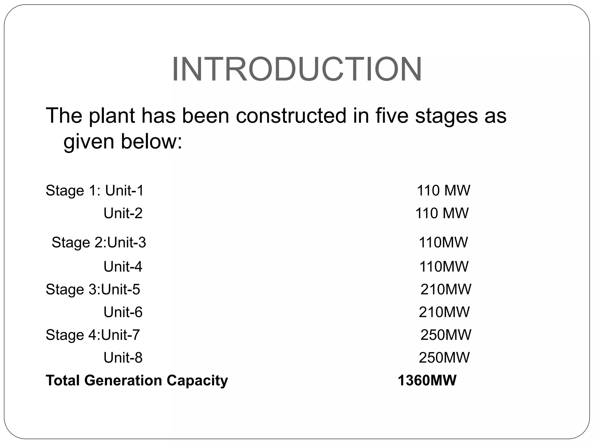

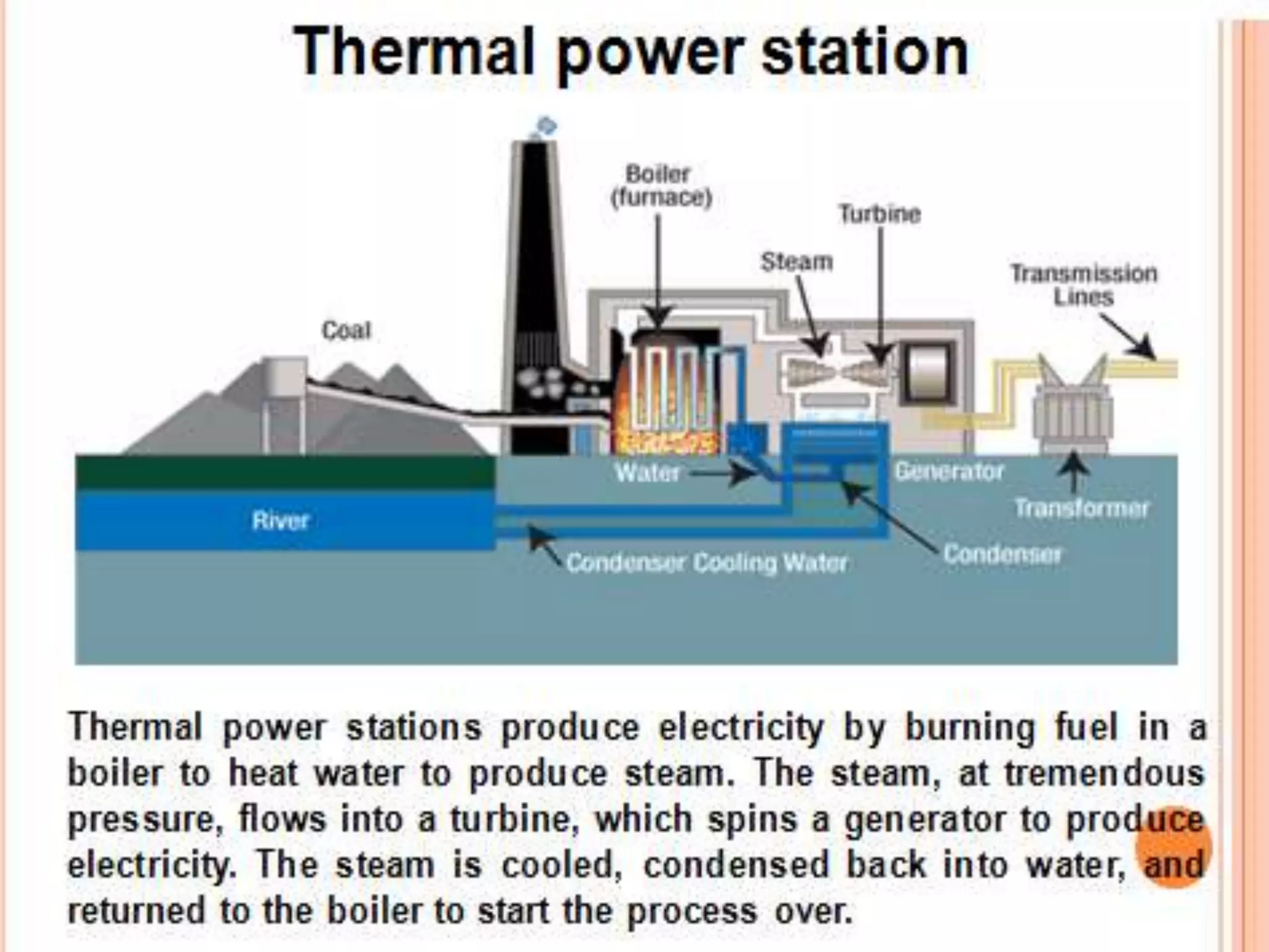
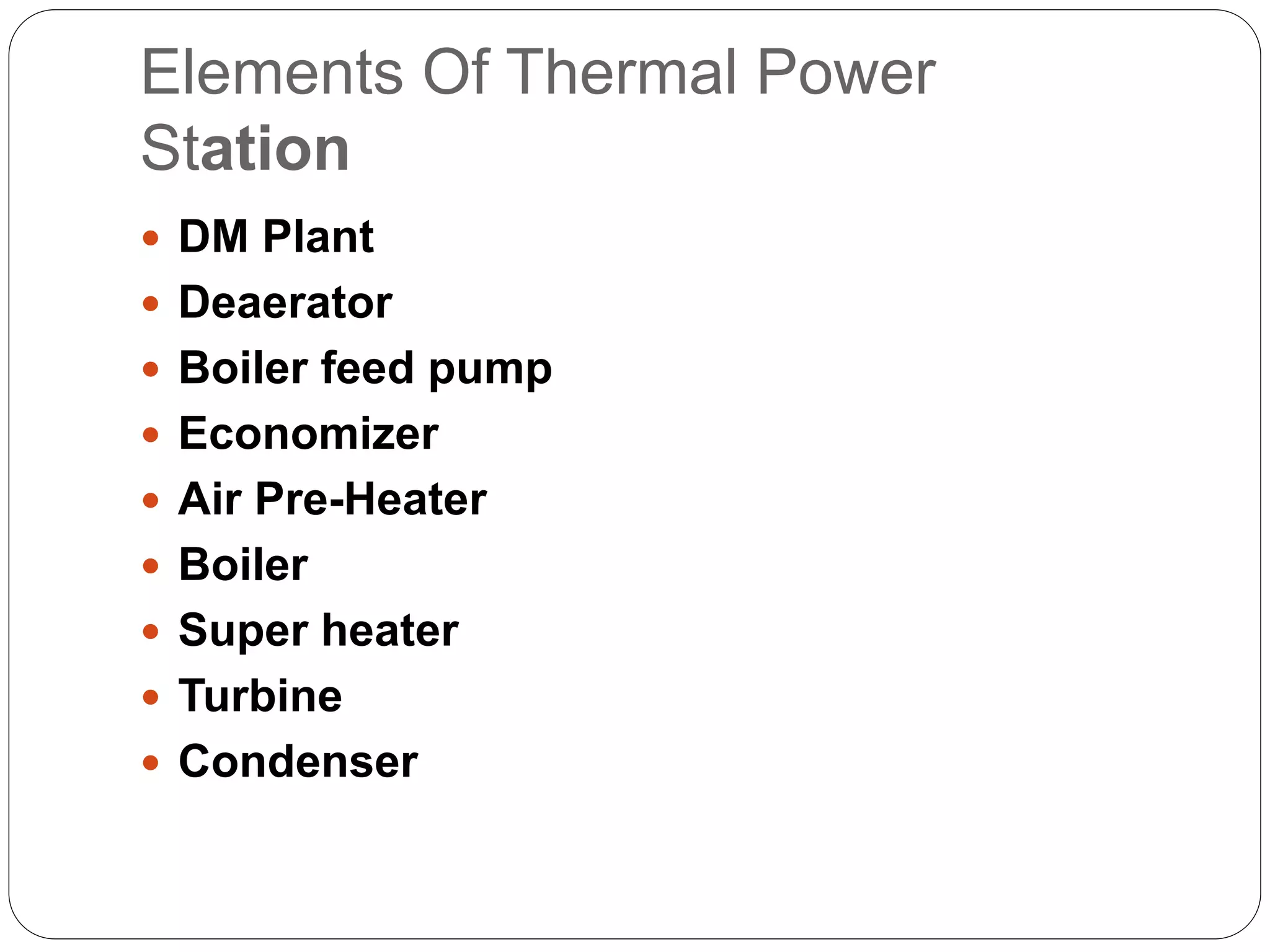
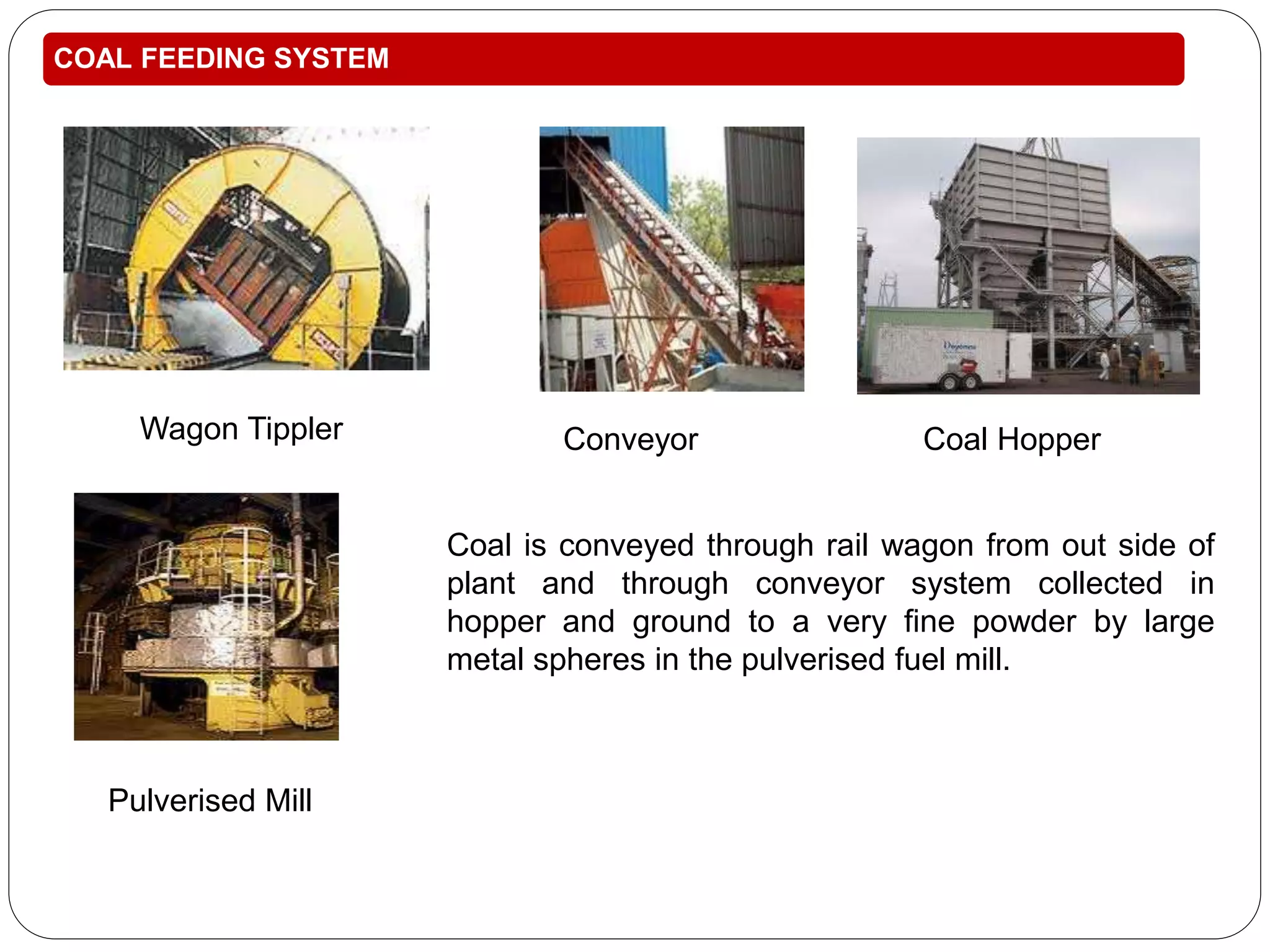

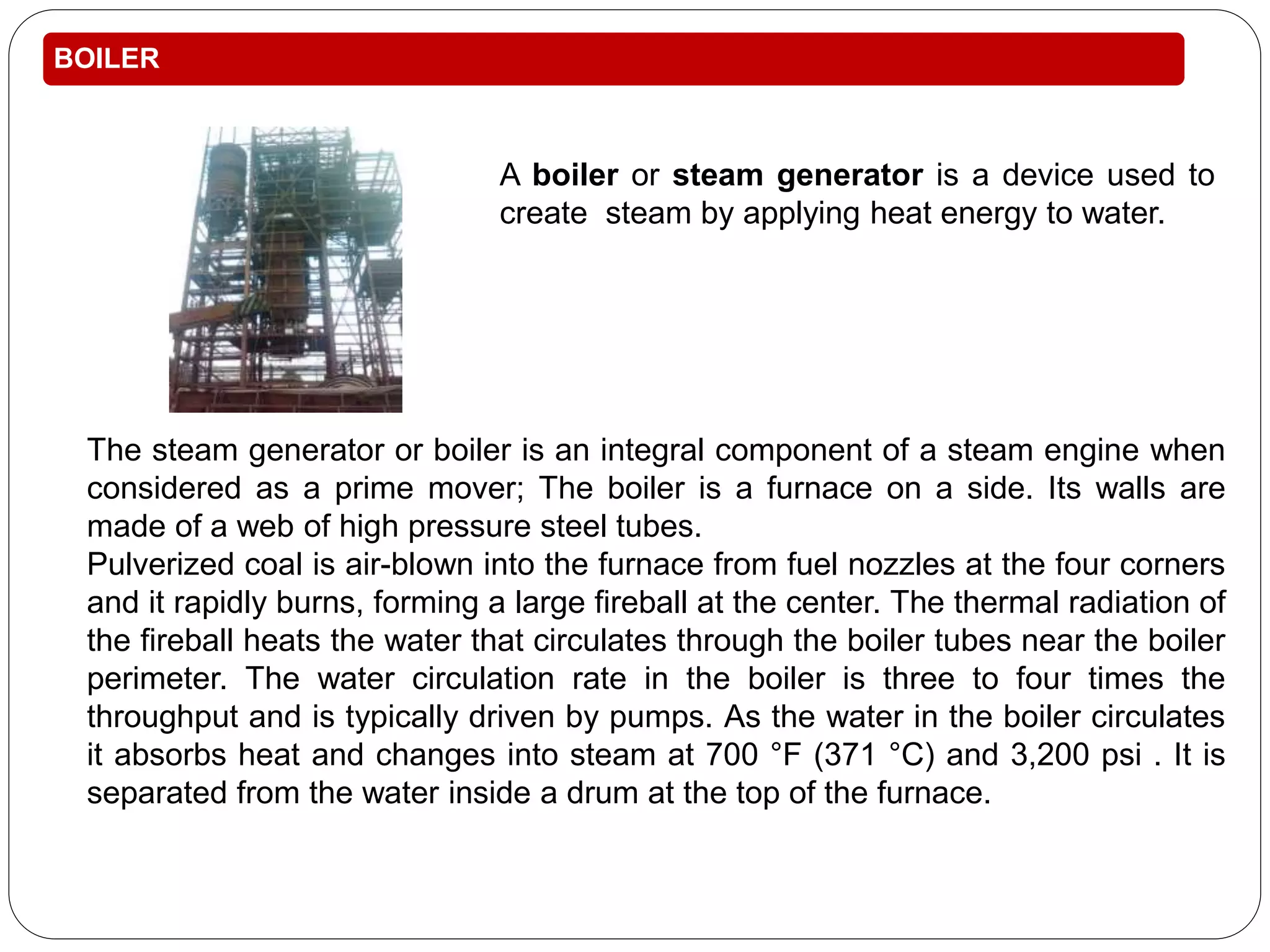


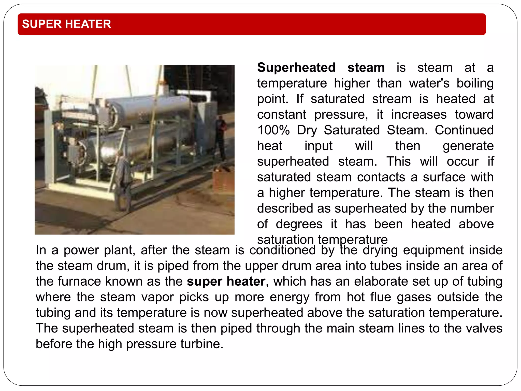
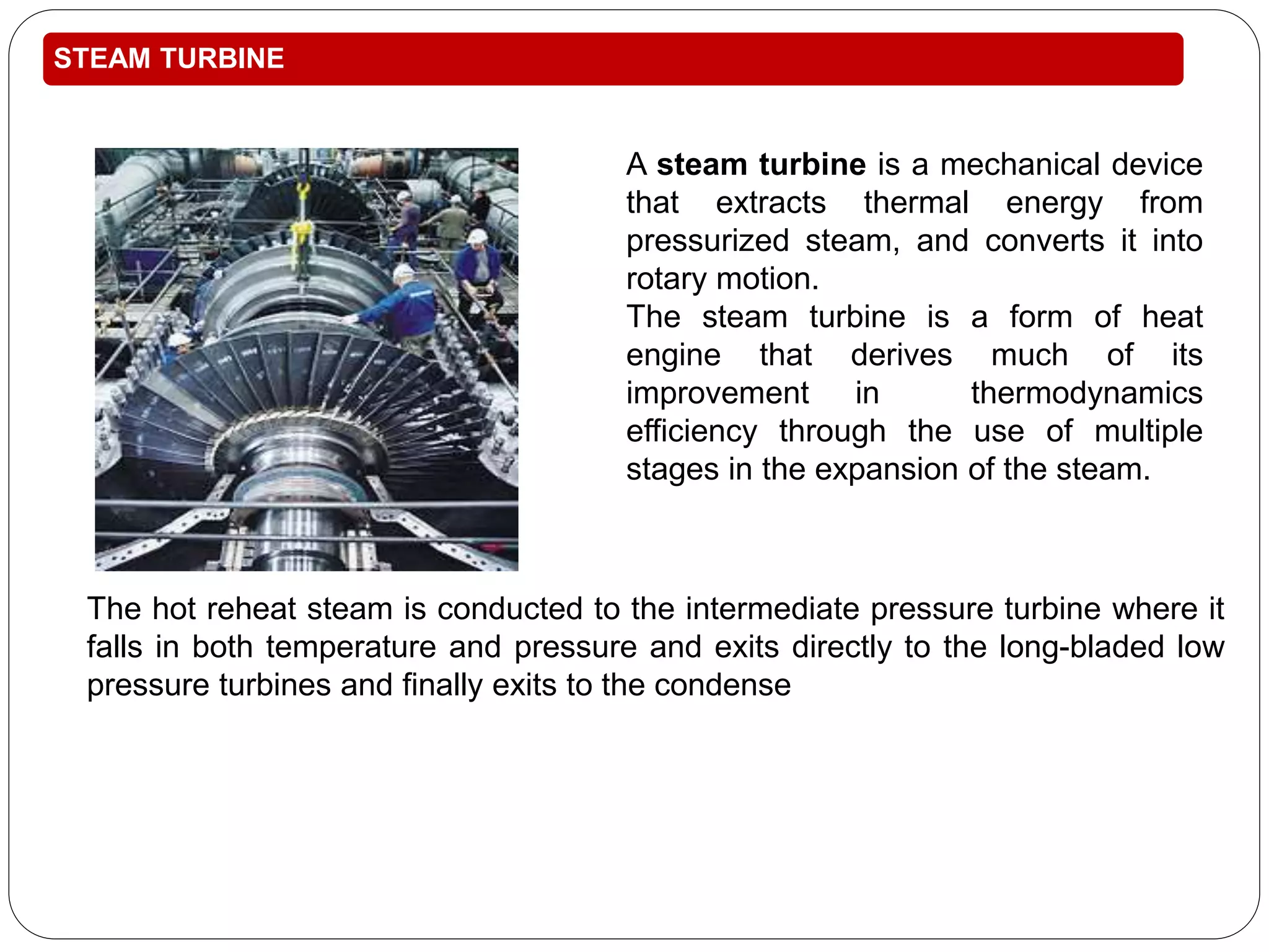
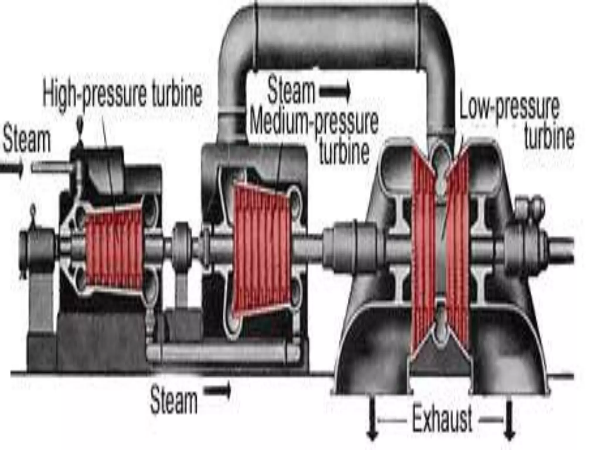

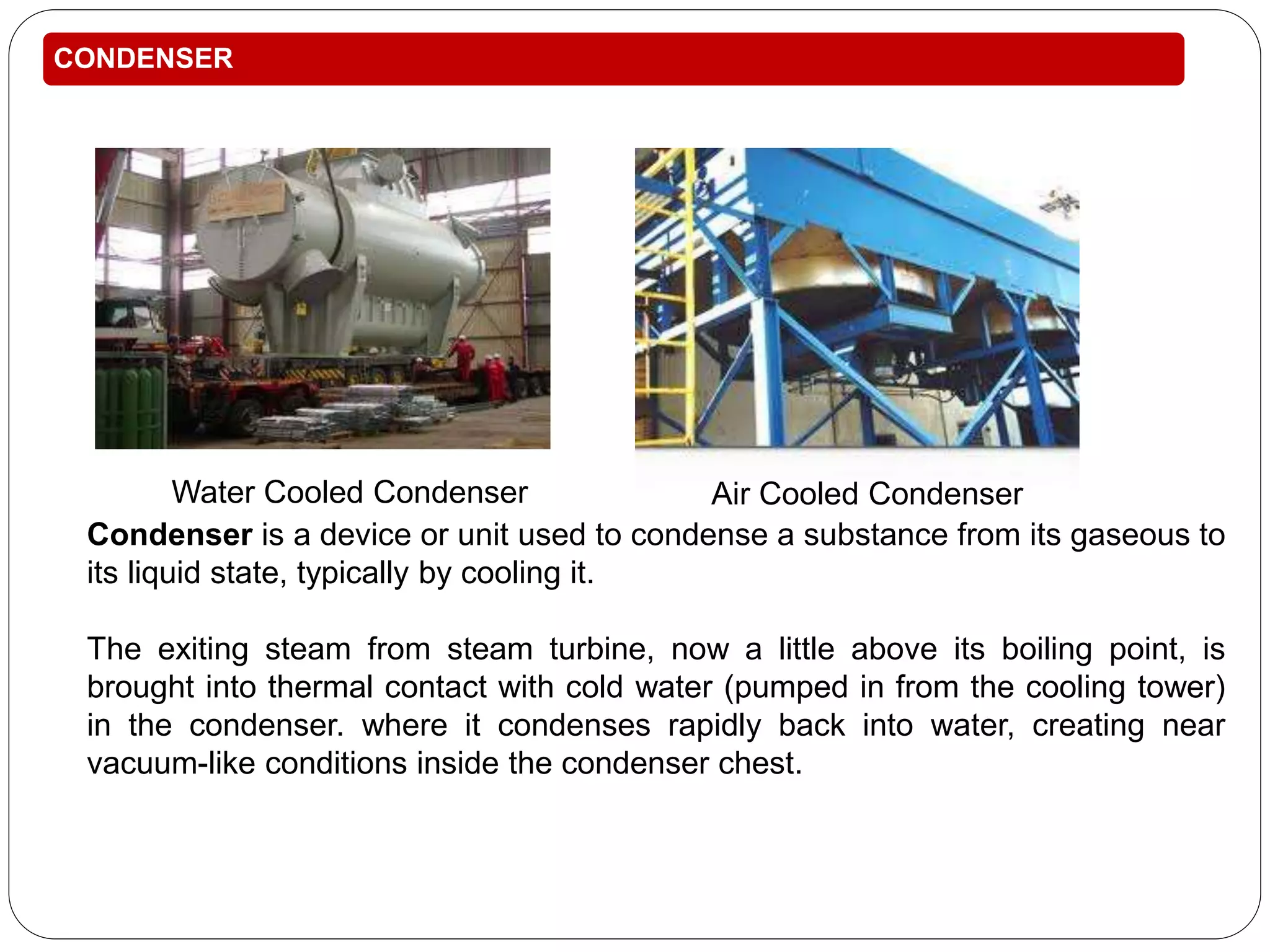


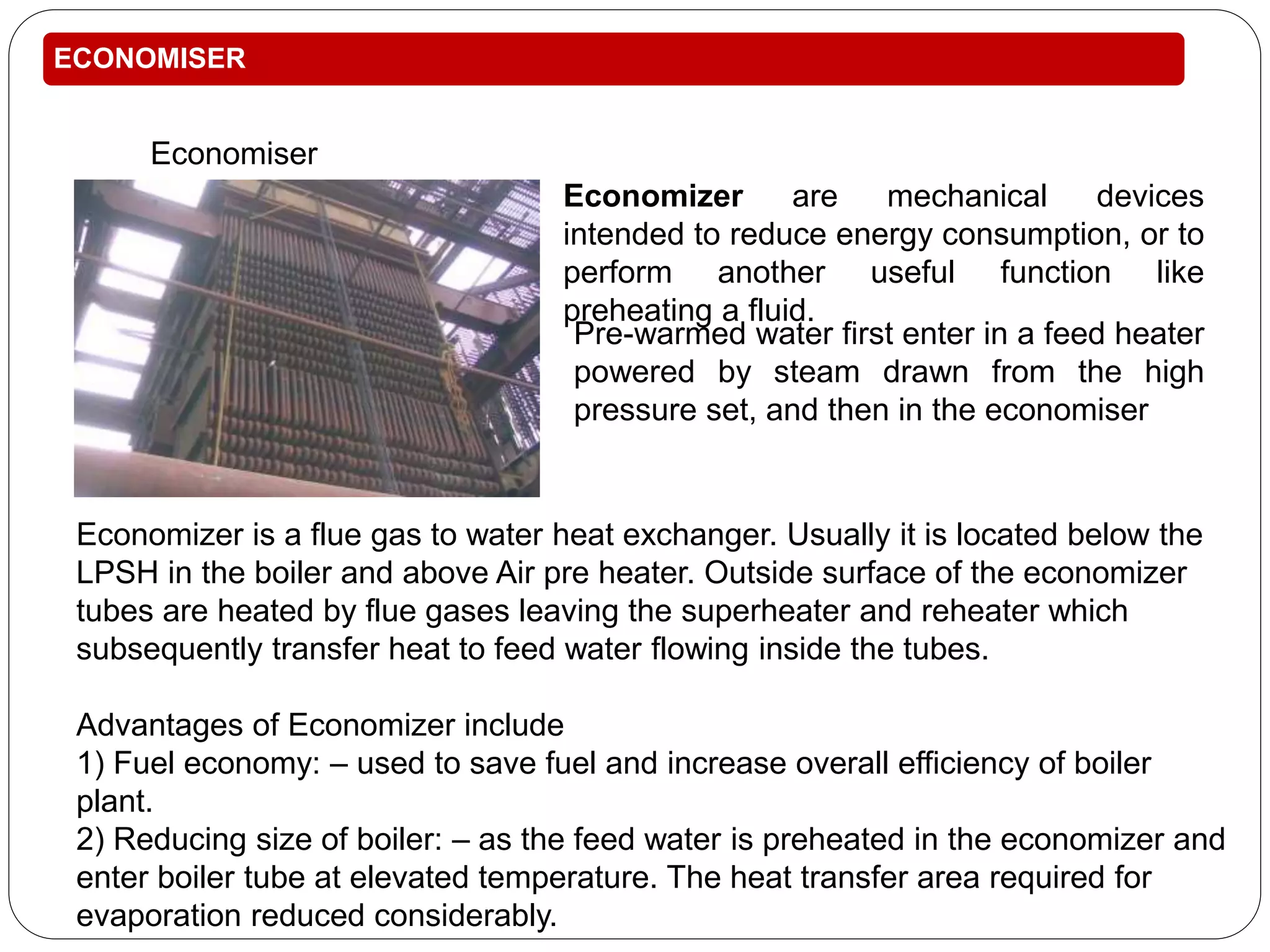


This training report summarizes the Panipat Thermal Power Station, which has a total generation capacity of 1360MW constructed in 5 stages from 110MW units to 250MW units. It describes the basic process of electricity generation including coal feeding, pulverization, combustion in the boiler, steam generation, superheating, steam turbine generation, and condensing. It provides details on the key elements of the plant including the deaerator, boiler feed pump, economizer, air preheater, boiler, superheater, turbine, and condenser. It also summarizes the instrumentation used for temperature, pressure, and process control.


