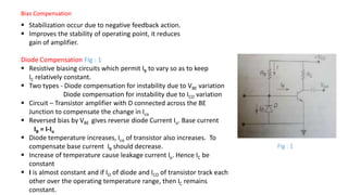
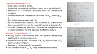
Bias Compensation
 Stabilization occur due to negative feedback action.
 Improves the stability of operating point, it reduces
gain of amplifier.
Diode Compensation Fig : 1
 Resistive biasing circuits which permit IB to vary so as to keep
IC relatively constant.
 Two types - Diode compensation for instability due to VBE variation
Diode compensation for instability due to ICO variation
 Circuit – Transistor amplifier with D connected across the BE
Junction to compensate the change in Ico
 Reversed bias by VBE gives reverse diode Current Io. Base current
IB = I-Io
 Diode temperature increases, Ico of transistor also increases. To
compensate base current IB should decrease.
 Increase of temperature cause leakage current Io. Hence IC be
constant
 I is almost constant and if IO of diode and ICO of transistor track each
other over the operating temperature range, then IC remains
constant.
Fig : 1
Thermistor Compensation Fig : 2
 Temperature sensitive device.
 RT, negative temperature coefficient connected in parallel with R2
 Resistance of a thermistor decreases when the temperature
increases.
 Increases when the temperature decreases the VBE, reducing IB ,
IC
 Bias Stabilization provided by RE, CE.
 As the temperature increases, the resistance RT of thermistor
decreases, which increases the current through it and resistor RE.
 Thus the temperature sensitivity of thermistor compensates the
increase in collector current, occurred due to temperature.
Sensistor Compensation Fig : 3
 Heavily doped semiconductor that has positive temperature
coefficient RS connected across R1.
 Temperature increases , resistance of R1, RS also increases – VBE
decreases, Reducing IB, IC
 Reduced IC, compensates for increased IC,
 Due to the increase in ICO, VBE and β due to temperature rise.
Fig : 2
Fig : 3

bias compensation.pptx

  • 1.
    Bias Compensation  Stabilizationoccur due to negative feedback action.  Improves the stability of operating point, it reduces gain of amplifier. Diode Compensation Fig : 1  Resistive biasing circuits which permit IB to vary so as to keep IC relatively constant.  Two types - Diode compensation for instability due to VBE variation Diode compensation for instability due to ICO variation  Circuit – Transistor amplifier with D connected across the BE Junction to compensate the change in Ico  Reversed bias by VBE gives reverse diode Current Io. Base current IB = I-Io  Diode temperature increases, Ico of transistor also increases. To compensate base current IB should decrease.  Increase of temperature cause leakage current Io. Hence IC be constant  I is almost constant and if IO of diode and ICO of transistor track each other over the operating temperature range, then IC remains constant. Fig : 1
  • 2.
    Thermistor Compensation Fig: 2  Temperature sensitive device.  RT, negative temperature coefficient connected in parallel with R2  Resistance of a thermistor decreases when the temperature increases.  Increases when the temperature decreases the VBE, reducing IB , IC  Bias Stabilization provided by RE, CE.  As the temperature increases, the resistance RT of thermistor decreases, which increases the current through it and resistor RE.  Thus the temperature sensitivity of thermistor compensates the increase in collector current, occurred due to temperature. Sensistor Compensation Fig : 3  Heavily doped semiconductor that has positive temperature coefficient RS connected across R1.  Temperature increases , resistance of R1, RS also increases – VBE decreases, Reducing IB, IC  Reduced IC, compensates for increased IC,  Due to the increase in ICO, VBE and β due to temperature rise. Fig : 2 Fig : 3