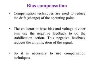
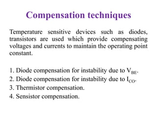
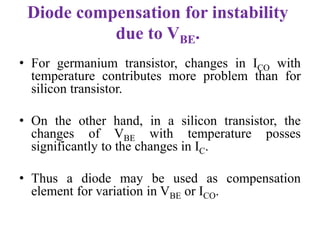
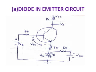
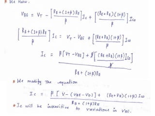
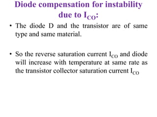
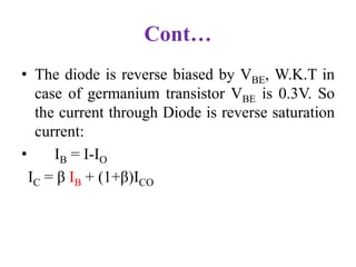
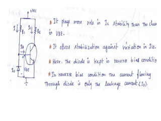
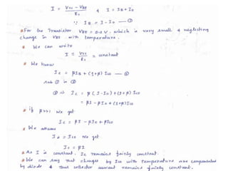
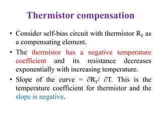
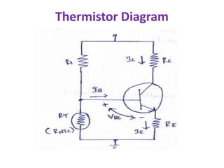
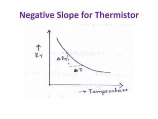
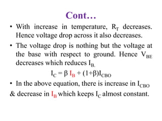
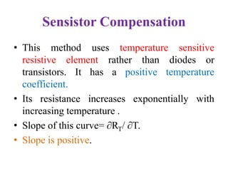
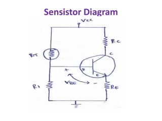
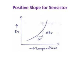
Bias compensation
R.Ramalakshmi
Assistant Professor
Ramco Institute of Technology
Rajapalayam
Bias compensation
• Compensation techniques are used to reduce
the drift (change) of the operating point.
• The collector to base bias and voltage divider
bias use the negative feedback to do the
stabilization action. This negative feedback
reduces the amplification of the signal.
• So it is necessary to use compensation
techniques.
Compensation techniques
Temperature sensitive devices such as diodes,
transistors are used which provide compensating
voltages and currents to maintain the operating point
constant.
1. Diode compensation for instability due to VBE.
2. Diode compensation for instability due to ICO.
3. Thermistor compensation.
4. Sensistor compensation.
Diode compensation for instability
due to VBE.
• For germanium transistor, changes in ICO with
temperature contributes more problem than for
silicon transistor.
• On the other hand, in a silicon transistor, the
changes of VBE with temperature posses
significantly to the changes in IC.
• Thus a diode may be used as compensation
element for variation in VBE or ICO.
Cont…
• In this case, the diode is kept forward biased
by the diode source VDD & Rd.
• If the diode and transistor are same material ,
the voltage across the diode will have the same
temperature co-efficient(-2.5 mv/c) as the VBE
• Apply KVL to the base circuit.
(a)DIODE IN EMITTER CIRCUIT
Diode compensation for instability
due to ICO:
• The diode D and the transistor are of same
type and same material.
• So the reverse saturation current ICO and diode
will increase with temperature at same rate as
the transistor collector saturation current ICO
Cont…
• The diode is reverse biased by VBE, W.K.T in
case of germanium transistor VBE is 0.3V. So
the current through Diode is reverse saturation
current:
• IB = I-IO
IC = β IB + (1+β)ICO
Thermistor compensation
• Consider self-bias circuit with thermistor RT as
a compensating element.
• The thermistor has a negative temperature
coefficient and its resistance decreases
exponentially with increasing temperature.
• Slope of the curve = ∂RT/ ∂T. This is the
temperature coefficient for thermistor and the
slope is negative.
Thermistor Diagram
Negative Slope for Thermistor
Cont…
• With increase in temperature, RT decreases.
Hence voltage drop across it also decreases.
• The voltage drop is nothing but the voltage at
the base with respect to ground. Hence VBE
decreases which reduces IB.
IC = β IB + (1+β)ICBO
• In the above equation, there is increase in ICBO
& decrease in IB which keeps IC almost constant.
Sensistor Compensation
• This method uses temperature sensitive
resistive element rather than diodes or
transistors. It has a positive temperature
coefficient.
• Its resistance increases exponentially with
increasing temperature .
• Slope of this curve= ∂RT/ ∂T.
• Slope is positive.
Sensistor Diagram
Cont…
• Resistor R1 can be replaced by sensistor element
RT in self- bias circuit.
• As temperature increases, RT increases which
decrease the current flowing through it. Hence
current through R2 decreases which reduces the
voltage drop across it.
• The voltage drop R2 is the voltage at the base with
respect to ground. Hence VBE decreases which
reduces IB.
Positive Slope for Sensistor
REFERENCES
• 1. Donald. A. Neamen, Electronic Circuits
Analysis and Design, 3rd Edition, Mc Graw Hill
Education (India) Private Ltd., 2010.
• 2. Robert L. Boylestad and Louis Nasheresky,
―Electronic Devices and Circuit Theory, 11th
Edition, Pearson Education, 2013.
Thank You

Bias compensation

  • 1.
  • 2.
    Bias compensation • Compensationtechniques are used to reduce the drift (change) of the operating point. • The collector to base bias and voltage divider bias use the negative feedback to do the stabilization action. This negative feedback reduces the amplification of the signal. • So it is necessary to use compensation techniques.
  • 3.
    Compensation techniques Temperature sensitivedevices such as diodes, transistors are used which provide compensating voltages and currents to maintain the operating point constant. 1. Diode compensation for instability due to VBE. 2. Diode compensation for instability due to ICO. 3. Thermistor compensation. 4. Sensistor compensation.
  • 4.
    Diode compensation forinstability due to VBE. • For germanium transistor, changes in ICO with temperature contributes more problem than for silicon transistor. • On the other hand, in a silicon transistor, the changes of VBE with temperature posses significantly to the changes in IC. • Thus a diode may be used as compensation element for variation in VBE or ICO.
  • 5.
    Cont… • In thiscase, the diode is kept forward biased by the diode source VDD & Rd. • If the diode and transistor are same material , the voltage across the diode will have the same temperature co-efficient(-2.5 mv/c) as the VBE • Apply KVL to the base circuit.
  • 6.
  • 8.
    Diode compensation forinstability due to ICO: • The diode D and the transistor are of same type and same material. • So the reverse saturation current ICO and diode will increase with temperature at same rate as the transistor collector saturation current ICO
  • 9.
    Cont… • The diodeis reverse biased by VBE, W.K.T in case of germanium transistor VBE is 0.3V. So the current through Diode is reverse saturation current: • IB = I-IO IC = β IB + (1+β)ICO
  • 12.
    Thermistor compensation • Considerself-bias circuit with thermistor RT as a compensating element. • The thermistor has a negative temperature coefficient and its resistance decreases exponentially with increasing temperature. • Slope of the curve = ∂RT/ ∂T. This is the temperature coefficient for thermistor and the slope is negative.
  • 13.
  • 14.
  • 15.
    Cont… • With increasein temperature, RT decreases. Hence voltage drop across it also decreases. • The voltage drop is nothing but the voltage at the base with respect to ground. Hence VBE decreases which reduces IB. IC = β IB + (1+β)ICBO • In the above equation, there is increase in ICBO & decrease in IB which keeps IC almost constant.
  • 16.
    Sensistor Compensation • Thismethod uses temperature sensitive resistive element rather than diodes or transistors. It has a positive temperature coefficient. • Its resistance increases exponentially with increasing temperature . • Slope of this curve= ∂RT/ ∂T. • Slope is positive.
  • 17.
  • 18.
    Cont… • Resistor R1can be replaced by sensistor element RT in self- bias circuit. • As temperature increases, RT increases which decrease the current flowing through it. Hence current through R2 decreases which reduces the voltage drop across it. • The voltage drop R2 is the voltage at the base with respect to ground. Hence VBE decreases which reduces IB.
  • 19.
  • 20.
    REFERENCES • 1. Donald.A. Neamen, Electronic Circuits Analysis and Design, 3rd Edition, Mc Graw Hill Education (India) Private Ltd., 2010. • 2. Robert L. Boylestad and Louis Nasheresky, ―Electronic Devices and Circuit Theory, 11th Edition, Pearson Education, 2013.
  • 21.