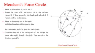
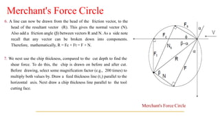
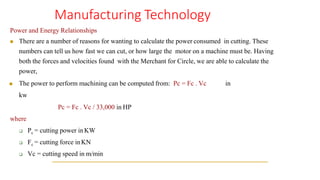
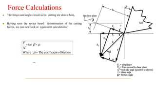
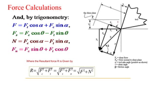
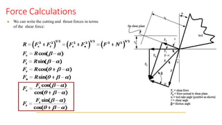
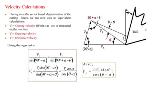
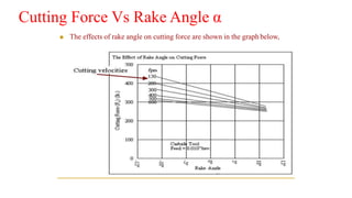
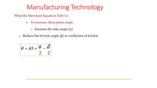
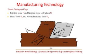
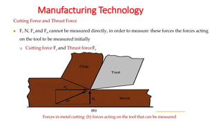
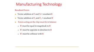
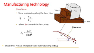
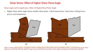
Merchant’s circle diagram
Dr. V.Harinadh
Dept of Mechanical Engineering
◼ Merchant's Force Circle is a method for calculating the
various forces involved in the cutting process.
1. Set up x-y axis labeled with forces, and the origin in the
centre of the page. The scale should be enough to include
both the measured forces. The cutting force (Fc) is drawn
horizontally, and the tangential force (Ft) is drawn
vertically. (These forces will all be in the lower left hand
quadrant).
Merchant's Force Circle
2. Draw in the resultant (R) of Fc and Ft.
3. Locate the centre of R, and draw a circle that encloses
vector R. If done correctly, the heads and tails of all 3
vectors will lie on this circle.
4. Draw in the cutting tool in the upper
right hand quadrant, taking care to draw
the correct rake angle (α) from the vertical axis.
5. Extend the line that is the cutting face of the tool (at the
same rake angle) through the circle. This now gives the
friction vector (F).
Merchant's Force Circle
6. A line can now be drawn from the head of the friction vector, to the
head of the resultant vector (R). This gives the normal vector (N).
Also add a friction angle (β) between vectors R and N. As a side note
recall that any vector can be broken down into components.
Therefore, mathematically, R = Fc + Ft = F + N.
7. We next use the chip thickness, compared to the cut depth to find the
shear force. To do this, the chip is drawn on before and after cut.
Before drawing, select some magnification factor (e.g., 200 times) to
multiply both values by. Draw a feed thickness line (t1) parallel to the
horizontal axis. Next draw a chip thickness line parallel to the tool
cutting face.
Merchant's Force Circle
8. Draw a vector from the origin (tool point) towards the intersection of
the two chip lines, stopping at the circle. The result will be a shear
force vector (Fs). Also measure the shear force angle between Fs and
Fc.
9. Finally add the shear force normal (Fn) from the head of Fs to the
head ofR.
10. Use a scale and protractor to measure off all distances (forces) and
angles.
Merchant's Force Circle
Manufacturing Technology
Power and Energy Relationships
◼ There are a number of reasons for wanting to calculate the power consumed in cutting. These
numbers can tell us how fast we can cut, or how large the motor on a machine must be. Having
both the forces and velocities found with the Merchant for Circle, we are able to calculate the
power,
◼ The power to perform machining can be computed from: Pc = Fc . Vc in
kw
Pc = Fc . Vc / 33,000 in HP
where
❑ Pc = cutting power inKW
❑ Fc = cutting force inKN
❑ Vc = cutting speed in m/min
Manufacturing Technology
Power and Energy Relationships
◼ Gross power to operate the machine tool Pg or HPg is given by
where
❑ E = mechanical efficiency of machine tool
❑ Typical E for machine tools  90%
◼ There are losses in the machine that must be considered when estimating the size of the electric motor
required:
Where
❑ Pt = power required to run the machine at no-load conditions (hp or kW)
g
Pc
E
P = or
g t
P =
Pc
E
+ P
g
H P =
H P c
E
Force Calculations
◼ The forces and angles involved in cutting are drawn here,
◼ Having seen the vector based determination of the cutting
forces, we can now look at equivalent calculations:
F
= tan = 
N
Where = The coefficient offriction
Force Calculations
Where the Resultant force R is Given by
R= F2
+F2
= F2
+F2
=
c t s n
F2
+N2
Force Calculations
◼ We can write the cutting and thrust forces in terms
of the shear force:
( )
o
Vs
c c
s
Vc
V cos
=
sin(90o
−) sin(90o
+−)
V sin 90 −
V = =
cos(−)
sin(90o
+−)
A ls o ,
f
V =
 Vc s i n 
c o s ( −  )
Velocity Calculations
◼ Having seen the vector based determination of the
cutting forces, we can now look at equivalent
calculations:
◼ Vc= Cutting velocity (ft/min) as set or measured
on the machine
◼ Vs= Shearing velocity
◼ Vf= Frictional velocity
Usingthe sign rules:
Cutting Force Vs Rake Angle α
◼ The effects of rake angle on cutting force are shown in the graph below,
Manufacturing Technology
The Merchant Equation
▪ To determine θ he assumed the minimum energy principle applied in metal cutting
so that the deformation process adjusted itself to a minimum energy condition.
◼ Of all the possible angles at which shear deformation can occur, the work material
will select a shear plane angle θ that minimizes energy, given by
 = 45 +
 −

2 2
❑ Derived by Eugene Merchant
Manufacturing Technology
What the Merchant Equation Tells Us
◼ To increase shear plane angle
❑ Increase the rake angle ()
❑ Reduce the friction angle (β) or coefficient of friction
 = 45 +
 −

2 2
Manufacturing Technology
Power and Energy Relationships
◼ Useful to convert power into power per unit volume rate of metal cut (power to cut one cubic inch per
minute)
◼ Called unit power, Pu or unit horsepower,HPu
◼ where RMR = material removalrate
U
Pc
M R
R
P = or U
H P
R
=
HPc
M R
Manufacturing Technology
Power and Energy Relationships
▪ Unit power is also known as the specific energy U
◼ Units for specific energy are typically N-m/mm3 or J/mm3 (in-lb/in3)
◼ Specific energy is in fact pressure and sometimes is called specific cutting
pressure:
1
u
MR c 1
Fc
Pc Fc Vc
U = P = = =
R V t  w t  w
F c
A
U =
Force & Velocity Relationships and
the Merchant Equation
Manufacturing Technology
Forces Acting on Chip
◼ Friction force F and Normal force to friction N
◼ Shear force Fs and Normal force to shearFn
Forces in metal cutting: (a) forces acting on the chip in orthogonal cutting
Manufacturing Technology
Cutting Force and Thrust Force
◼ F, N, Fs and Fn cannot be measured directly, in order to measure these forces the forces acting
on the tool to be measured initially
❑ Cutting force Fc and Thrust forceFt
Forces in metal cutting: (b) forces acting on the tool that can be measured
Manufacturing Technology
Resultant Forces
◼ Vector addition of F and N = resultant R
◼ Vector addition of Fs and Fn = resultant R'
◼ Forces acting on the chip must be in balance:
❑ R' must be equal in magnitude to R
❑ R’ must be opposite in direction to R
❑ R’ must be collinear with R
Manufacturing Technology
Shear Stress
▪ Shear stress acting along the shear plane
▪ where As = area of the shear plane
▪ Shear stress = shear strength of work material during cutting
A s
F s
S =
s
t1w
sin
A =
Shear Stress- Effect of Higher Shear Plane Angle
Shear angle and its significance Effect of Higher Shear Plane Angle
◼ Higher shear plane angle means smaller shear plane which means lower shear force, cutting forces,
power, and temperature
Effect of shear plane angle  : (a) higher θ with a resulting lower shear plane area; (b) smaller θ with a corresponding larger shear
plane area. Note that the rake angle is larger in (a), which tends to increase shear angle according to the Merchant equation
Manufacturing Technology
Cutting Temperature
▪ Approximately 98% of the energy in machining is converted into heat
▪ This can cause temperatures to be very high at the tool-chip
▪ The remaining energy (about 2%) is retained as elastic energy in the chip
High cutting temperatures
▪ Reduce tool life
▪ Produce hot chips that pose safety hazards to the machine operator
▪ Can cause inaccuracies in part dimensions due to thermal expansion of work material
Manufacturing Technology
Process Parameters
◼ Speed (v), Feed (f), Depth of Cut (d)
◼ Material Removal Rate (MRR) = f x d x v
Manufacturing Technology
• Shear angle and its significance
▪ Shear angle(θ) is the angle made by the shear plane with the cutting
speed vector.
▪ Shear angle is very important parameter I metal cutting.
• Higher the shear angle, better is the cutting performance.
▪ In metal cutting it is observed that a higher rake angles give rise to
higher shear angles

4.Merchant’s circle diagram.pdf

  • 1.
    Merchant’s circle diagram Dr.V.Harinadh Dept of Mechanical Engineering
  • 2.
    ◼ Merchant's ForceCircle is a method for calculating the various forces involved in the cutting process. 1. Set up x-y axis labeled with forces, and the origin in the centre of the page. The scale should be enough to include both the measured forces. The cutting force (Fc) is drawn horizontally, and the tangential force (Ft) is drawn vertically. (These forces will all be in the lower left hand quadrant). Merchant's Force Circle Merchant's Force Circle
  • 3.
    2. Draw inthe resultant (R) of Fc and Ft. 3. Locate the centre of R, and draw a circle that encloses vector R. If done correctly, the heads and tails of all 3 vectors will lie on this circle. 4. Draw in the cutting tool in the upper right hand quadrant, taking care to draw the correct rake angle (α) from the vertical axis. 5. Extend the line that is the cutting face of the tool (at the same rake angle) through the circle. This now gives the friction vector (F). Merchant's Force Circle Merchant's Force Circle
  • 4.
    6. A linecan now be drawn from the head of the friction vector, to the head of the resultant vector (R). This gives the normal vector (N). Also add a friction angle (β) between vectors R and N. As a side note recall that any vector can be broken down into components. Therefore, mathematically, R = Fc + Ft = F + N. 7. We next use the chip thickness, compared to the cut depth to find the shear force. To do this, the chip is drawn on before and after cut. Before drawing, select some magnification factor (e.g., 200 times) to multiply both values by. Draw a feed thickness line (t1) parallel to the horizontal axis. Next draw a chip thickness line parallel to the tool cutting face. Merchant's Force Circle Merchant's Force Circle
  • 5.
    8. Draw avector from the origin (tool point) towards the intersection of the two chip lines, stopping at the circle. The result will be a shear force vector (Fs). Also measure the shear force angle between Fs and Fc. 9. Finally add the shear force normal (Fn) from the head of Fs to the head ofR. 10. Use a scale and protractor to measure off all distances (forces) and angles. Merchant's Force Circle Merchant's Force Circle
  • 6.
    Manufacturing Technology Power andEnergy Relationships ◼ There are a number of reasons for wanting to calculate the power consumed in cutting. These numbers can tell us how fast we can cut, or how large the motor on a machine must be. Having both the forces and velocities found with the Merchant for Circle, we are able to calculate the power, ◼ The power to perform machining can be computed from: Pc = Fc . Vc in kw Pc = Fc . Vc / 33,000 in HP where ❑ Pc = cutting power inKW ❑ Fc = cutting force inKN ❑ Vc = cutting speed in m/min
  • 7.
    Manufacturing Technology Power andEnergy Relationships ◼ There are a number of reasons for wanting to calculate the power consumed in cutting. These numbers can tell us how fast we can cut, or how large the motor on a machine must be. Having both the forces and velocities found with the Merchant for Circle, we are able to calculate the power, ◼ The power to perform machining can be computed from: Pc = Fc . Vc in kw Pc = Fc . Vc / 33,000 in HP where ❑ Pc = cutting power inKW ❑ Fc = cutting force inKN ❑ Vc = cutting speed in m/min
  • 8.
    Manufacturing Technology Power andEnergy Relationships ◼ Gross power to operate the machine tool Pg or HPg is given by where ❑ E = mechanical efficiency of machine tool ❑ Typical E for machine tools  90% ◼ There are losses in the machine that must be considered when estimating the size of the electric motor required: Where ❑ Pt = power required to run the machine at no-load conditions (hp or kW) g Pc E P = or g t P = Pc E + P g H P = H P c E
  • 9.
    Force Calculations ◼ Theforces and angles involved in cutting are drawn here, ◼ Having seen the vector based determination of the cutting forces, we can now look at equivalent calculations: F = tan =  N Where = The coefficient offriction
  • 10.
    Force Calculations Where theResultant force R is Given by R= F2 +F2 = F2 +F2 = c t s n F2 +N2
  • 11.
    Force Calculations ◼ Wecan write the cutting and thrust forces in terms of the shear force:
  • 12.
    ( ) o Vs c c s Vc Vcos = sin(90o −) sin(90o +−) V sin 90 − V = = cos(−) sin(90o +−) A ls o , f V =  Vc s i n  c o s ( −  ) Velocity Calculations ◼ Having seen the vector based determination of the cutting forces, we can now look at equivalent calculations: ◼ Vc= Cutting velocity (ft/min) as set or measured on the machine ◼ Vs= Shearing velocity ◼ Vf= Frictional velocity Usingthe sign rules:
  • 13.
    Cutting Force VsRake Angle α ◼ The effects of rake angle on cutting force are shown in the graph below,
  • 14.
    Manufacturing Technology The MerchantEquation ▪ To determine θ he assumed the minimum energy principle applied in metal cutting so that the deformation process adjusted itself to a minimum energy condition. ◼ Of all the possible angles at which shear deformation can occur, the work material will select a shear plane angle θ that minimizes energy, given by  = 45 +  −  2 2 ❑ Derived by Eugene Merchant
  • 15.
    Manufacturing Technology What theMerchant Equation Tells Us ◼ To increase shear plane angle ❑ Increase the rake angle () ❑ Reduce the friction angle (β) or coefficient of friction  = 45 +  −  2 2
  • 16.
    Manufacturing Technology Power andEnergy Relationships ◼ Useful to convert power into power per unit volume rate of metal cut (power to cut one cubic inch per minute) ◼ Called unit power, Pu or unit horsepower,HPu ◼ where RMR = material removalrate U Pc M R R P = or U H P R = HPc M R
  • 17.
    Manufacturing Technology Power andEnergy Relationships ▪ Unit power is also known as the specific energy U ◼ Units for specific energy are typically N-m/mm3 or J/mm3 (in-lb/in3) ◼ Specific energy is in fact pressure and sometimes is called specific cutting pressure: 1 u MR c 1 Fc Pc Fc Vc U = P = = = R V t  w t  w F c A U =
  • 18.
    Force & VelocityRelationships and the Merchant Equation
  • 19.
    Manufacturing Technology Forces Actingon Chip ◼ Friction force F and Normal force to friction N ◼ Shear force Fs and Normal force to shearFn Forces in metal cutting: (a) forces acting on the chip in orthogonal cutting
  • 20.
    Manufacturing Technology Cutting Forceand Thrust Force ◼ F, N, Fs and Fn cannot be measured directly, in order to measure these forces the forces acting on the tool to be measured initially ❑ Cutting force Fc and Thrust forceFt Forces in metal cutting: (b) forces acting on the tool that can be measured
  • 21.
    Manufacturing Technology Resultant Forces ◼Vector addition of F and N = resultant R ◼ Vector addition of Fs and Fn = resultant R' ◼ Forces acting on the chip must be in balance: ❑ R' must be equal in magnitude to R ❑ R’ must be opposite in direction to R ❑ R’ must be collinear with R
  • 22.
    Manufacturing Technology Shear Stress ▪Shear stress acting along the shear plane ▪ where As = area of the shear plane ▪ Shear stress = shear strength of work material during cutting A s F s S = s t1w sin A =
  • 23.
    Shear Stress- Effectof Higher Shear Plane Angle Shear angle and its significance Effect of Higher Shear Plane Angle ◼ Higher shear plane angle means smaller shear plane which means lower shear force, cutting forces, power, and temperature Effect of shear plane angle  : (a) higher θ with a resulting lower shear plane area; (b) smaller θ with a corresponding larger shear plane area. Note that the rake angle is larger in (a), which tends to increase shear angle according to the Merchant equation
  • 24.
    Manufacturing Technology Cutting Temperature ▪Approximately 98% of the energy in machining is converted into heat ▪ This can cause temperatures to be very high at the tool-chip ▪ The remaining energy (about 2%) is retained as elastic energy in the chip High cutting temperatures ▪ Reduce tool life ▪ Produce hot chips that pose safety hazards to the machine operator ▪ Can cause inaccuracies in part dimensions due to thermal expansion of work material
  • 25.
    Manufacturing Technology Process Parameters ◼Speed (v), Feed (f), Depth of Cut (d) ◼ Material Removal Rate (MRR) = f x d x v
  • 26.
    Manufacturing Technology • Shearangle and its significance ▪ Shear angle(θ) is the angle made by the shear plane with the cutting speed vector. ▪ Shear angle is very important parameter I metal cutting. • Higher the shear angle, better is the cutting performance. ▪ In metal cutting it is observed that a higher rake angles give rise to higher shear angles