Downloaded 108 times

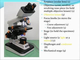
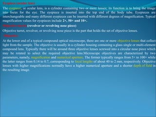


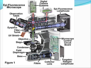


The document is a detailed overview of the components and principles of optical microscopes, discussing parts such as the eyepiece, objective lenses, and focus knobs, as well as the processes of magnification and resolution. It explains various types of microscopy techniques, including bright field, phase contrast, and fluorescence microscopy, and highlights the importance of proper illumination and maintenance of the microscope for effective observation. Additionally, it addresses the characteristics and costs associated with different objective lenses, particularly achromat and apochromat lenses.