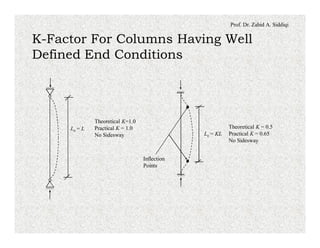
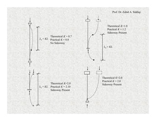
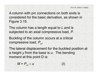
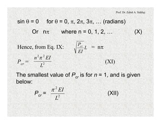
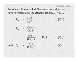
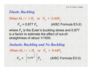
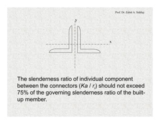
This document discusses compression members and buckling of steel columns. It defines compression members as members subjected to compressive stresses that tend to shorten or squeeze the member. Examples given include struts, columns, truss chords, and beams. It notes that compression members are more prone to buckling than tension members. Buckling occurs when the critical buckling load is reached due to factors like member length, cross-section, end conditions, and imperfections. The effective length factor K is introduced to account for end conditions and sidesway in calculating the critical slenderness ratio.
Analysis and Design of Structural Components of a Ten Storied RCC Residential...Shariful Haque Robin
This report has been prepared as an integral part of the internship program for the Bachelor of Science in Civil Engineering (BSCE) under the Department of Civil Engineering in IUBAT−International University of Business Agriculture and Technology. The Dynamic Design and Development (DDD) Ltd. nominated as the organization for the practicum while honorable Prof. Dr. Md. Monirul Islam, Chair of the Department of Civil Engineering rendered his kind consent to academically supervise the internship program.
information on types of beams, different methods to calculate beam stress, design for shear, analysis for SRB flexure, design for flexure, Design procedure for doubly reinforced beam,
Design of water tank (RCC design) By Working Stress Method as per Indian Standards.
Useful for Practicing Civil Engineers & Students of B.Tech & B.E in civil
This document gives the class notes of Unit 5 shear force and bending moment in beams. Subject: Mechanics of materials.
Syllabus contest is as per VTU, Belagavi, India.
Notes Compiled By: Hareesha N Gowda, Assistant Professor, DSCE, Bengaluru-78.
Forklift Classes Overview by Intella PartsIntella Parts
Discover the different forklift classes and their specific applications. Learn how to choose the right forklift for your needs to ensure safety, efficiency, and compliance in your operations.
For more technical information, visit our website https://intellaparts.com
Hierarchical Digital Twin of a Naval Power SystemKerry Sado
A hierarchical digital twin of a Naval DC power system has been developed and experimentally verified. Similar to other state-of-the-art digital twins, this technology creates a digital replica of the physical system executed in real-time or faster, which can modify hardware controls. However, its advantage stems from distributing computational efforts by utilizing a hierarchical structure composed of lower-level digital twin blocks and a higher-level system digital twin. Each digital twin block is associated with a physical subsystem of the hardware and communicates with a singular system digital twin, which creates a system-level response. By extracting information from each level of the hierarchy, power system controls of the hardware were reconfigured autonomously. This hierarchical digital twin development offers several advantages over other digital twins, particularly in the field of naval power systems. The hierarchical structure allows for greater computational efficiency and scalability while the ability to autonomously reconfigure hardware controls offers increased flexibility and responsiveness. The hierarchical decomposition and models utilized were well aligned with the physical twin, as indicated by the maximum deviations between the developed digital twin hierarchy and the hardware.
CW RADAR, FMCW RADAR, FMCW ALTIMETER, AND THEIR PARAMETERSveerababupersonal22
It consists of cw radar and fmcw radar ,range measurement,if amplifier and fmcw altimeterThe CW radar operates using continuous wave transmission, while the FMCW radar employs frequency-modulated continuous wave technology. Range measurement is a crucial aspect of radar systems, providing information about the distance to a target. The IF amplifier plays a key role in signal processing, amplifying intermediate frequency signals for further analysis. The FMCW altimeter utilizes frequency-modulated continuous wave technology to accurately measure altitude above a reference point.
Cosmetic shop management system project report.pdfKamal Acharya
Buying new cosmetic products is difficult. It can even be scary for those who have sensitive skin and are prone to skin trouble. The information needed to alleviate this problem is on the back of each product, but it's thought to interpret those ingredient lists unless you have a background in chemistry.
Instead of buying and hoping for the best, we can use data science to help us predict which products may be good fits for us. It includes various function programs to do the above mentioned tasks.
Data file handling has been effectively used in the program.
The automated cosmetic shop management system should deal with the automation of general workflow and administration process of the shop. The main processes of the system focus on customer's request where the system is able to search the most appropriate products and deliver it to the customers. It should help the employees to quickly identify the list of cosmetic product that have reached the minimum quantity and also keep a track of expired date for each cosmetic product. It should help the employees to find the rack number in which the product is placed.It is also Faster and more efficient way.
The Internet of Things (IoT) is a revolutionary concept that connects everyday objects and devices to the internet, enabling them to communicate, collect, and exchange data. Imagine a world where your refrigerator notifies you when you’re running low on groceries, or streetlights adjust their brightness based on traffic patterns – that’s the power of IoT. In essence, IoT transforms ordinary objects into smart, interconnected devices, creating a network of endless possibilities.
Here is a blog on the role of electrical and electronics engineers in IOT. Let's dig in!!!!
For more such content visit: https://nttftrg.com/
Harnessing WebAssembly for Real-time Stateless Streaming PipelinesChristina Lin
Traditionally, dealing with real-time data pipelines has involved significant overhead, even for straightforward tasks like data transformation or masking. However, in this talk, we’ll venture into the dynamic realm of WebAssembly (WASM) and discover how it can revolutionize the creation of stateless streaming pipelines within a Kafka (Redpanda) broker. These pipelines are adept at managing low-latency, high-data-volume scenarios.
Harnessing WebAssembly for Real-time Stateless Streaming Pipelines
Steel strucure lec # (6)
1. Prof. Dr. Zahid A. Siddiqi
COMPRESSION MEMBERS
When a load tends to squeeze or shorten a
member, the stresses produced are said to be
compressive in nature and the member is called a
compression member (Figure 3.1).
Examples are struts (short compression members
without chances of buckling), eccentrically loaded
columns, top chords of trusses, bracing members,
compression flanges of beams and members that
are subjected simultaneously to bending and
compressive loads.
2. Prof. Dr. Zahid A. Siddiqi
P
P
There are two significant differences
between the behavior of tension and
compression members, as under:
1. The tensile loads tend to hold
a member straight even if the
member is not initially in one line
and is subjected to simultaneous
bending moments.
In contrast, the compressive loads tend to bend
the member out of the plane of the loads due to
imperfections, simultaneous bending moment or
even without all of these.
3. Prof. Dr. Zahid A. Siddiqi
Tests on majority of practical columns show that
they will fail at axial stresses well below the
elastic limit of the column material because of
their tendency to buckle (which is a sudden
lateral bending due to a critical compressive
force).
For these reasons, the strength of compression
members is reduced in relation to the danger of
buckling depending on length of column, end
conditions and cross-sectional dimensions.
4. Prof. Dr. Zahid A. Siddiqi
The longer a column becomes for the same cross-
section the greater is its tendency to buckle and
the smaller is the load it will support.
When the length of a compression member
increases relative to its cross-section, it may
buckle at a lower load.
After buckling the load cannot be sustained and
the load capacity nearly approaches zero.
The condition of a column at its critical buckling
load is that of an unstable equilibrium as shown in
Figure 3.2.
5. Prof. Dr. Zahid A. Siddiqi
(a) Stable (b) Neutral (c) Unstable
Figure 3.2. Types of Equilibrium States.
In the first case, the restoring forces are greater
than the forces tending to upset the system.
Due to an infinitesimal small displacement
consistent with the boundary conditions or due to
small imperfection of a column, a moment is
produced in a column trying to bend it.
6. Prof. Dr. Zahid A. Siddiqi
At the same time, due to stress in the material,
restoring forces are also developed to bring the
column back to its original shape.
If restoring force is greater than the upsetting
moment, the system is stable but if restoring force
is lesser than the upsetting moment, the system
is unstable.
Right at the transition point when restoring force
is exactly equal to the upsetting moment, we get
neutral equilibrium.
The force associated with this condition is the
critical or buckling load.
7. Prof. Dr. Zahid A. Siddiqi
2. The presence of rivet or bolt holes in tension
members reduces the area available for resisting
loads; but in compression members the rivets or
bolts are assumed to fill the holes and the entire
gross area is available for resisting load.
CONCENTRICALLY AND ECCENTRICALLY
LOADED COLUMNS
The ideal type of load on a column is a concentric
load and the member subjected to this type of load
is called concentrically loaded column.
8. Prof. Dr. Zahid A. Siddiqi
The load is distributed uniformly over the entire
cross-section with the center of gravity of the
loads coinciding with the center of gravity of the
columns.
Due to load patterns, the live load on slabs and
beams may not be concentrically transferred to
interior columns.
Similarly, the dead and live loads transferred to
the exterior columns are, generally, having large
eccentricities, as the center of gravity of the loads
will usually fall well on the inner side of the
column.
9. Prof. Dr. Zahid A. Siddiqi
In practice, majority of the columns are
eccentrically loaded compression members
Slight initial crookedness, eccentricity of loads, and
application of simultaneous transverse loads
produce significant bending moments as the
product of high axial loads (P) multiplied with the
eccentricity, e.
This moment, P ´ e, facilitates buckling and
reduces the load carrying capacity.
Eccentricity, e, may be relatively smaller, but the
product (P ´ e) may be significantly larger.
10. Prof. Dr. Zahid A. Siddiqi
P
a) Initial
Crookedness
Pe
Pe
b) Eccentric Load
P
P
c)Simultaneous
Transverse Load
11. Prof. Dr. Zahid A. Siddiqi
The AISC Code of Standard Practice specifies an
acceptable upper limit on the out-of-plumbness and
initial crookedness equal to the length of the
member divided by 500 (equal to 0.002, AISC C2-
2b-3).
RESIDUAL STRESSES
Residual stresses are stresses that remain in a
member after it has been formed into a finished
product.
These are always present in a member even
without the application of loads.
12. Prof. Dr. Zahid A. Siddiqi
The magnitudes of these stresses are
considerably high and, in some cases, are
comparable to the yield stresses (refer to Figure
3.4).
The causes of presence of residual stresses are
as under:
1. Uneven cooling which occurs after hot rolling
of structural shapes produces thermal stresses,
which are permanently stored in members.
The thicker parts cool at the end, and try to shorten
in length.
13. Prof. Dr. Zahid A. Siddiqi
While doing so they produce compressive
stresses in the other parts of the section and
tension in them.
Overall magnitude of this tension and
compression remain equal for equilibrium.
In I-shape sections, after hot rolling, the thick
junction of flange to web cools more slowly than the
web and flange tips.
Consequently, compressive residual stress exists at
flange tips and at mid-depth of the web (the regions
that cool fastest), while tensile residual stress exists
in the flange and the web at the regions where they
join.
14. Prof. Dr. Zahid A. Siddiqi
83 to 93 MPa
80 to 95 MPa
(C)
(T)
a)Rolled Shapes
(C)
(T)
(C)
80 to 95 MPa
» 0.3Fy for A36
(T)
80 to 95 MPa
15. Prof. Dr. Zahid A. Siddiqi
280 MPa (T)
84 MPa (C)
140 MPa (T)
140 MPa
(C)
240 MPa
(T)
140 MPa (C)
b)Welded Shapes
Weld
Weld
16. Prof. Dr. Zahid A. Siddiqi
2. Cold bending of members beyond their
elastic limit produce residual stresses and strains
within the members.
Similarly, during fabrication, if some member
having extra length is forced to fit between other
members, stresses are produced in the
associated members.
3. Punching of holes and cutting operations
during fabrication also produce residual stresses.
17. Prof. Dr. Zahid A. Siddiqi
4. Welding also produces the stresses due to
uneven cooling after welding.
Welded part will cool at the end inviting other
parts to contract with it.
This produces compressive stresses in parts
away from welds and tensile stresses in parts
closer to welds.
SECTIONS USED FOR COLUMNS
Single angle, double angle, tee, channel, W-
section, pipe, square tubing, and rectangular tubing
may be used as columns.
18. Prof. Dr. Zahid A. Siddiqi
Four Angles
Box Section
Two Inward
Channels Box
Section
Two Outward
Channels Box
Section
Built-Up
Box
W - Section
With Cover
Plates
Built-Up
I-Section
Built-Up
Rectangular
Box
W And Channels
Built-Up Section Built-Up I-Section
19. Prof. Dr. Zahid A. Siddiqi
Different combinations of these structural shapes
may also be employed for compression members
to get built-up sections as shown in Figure 3.5.
Built-up sections are better for columns because
the slenderness ratios in various directions may be
controlled to get nearly equal values in all the
directions.
This makes the column economical as far as the
material cost is concerned. However, the joining
and labor cost is generally higher for built-up
sections.
20. Prof. Dr. Zahid A. Siddiqi
The total cost of these sections may become less
for greater lengths.
The joining of various elements of a built-up
section is usually performed by using lacing.
LIMITING SLENDERNESS RATIO
The slenderness ratio of compression members
should preferably not exceed 200 (AISC E2).
This means that in exceptional cases, the limit
may be exceeded.
21. Prof. Dr. Zahid A. Siddiqi
INSTABILITY OF COLUMNS
B
A
C
Figure 3.6. Local Flange
Instability.
Local Instability
During local instability, the
individual parts or plate
elements of cross-section
buckle without overall
buckling of the column.
Width/thickness ratio of
each part gives the
slenderness ratio (l = b/t),
which controls the local
buckling.
27. Prof. Dr. Zahid A. Siddiqi
Local buckling should never be allowed to occur
before the overall buckling of the member except
in few cases like web of a plate girder.
An unstiffened element is a projecting piece with
one free edge parallel to the direction of the
compressive force.
The example is half flange AB in Figure 3.6.
A stiffened element is supported along the two
edges parallel to the direction of the force.
The example is web AC in the same figure.
28. Prof. Dr. Zahid A. Siddiqi
For unstiffened flange of figure, b is equal to half
width of flange (bf / 2) and t is equal to tf. Hence,
bf / 2tf ratio is used to find l.
For stiffened web, h is the width of web and tw is
the thickness of web and the corresponding value
of l or b/t ratio is h / tw, which controls web local
buckling.
Overall Instability
In case of overall instability, the column buckles as
a whole between the supports or the braces about
an axis whose corresponding slenderness ratio is
bigger.
30. Prof. Dr. Zahid A. Siddiqi
Buckling
about
major
axis.
a)Buckling about
major axis
a)Buckling about
minor axis
Figure - Buckling of a Column Without Intermediate Bracing
31. Prof. Dr. Zahid A. Siddiqi
Buckling
about
minor
axis
Bracing to
prevent major
axis buckling,
connected to
stable
structures
lx1
lx2
33. Prof. Dr. Zahid A. Siddiqi
Single angle sections may buckle about their weak
axis (z-axis, Figure 3.10).
Calculate Le / rz to check the slenderness ratio.
In general, all un-symmetric sections having non-
zero product moment of inertia (Ixy) have a weak
axis different from the y-axis.
Z
Z
Figure 3.10. Axis of Buckling For Single Angle Section.
34. Prof. Dr. Zahid A. Siddiqi
Unsupported Length
It is the length of column between two consecutive
supports or braces denoted by Lux or Luy in the x
and y directions, respectively.
A different value of unsupported length may exist in
different directions and must be used to calculate
the corresponding slenderness ratios.
To calculate unsupported length of a column in a
particular direction, only the corresponding supports
and braces are to be considered neglecting the
bracing preventing buckling in the other direction.
35. Prof. Dr. Zahid A. Siddiqi
Effective Length Of Column
The length of the column corresponding to one-
half sine wave of the buckled shape or the length
between two consecutive inflection points or
supports after buckling is called the effective
length.
BUCKLING OF STEEL COLUMNS
Buckling is the sudden lateral bending produced
by axial loads due to initial imperfection, out-of-
straightness, initial curvature, or bending produced
by simultaneous bending moments.
36. Prof. Dr. Zahid A. Siddiqi
Chances of buckling are directly related with the
slenderness ratio KL/r and hence there are three
parameters affecting buckling.
1. Effective length factor (K), which depends on the
end conditions of the column.
2. Unbraced length of column (Lu), in strong
direction or in weak direction, whichever gives
more answer for KL/r.
3. Radius of gyration (r), which may be rx or ry
(strong and weak direction) for uniaxially or
biaxially symmetrical cross-sections and least
radius of gyration (rz) for un-symmetrical cross-
sections like angle sections.
37. Prof. Dr. Zahid A. Siddiqi
Following points must be remembered to find the
critical slenderness ratio:
a. Buckling will take place about a direction for
which the corresponding slenderness ratio is
the maximum.
b. For unbraced compression members
consisting of angle section, the total length
and rz are used in the calculation of KL/r
ratio.
c. For steel braces, bracing is considered the
most effective if tension is produced in them
due to buckling.
38. Prof. Dr. Zahid A. Siddiqi
d. Braces that provide resistance by bending
are less effective and braces having
compression are almost ineffective because
of their small x-sections and longer lengths.
e. The brace is considered effective if its other
end is connected to a stable structure,
which is not undergoing buckling
simultaneously with the braced member.
f. The braces are usually provided inclined to
main members of steel structures starting
from mid-spans to ends of the adjacent
columns.
39. Prof. Dr. Zahid A. Siddiqi
g. Because bracing is most effective in
tension, it is usually provided on both sides
to prevent buckling on either side.
h. Bracing can be provided to prevent
buckling along weak axis. KL/r should be
calculated by using Ky, unbraced length
along weak axis and ry.
i. Bracing can also be provided to prevent
buckling along the strong axis. KL/r in this
case should be calculated by using Kx, the
unbraced length along strong axis and rx.
40. Prof. Dr. Zahid A. Siddiqi
j. The end condition of a particular
unsupported length of a column at an
intermediate brace is considered a hinge.
The reason is that the rotation becomes free
at this point and only the lateral movement is
prevented.
EFFECTIVE LENGTH FACTOR (K)
This factor gives the ratio of length of half sine
wave of deflected shape after buckling to full-
unsupported length of column.
41. Prof. Dr. Zahid A. Siddiqi
This depends upon the end conditions of the
column and the fact that whether sidesway is
permitted or not.
Greater the K-value, greater is the effective length
and slenderness ratio and hence smaller is the
buckling load.
K-value in case of no sidesway is between 0.5 and
1.0, whereas, in case of appreciable sidesway, it is
greater than or equal to 1.0
Le = K Lu
42. Prof. Dr. Zahid A. Siddiqi
Sidesway
Any appreciable lateral or sideward movement of
top of a vertical column relative to its bottom is
called sidesway, sway or lateral drift.
If sidesway is possible, k-value increases by a
greater degree and column buckles at a lesser
load.
Sidesway in a frame takes place due to:-
a. Lengths of different columns are unequal.
b. When sections of columns have different cross-
sectional properties.
43. Prof. Dr. Zahid A. Siddiqi
c. Loads are un-symmetrical.
d. Lateral loads are acting.
2II
I
(a) (b) (c) (d)
Figure 3.11. Causes of Sidesway in a Building Frame.
Sidesway may be prevented in a frame by:
a. Providing shear or partition walls.
44. Prof. Dr. Zahid A. Siddiqi
b. Fixing the top of frame with adjoining rigid
structures.
c. Provision of properly designed lift well or
shear walls in a building, which may act like
backbone of the structure reducing the
lateral deflections.
Shear wall is a structural wall that resists
shear forces resulting from the applied
transverse loads in its own plane and it
produces frame stability.
45. Prof. Dr. Zahid A. Siddiqi
Provision of lateral bracing, which may be of
following two types:
i. Diagonal bracing, and
ii. Longitudinal bracing.
Unbraced frame is defined as the one in which the
resistance to lateral load is provided by the bending
resistance of frame members and their connections
without any additional bracing.
46. Prof. Dr. Zahid A. Siddiqi
K-Factor For Columns Having Well
Defined End Conditions
Theoretical K=1.0
Practical K = 1.0
No Sidesway
Theoretical K = 0.5
Practical K = 0.65
No Sidesway
Inflection
Points
Le = L
Le = KL
47. Prof. Dr. Zahid A. Siddiqi
Theoretical K=2.0
Practical K = 2.10
Sidesway Present
Theoretical K=2.0
Practical K = 2.0
Sidesway Present
Le = KL
Theoretical K = 0.7
Practical K = 0.8
No Sidesway
Theoretical K=1.0
Practical K = 1.2
Sidesway Present
Le = KL
Le = KL
48. Prof. Dr. Zahid A. Siddiqi
Partially Restrained Columns
Consider the example of column AB shown in
Figure 3.13.
The ends are not free to rotate and are also not
perfectly fixed.
Instead these ends are partially fixed with the fixity
determined by the ratio of relative flexural stiffness
of columns meeting at a joint to the flexural
stiffness of beams meeting at that joint.
49. Prof. Dr. Zahid A. Siddiqi
y or G at each end =
( )
( )
EI of columns
EI of beams
l
l
å
å
A
B
B
GB or yB
A
GA or yA
Columns
Beams
Part-X
Column AB of Part-X
Figure 3.13. Partially restrained Columns.
50. Prof. Dr. Zahid A. Siddiqi
K-Values For Truss And
Braced Frame Members
The effective length factor, K, is considered equal
to 1.0 for members of the trusses and braced frame
columns.
In case the value is to be used less than one for
frame columns, detailed buckling analysis is
required to be carried out and bracing is to be
designed accordingly.
51. Prof. Dr. Zahid A. Siddiqi
ELASTIC BUCKLING LOAD
FOR LONG COLUMNS
P = Pcr
P = Pcr
umax.
uD
y
C
B
A
Buckled
Shape
L / 2
L / 2
52. Prof. Dr. Zahid A. Siddiqi
A column with pin connections on both ends is
considered for the basic derivation, as shown in
Figure 3.15.
The column has a length equal to L and is
subjected to an axial compressive load, P.
Buckling of the column occurs at a critical
compressive load, Pcr.
The lateral displacement for the buckled position at
a height y from the base is u. The bending
moment at this point D is:
M = Pcr ´ u (I)
53. Prof. Dr. Zahid A. Siddiqi
This bending moment is function of the deflection
unlike the double integration method of structural
analysis where it is independent of deflection.
The equation of the elastic curve is given by the
Euler-Bernoulli Equation, which is the same as that
for a beam.
EI = - M (II)
d u
dy
2
2
or EI + Pcr u = 0
d u
dy
2
2
or + u = 0 (III)2
2
dy
ud
EI
Pcr
54. Prof. Dr. Zahid A. Siddiqi
Let = C2 where C is constant (IV)
EI
Pcr
+ C2 u = 0 (V)2
2
dy
ud
The solution of this differential equation is:
u = A cos (C ´ y) + B sin (C ´ y) (VI)
where, A and B are the constants of integration.
Boundary Condition No. 1:
At y = 0, u = 0
0 = A cos(0°) + B sin (0°) Þ A = 0
55. Prof. Dr. Zahid A. Siddiqi
u = B sin (C ´ y) (VII)
Boundary Condition No. 2:
At y = L, u = 0
From Eq. VII: 0 = B sin (C L)
Þ Either B = 0 or sin (C L) = 0 (VIII)
If B = 0, the equation becomes u = 0, giving un-
deflected condition. Only the second alternate is
left for the buckled case.
sin (C L) = sin = 0 (IX)÷
÷
ø
ö
ç
ç
è
æ
L
EI
Pcr
56. Prof. Dr. Zahid A. Siddiqi
sin q = 0 for q = 0, p, 2p, 3p, … (radians)
Or np where n = 0, 1, 2, … (X)
Hence, from Eq. IX: = npL
EI
Pcr
Pcr = (XI)2
22
L
EIn p
The smallest value of Pcr is for n = 1, and is given
below:
Pcr = (XII)2
2
L
EIp
57. Prof. Dr. Zahid A. Siddiqi
For other columns with different end conditions, we
have to replace L by the effective length, L e = K L.
Pcr = (XIII)
( )2
2
KL
EIp
Pcr =
( )2
22
KL
ArEp
= = Fe A (XIV)
( )2
2
rLK
AEp
and Fe = (XV)
( )2
2
rLK
Ep
58. Prof. Dr. Zahid A. Siddiqi
It is important to note that the buckling load
determined from Euler equation is independent of
strength of the steel used.
The most important factor on which this load
depends is the KL/r term called the slenderness
ratio.
Euler critical buckling load is inversely proportional
to the square of the slenderness ratio.
With increase in slenderness ratio, the buckling
strength of a column drastically reduces.
59. Prof. Dr. Zahid A. Siddiqi
In the above equations:
= slenderness ratio
r
KL
Pcr = Euler’s critical elastic buckling load
and
Fe = Euler’s elastic critical buckling stress
Long compression members fail by elastic buckling
and short compression members may be loaded
until the material yield or perhaps even goes into
the strain-hardening range.
60. Prof. Dr. Zahid A. Siddiqi
However, in the vast majority of usual situations
failure occurs by buckling after a portion of cross-
section has yielded.
This is known as inelastic buckling.
This variation in column behaviour with change of
slenderness ratio is shown in Figure 3.16.
where Rc = » 133 for A36 steel.
yF
E
71.4
61. Prof. Dr. Zahid A. Siddiqi
Elastic Buckling
Fy
Fcr
200
C
D
B
A
Rc
Euler’s Curve
(Elastic Buckling)
Compression Yielding
0.4 Fy
Approximately
Short
Columns
Intermediate
Columns
Long Columns
Inelastic Buckling (Straight Line Or
a Parabolic Line Is Assumed)
KL / r (R)
(KL / r)max
» 20 to 30
62. Prof. Dr. Zahid A. Siddiqi
TYPES OF COLUMNS DEPENDING
ON BUCKLING BEHAVIOUR
Elastic Critical Buckling Stress
The elastic critical buckling stress is defined as
under:
Fe = Elastic critical buckling (Euler) stress
= 2
2
÷
ø
ö
ç
è
æ
r
KL
Ep
The critical slenderness ratio dividing the expected
elastic and the inelastic buckling is denoted by Rc
and is given below:
63. Prof. Dr. Zahid A. Siddiqi
Rc = » 133 for A36 steel
yF
E
71.4
Long Columns
In long columns, elastic buckling is produced and
the deformations are recovered upon removal of
the load.
Further, the stresses produced due to elastic
buckling remains below the proportional limit.
The Euler formula is used to find strength of long
columns.
Long columns are defined as those columns for
which the slenderness ratio is greater than the
critical slenderness ratio, Rc.
64. Prof. Dr. Zahid A. Siddiqi
Elastic Buckling
fc Fy
Maximum
Compressive
Stress (fc Fcr)
200
C
Rc
Short
Columns
Intermediate
Columns
Long Columns
Inelastic Buckling
No Buckling
KL / r
(KL / r)max
» 20 to 30
65. Prof. Dr. Zahid A. Siddiqi
Short Columns
For very short columns, when the slenderness ratio
is less than 20 to 30, the failure stress will equal
the yield stress and no buckling occurs.
In practice, very few columns meet this condition.
For design, these are considered with the
intermediate columns subjected to the condition
that failure stress should not exceed the yield
stress.
66. Prof. Dr. Zahid A. Siddiqi
Intermediate Columns
Intermediate columns buckle at a relatively higher load
(more strength) as compared with long columns.
The buckling is inelastic meaning that part of the
section becomes inelastic after bending due to
buckling.
The columns having slenderness ratio lesser than the
critical slenderness ratio (Rc) are considered as
intermediate columns, as shown in Figure 3.16.
67. Prof. Dr. Zahid A. Siddiqi
COLUMN STRENGTH FORMULAS
The design compressive strength (fc Pn) and the
allowable compressive strength (Pn / Wc) of
compression members, whose elements do not
exhibit elastic local instability (only compact and
non-compact sections), are given below:
fc = 0.90 (LRFD) : Pn = Fcr Ag
Wc = 1.67 (ASD) : Pn = Fcr Ag
Fcr = critical or ultimate compressive strength
based on the limit state of flexural buckling
determined as under:
68. Prof. Dr. Zahid A. Siddiqi
Elastic Buckling
When KL / r > Rc or Fe < 0.44Fy
Fcr = 0.877 Fe (AISC Formula E3-2)
where Fe is the Euler’s buckling stress and 0.877
is a factor to estimate the effect of out-of-
straightness of about 1/1500.
Inelastic Buckling and No Buckling
When KL / r £ Rc or Fe > 0.44Fy
Fcr = Fy (AISC Formula E3-3)÷
÷
ø
ö
ç
ç
è
æ
e
y
F
F
658.0
69. Prof. Dr. Zahid A. Siddiqi
TYPES OF COLUMN SECTIONS
FOR LOCAL STABILITY
Compact Sections
A compact section is one that has sufficiently thick
elements so that it is capable of developing a fully
plastic stress distribution before buckling.
The term plastic means stressed throughout to the
yield stress.
70. Prof. Dr. Zahid A. Siddiqi
For a compression member to be classified as
compact, its flanges must be continuously
connected to its web or webs and the width
thickness ratios of its compression elements may
not be greater than the limiting ratios lp give in
AISC Table B4.1 and reproduced in Table 3.1.
Element lp lp For A36
Un-stiffened: Defined only for
flexure
-
Stiffened: Flanges of hollow
sections subjected to
compression.
31.8
yF
E
12.1
71. Prof. Dr. Zahid A. Siddiqi
Non-Compact Sections
A non-compact section is one for which the yield
stress can be reached in some but not all of its
compression elements just at the buckling stage.
It is not capable of reaching a fully plastic stress
distribution.
In AISC Table B4.1, the non-compact sections are
defined as those sections which have width-
thickness ratios greater than lp but not greater than
lr.
Values of limiting b/t ratios (lr) are given in Table
3.2.
72. Prof. Dr. Zahid A. Siddiqi
Element
Width-
Thickness
Ratio
lr lr For A36
Steel
Unstiffened
1. Flanges of I-shaped sections in pure compression,
plates projecting from compression elements, outstanding
legs of pairs of angles in continuous contact, and flanges
of channels in pure compression.
15.9
2. Legs of single angle struts, legs of double angle
struts with separators and other un-stiffened elements
supported along one edge.
12.8
3. Stems of tees. 21.3
4. Flanges of built-up I-sections with projecting plates
or angles.
t
b
t
b
t
d
t
b
yF
E
56.0
yF
E
45.0
yF
E
75.0
y
c
F
Ek
64.0
ck1.18
73. Prof. Dr. Zahid A. Siddiqi
Element
Width-
Thickness
Ratio
lr lr For A36
Steel
Stiffened
1. Flanges of rectangular hollow sections of uniform
thickness used for uniform compression.
39.7
2. Flexure in webs of doubly symmetric I-shaped sections
and channels.
161.8
3. Uniform compression in webs of doubly symmetric I-
shaped sections and uniform compression in all other
stiffened elements.
42.3
4. Circular hollow sections in axial compression.
D / t 0.11 (E / Fy) 88.6
b
t
wt
h
b
t
yF
E
40.1
yF
E
70.5
yF
E
49.1
74. Prof. Dr. Zahid A. Siddiqi
Slender Compression Sections
These sections consist of elements having width-
thickness ratios greater than lr and will buckle
elastically before the yield stress is reached in any
part of the section.
A special design procedure for slender compression
sections is provided in Section E7 of the AISC
Specification.
However, it will not be covered in detail here.
75. Prof. Dr. Zahid A. Siddiqi
Width Of Un-stiffened Elements
For un-stiffened elements, which are supported
along only one edge parallel to the direction of the
compression force, the width shall be taken as
follows:
a. For flanges of I-shaped members and tees, the
width b is half the full nominal width (bf/2).
b. For legs of angles, the width b is the longer leg
dimension.
c. For flanges of channels and zees, the width b
is the full nominal dimension (bf).
76. Prof. Dr. Zahid A. Siddiqi
d. For plates, the width b is the distance from the
free edge to the first row of fasteners or line of
welds.
e. For stems of tees, d is taken as the full
nominal depth.
Width Of Stiffened Elements
a. For webs of rolled or formed sections, h is the
clear distance between the flanges less the fillet
or corner radius at each flange and hc is twice the
distance from the centroidal axis to the inside
face of the compression flange less the fillet or
corner radius.
77. Prof. Dr. Zahid A. Siddiqi
b. For webs of built-up sections,
h is the clear distance between the inner lines of
fasteners on the web or the clear distance
between flanges when welds are used,
hc is twice the distance from the centroidal axis to
the nearest line of fasteners at the compression
flange or the inside face of the compression
flange when welds are used, and
hp is twice the distance from the plastic neutral
axis to the nearest line of fasteners at the
compression flange or the inside face of the
compression flange when welds are used.
78. Prof. Dr. Zahid A. Siddiqi
MODIFIED SLENDERNESS RATIO
Snug Tight Connections
Snug tight connection is defined as the type in
which the plates involved in a connection are in firm
contact with each other but without any defined
contact prestress.
It usually means the tightness obtained by the full
effort of a man with a wrench or the tightness
obtained after a few impacts of an impact wrench.
Obviously there is some variation in the degree of
tightness obtained under these conditions. The
tightness is much lesser than tensioning of the high-
strength bolts.
79. Prof. Dr. Zahid A. Siddiqi
Turn-of-Nut Method: After the tightening of a nut to a
snug fit, the specified pre-tension in high-strength bolts
may be controlled by a predetermined rotation of the
wrench.
This procedure is called turn-of-nut method of fixing the
bolts.
Shear Connections / Stay Plates
Between Elements Of A Built-Up
Member
80. Prof. Dr. Zahid A. Siddiqi
Built-up compression members composed of two
or more hot rolled shapes shall be connected to
one another at intervals by stay plates (shear
connectors) such that the maximum slenderness
ratio a / ri of individual element, between the
fasteners, does not exceed the governing
slenderness ratio of the built-up member, that is,
the greater value of (KL / r)x or (KL / r)y for the
whole section.
Shear connectors are also required to transfer
shear between elements of a built-up member that
is produced due to buckling of the member.
81. Prof. Dr. Zahid A. Siddiqi
Following notation is used in further discussion
of the effect of spacing of shear connectors:
a = distance between connectors
ri = minimum radius of gyration of individual
component
a / ri = largest column slenderness of individual
component
rib = radius of gyration of individual
component relative to its centroidal axis
parallel to member axis of buckling
82. Prof. Dr. Zahid A. Siddiqi
= column slenderness of built-up member
acting as a unit
= modified column slenderness of the
built-up member as a whole
a = separation ratio = h / (2 rib), and
h = distance between centroids of individual
components perpendicular to the
member axis of buckling
0
÷
ø
ö
ç
è
æ
r
KL
mr
KL
÷
ø
ö
ç
è
æ
83. Prof. Dr. Zahid A. Siddiqi
Modified Slenderness Ratio
Depending On Spacing Of Stay Plates
If the buckling mode of a built-up compression
member involves relative deformation that
produces shear forces in the connectors between
individual parts, the modified slenderness ratio is
calculated as follows:
(a) For snug-tight bolted connectors:
=
mr
KL
÷
ø
ö
ç
è
æ 22
0
÷÷
ø
ö
çç
è
æ
+÷
ø
ö
ç
è
æ
ir
a
r
KL
84. Prof. Dr. Zahid A. Siddiqi
(b) for welded connectors and for fully tightened
bolted connectors as required for slip-critical
joints:
=
mr
KL
÷
ø
ö
ç
è
æ 2
2
22
0 1
82.0 ÷÷
ø
ö
çç
è
æ
+
+÷
ø
ö
ç
è
æ
ibr
a
r
KL
a
a
(KL / r)m should only be used if buckling occurs
about such an axis such that the individual
members elongate by different amounts.
For example for double angles in Figure 3.17, if
buckling occurs about x-axis, (KL / r)m is not
evaluated as both the angles bend symmetrically
without any shear between the two.
85. Prof. Dr. Zahid A. Siddiqi
However, if buckling occurs about y-axis, one of
the angle sections is elongated while the other is
compressed producing shear between the two and
consequently (KL / r)m is required to be evaluated.
At the ends of built-up compression members
bearing on base plates or milled surfaces, all
components in contact with one another shall be
connected by a weld having a length not less than
the maximum width of the member, or
by bolts spaced longitudinally not more than four
diameters apart for a distance equal to 1.5 times
the maximum width of the member.
86. Prof. Dr. Zahid A. Siddiqi
x
y
The slenderness ratio of individual component
between the connectors (Ka / ri) should not exceed
75% of the governing slenderness ratio of the built-
up member.