This document discusses tension members in structural engineering. It defines tension members as linear members that experience axial forces that elongate or stretch the member. Examples given include ropes, ties in trusses, suspenders in bridges. The document discusses the types of cross-sections used for tension members like angles, channels, rods. It also discusses the calculation of net effective sectional area and provides examples. Other topics covered include types of failures in tension members, design strength calculations, limiting slenderness ratios, tension splices, and lug angles.


![AACE Engineering College : Ankushapur, Ghatkesar, Telangana 501301 (EAMCET Code: ACEG)
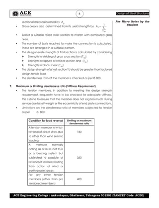
16 Design of Steel Structures
For Micro Notes by the
Student
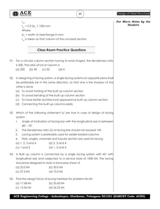
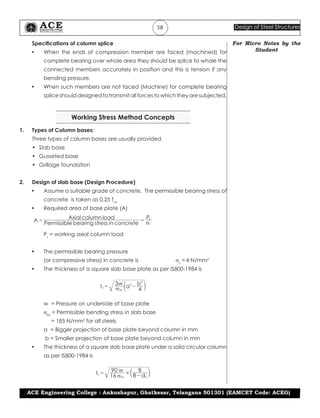
Previous TSPSC & APPSC Questions
01. Net effective area in tension in case of single angle connected by one leg
only is given by: a + kb. The value of k is
(a) 1/ [1+(b/3a)] (b) 1/[1+(a/3b)]
(c) 1/[1+(0.2 b/a] (d) 1/[1+(0.1 b/a)]
02. The maximum permissible slenderness ratio for tension member is
(a) 400 (b) 350 (c) 300 (d) 250
03. The net effective area in case of a single- angle member having the net
connected leg area of 50 mm2
and gross area of unconnected leg as 100
mm2
is
(a) 75 mm2
(b) 130 mm2
(c) 150 mm2
(d) 110 mm2
04. The effective area of 100 ×100 × 6 connected to a gusset plate through one
leg with 20 mm diameter rivets is
(a) 1044.0 mm2
(b) 936.7 mm2
(c) 885.3 mm2
(d) 116.0 mm2
05. Two tension members having different sizes are connected using
(a) Gusset plate (b) Filler plates
(c) Shear legs (d) All of the above
06. The Lug angle is a member which ___ (TSPSC AEE Manager 2015)
(a) is connected to the main tension member to increase its stiffness
(b) is connected to the main tension member for erection purpose.
(c) is connected to the main tension member to increase its strength
locally.
(d) is connected to the main tension member to transfer the tensile force
economically to the joint.
07. Which one is not a possible mode of failure in case of tension members?
(APGENCO Trainee AE-2017)
(a) Yielding of gross section (b) Rupture at the net section
(c) Instability of the element (d) Block shear
KEY for Previous Questions
01. (a) 02. (a) 03. (d) 04. (c) 05. (b)
06. (d) 07. (a)](https://image.slidesharecdn.com/iii-design-of-steel-structures-unit-2-210523063202/85/Iii-design-of-steel-structures-unit-2-16-320.jpg)


![AACE Engineering College : Ankushapur, Ghatkesar, Telangana 501301 (EAMCET Code: ACEG)
36 Design of Steel Structures
For Micro Notes by the
Student
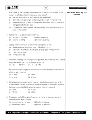
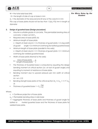
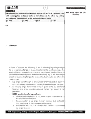
(LSD Principle)
V = 2.5% of axial column load (WSM Principle)
• The lacing should be designed to resist additional shear due to
bending if the compression member carries bending
• For single lacing, the force (Design compression or Design tensile)
in each lacing bar,
;
sin
F
N
V
θ
=
sin
F
V
2 θ
= [for double lacing, (N=2)]
sin
F
V
4 θ
= [for double lacing, (N = 4)]
• The effective slenderness ratio of laced builtup column should be
increased by 5% (IS800:2007 specification only)
Example: 6.6
A built up column consists of two ISMC 450 channels placed back to back
carries factored load of 2500 kN, the single lacing provided with an angle 45o
with longitudinal axis should be designed to transverse shear as per IS800:2007
of
(a) 15.0 kN (b) 22.5kN
(c) 62.5kN (d) 44.1 kN
.Sol:](https://image.slidesharecdn.com/iii-design-of-steel-structures-unit-2-210523063202/85/Iii-design-of-steel-structures-unit-2-36-320.jpg)
![AACE Engineering College : Ankushapur, Ghatkesar, Telangana 501301 (EAMCET Code: ACEG)
38 Design of Steel Structures
For Micro Notes by the
Student
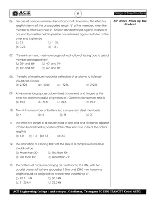
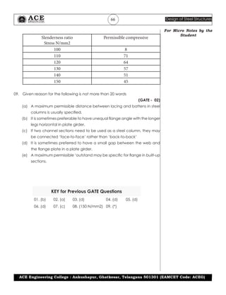
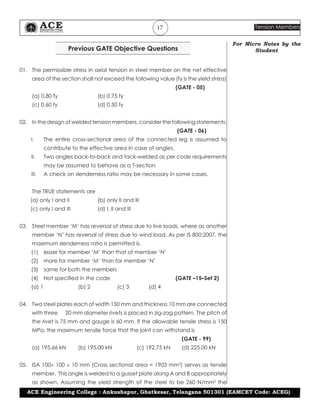
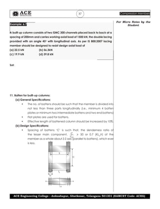
Where,
rc
min
= minimum radius of gyration of component.
S = transverse distance between centroids of bolt group or rivet group
C = Spacing of battens
lb
= transverse distance between centroids of inner end bolt group or rivet
group
• Battens should be designed to carry bending moment and shear
forces arising from a transverse shear of
V = 2.5% of design axial column load
(LSD Principle)
V = 2.5% of axial column load (WSM Principle)
Longitudinal shear on batten, V1
= VC/NS
Moment on batten, M=VC/2N
Where,
N = No. of parallel plates of battens
= 2 in the above figures.
• Thickness of batten, tb 50
b
,
$
lb
= length of batten plate
• Effective depth of batten
d > 3a/4 for intermediate batten
d > a for end batten
d > 2b for any batten
• Over all depth of batten (D)
D = Effective depth of batten (d) + 2x
edge distance
Working Stress Method Concepts
12. Axial compressive strength (Pc
) of a member:
Pc
= Ae
× σac
Where
Ae
= Effective sectional area of a member,
σac
= Axial allowable compressive stress
IS800:1894 uses Merchant Rankine formula to calculate σac
:
.
.
f f
f f
f
0 6
0 6
/
ac
y
n
cc
n n
y cc
y
1
# #
#
σ =
+
7 A
Where,
fy
= Yield stress of steel
fcc
= Elastic critical stress in compression
= π2
E / [KL/r]2
E = Young’s modulus of steel](https://image.slidesharecdn.com/iii-design-of-steel-structures-unit-2-210523063202/85/Iii-design-of-steel-structures-unit-2-38-320.jpg)
![AACE Engineering College : Ankushapur, Ghatkesar, Telangana 501301 (EAMCET Code: ACEG)
39 Compression Members
For Micro Notes by the
Student
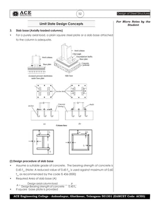
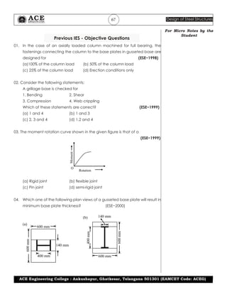
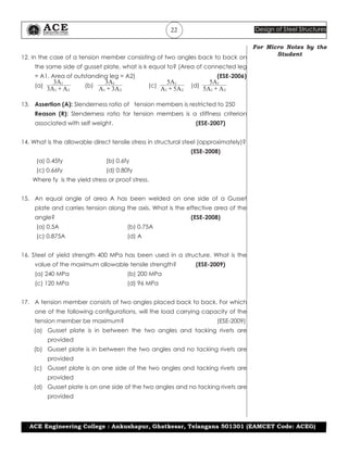
KL/r = Slenderness ratio
Minimum radius of gyration of member
Effective length of member
r
KL
min
=
n = a material factor (n = 1.4 for steel)
Minimum radius of gyration about minor axis
/ /
r I A Minimummoment of inertia Area
min
= =
] g
13. Effective length (KL) and allowable axial compressive stress For angle struts,
the specifications as per IS800:1984 are as follows:
End Condition
Effective
length (KL)
Allowable
axial
compressive
stress (σac
)
(a) For discontinuous members
For single rivet
or bolt
1.0 L 0.8σac
For double
rivet Double
bolt & weld
0.85L σac
(b) For Continuous members
For single or
double angle
0.70L
to
0.85L
σac
14. Cased Columns:
• It is necessary to encase the members of steel framed building in
concrete to meet architectural appearance and also increase fire
resistance and check corrosion of steel members
• For designing of cased column, the entire load is assumed to be taken
steel section only and encasement is taken increasing the stiffness of
the column
Specifications of encased columns:
• The member is of symmetrical I-shape or a single I beam, or channels
back to back with or without flange plates.
• The overall dimensions of the steel section do not exceed 750 mm x
450 mm, the large dimension being parallel to web.
• The load carrying capacity of encased column should not exceed 2
times the load permitted on an uncased column.
• The minimum width of solid casing is bo
+ 100 mm, where bo
is the width
of steel flange of column in mm.
• The radius of gyration for encased column (about YY-axis) is given by](https://image.slidesharecdn.com/iii-design-of-steel-structures-unit-2-210523063202/85/Iii-design-of-steel-structures-unit-2-39-320.jpg)