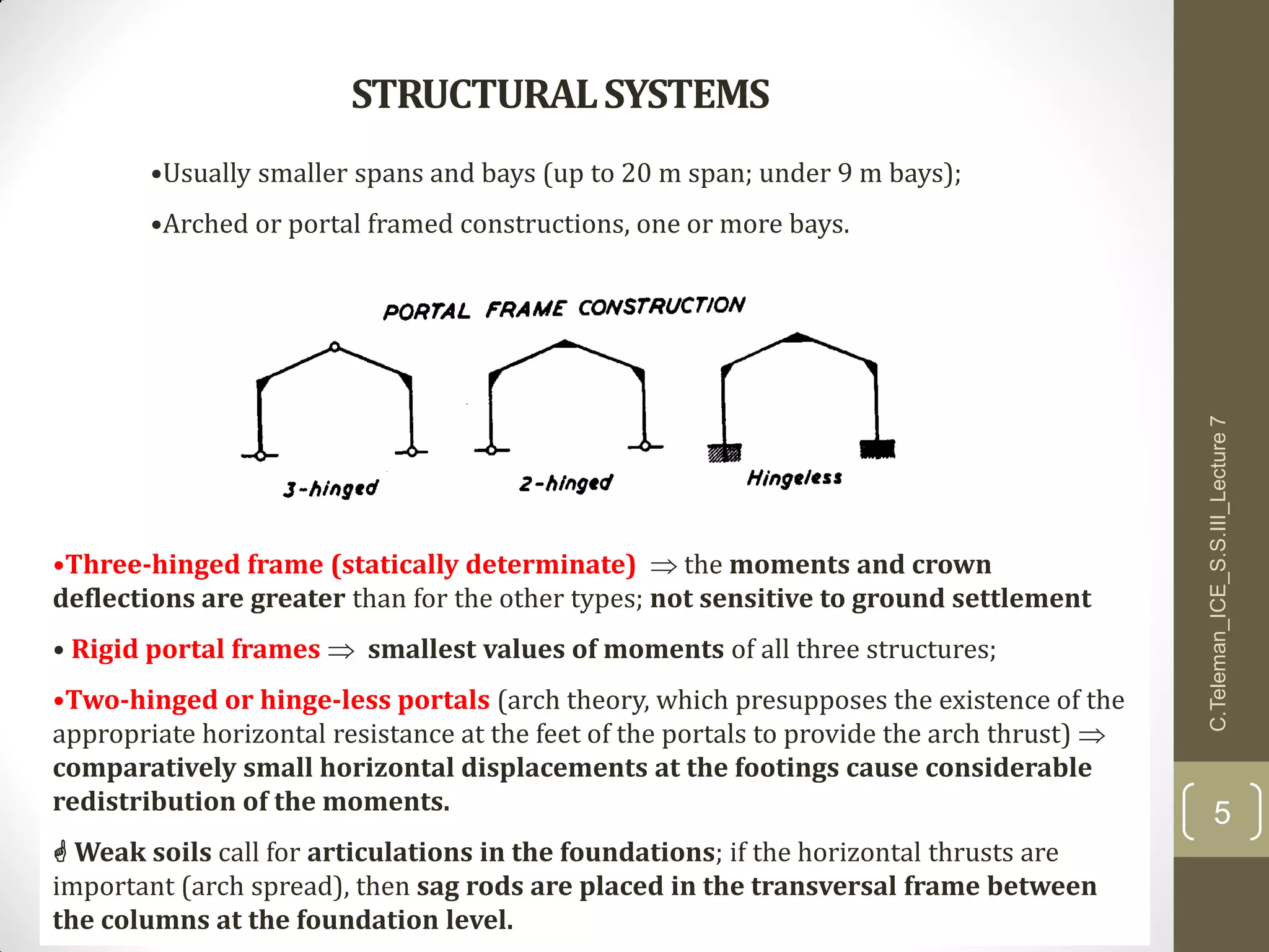
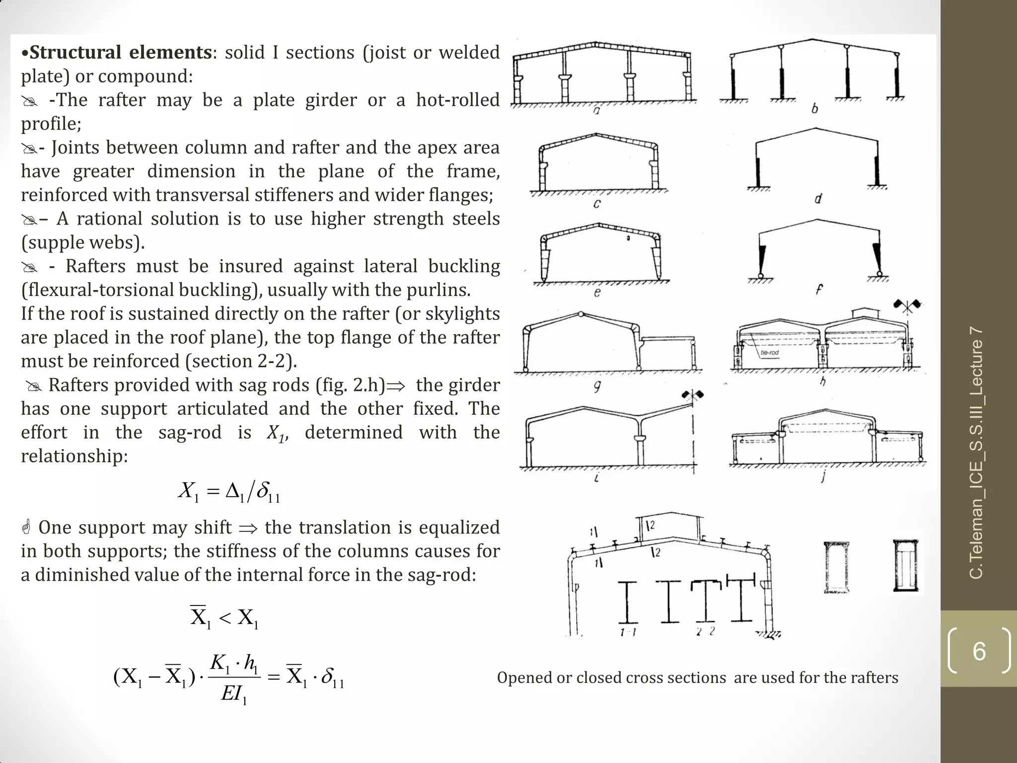
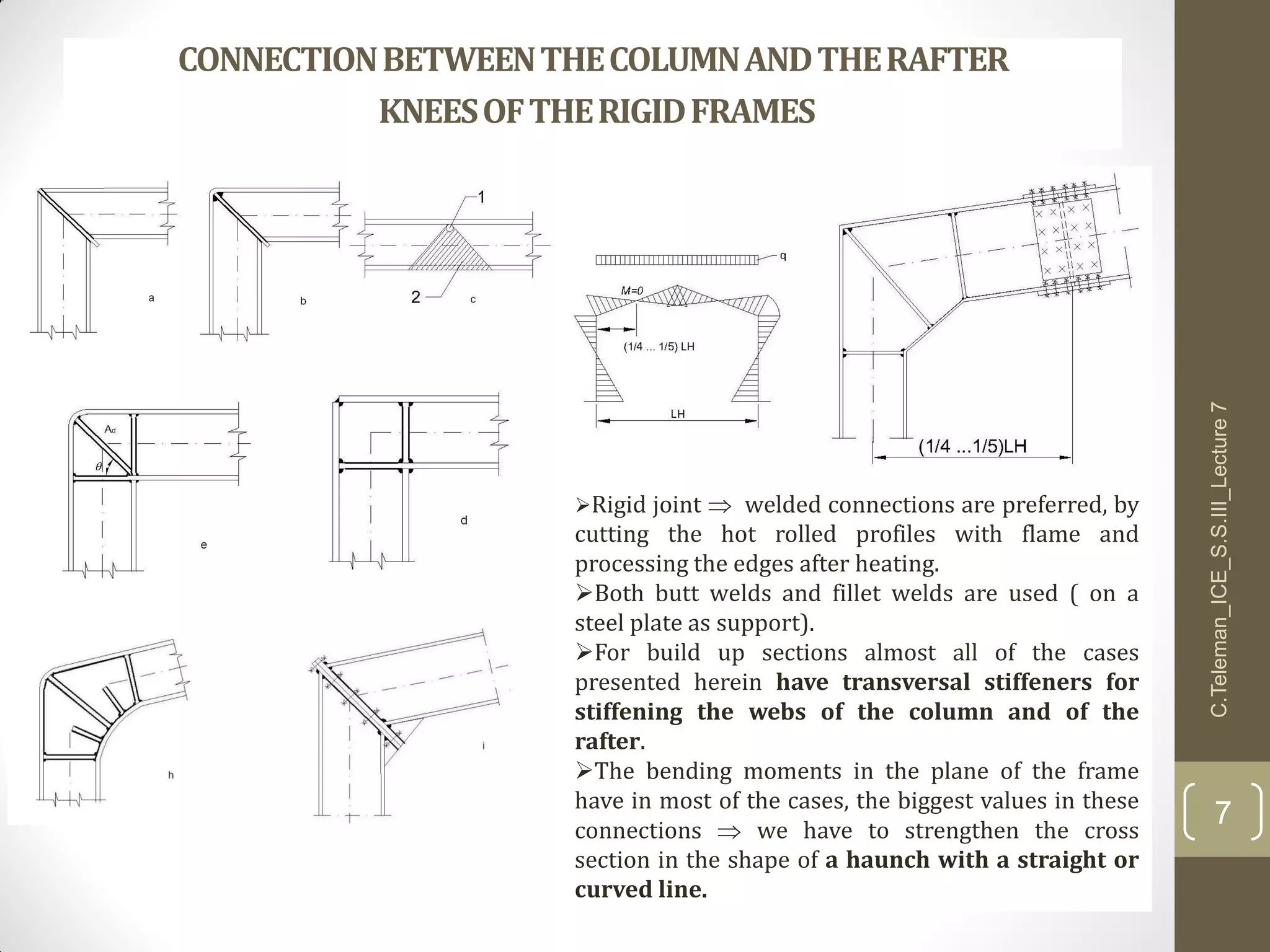
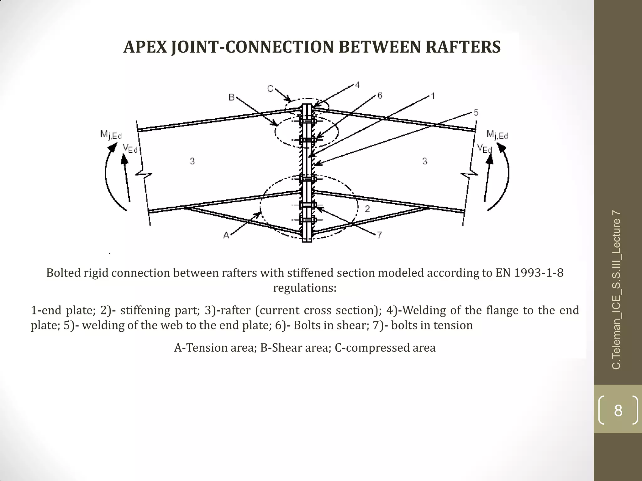
Download as PDF, PPTX
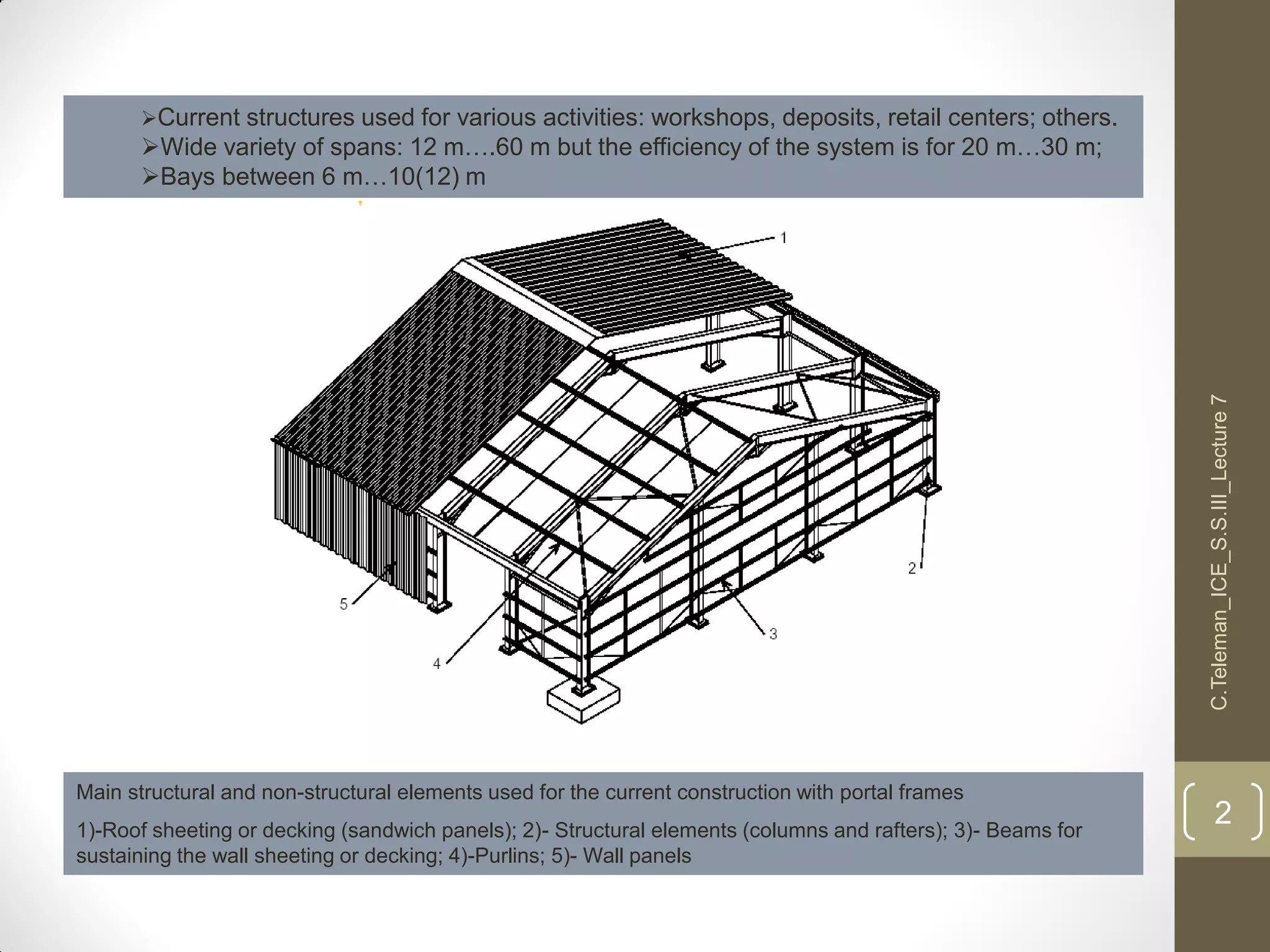
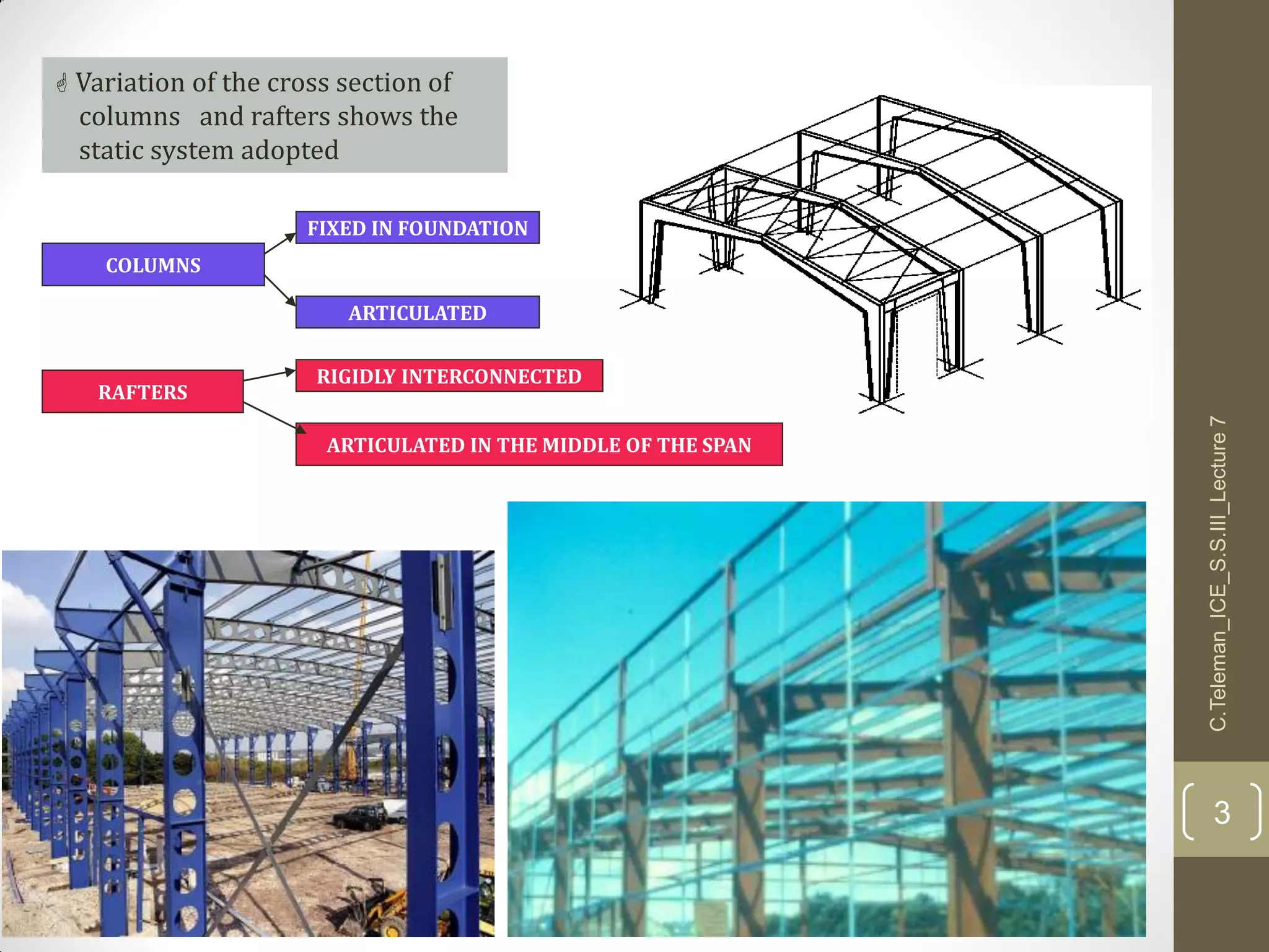
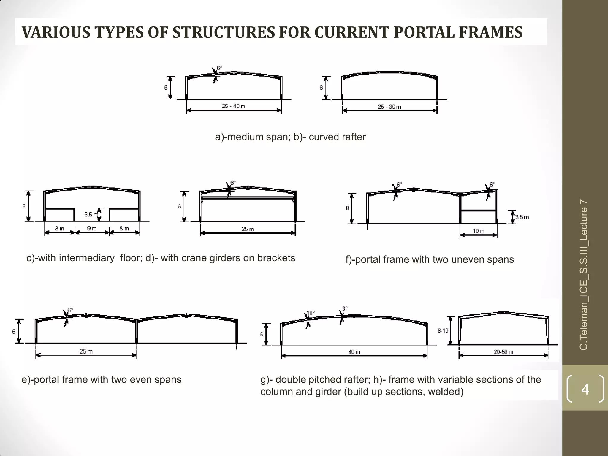
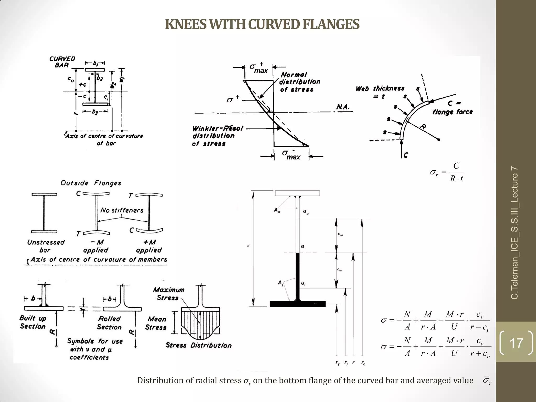
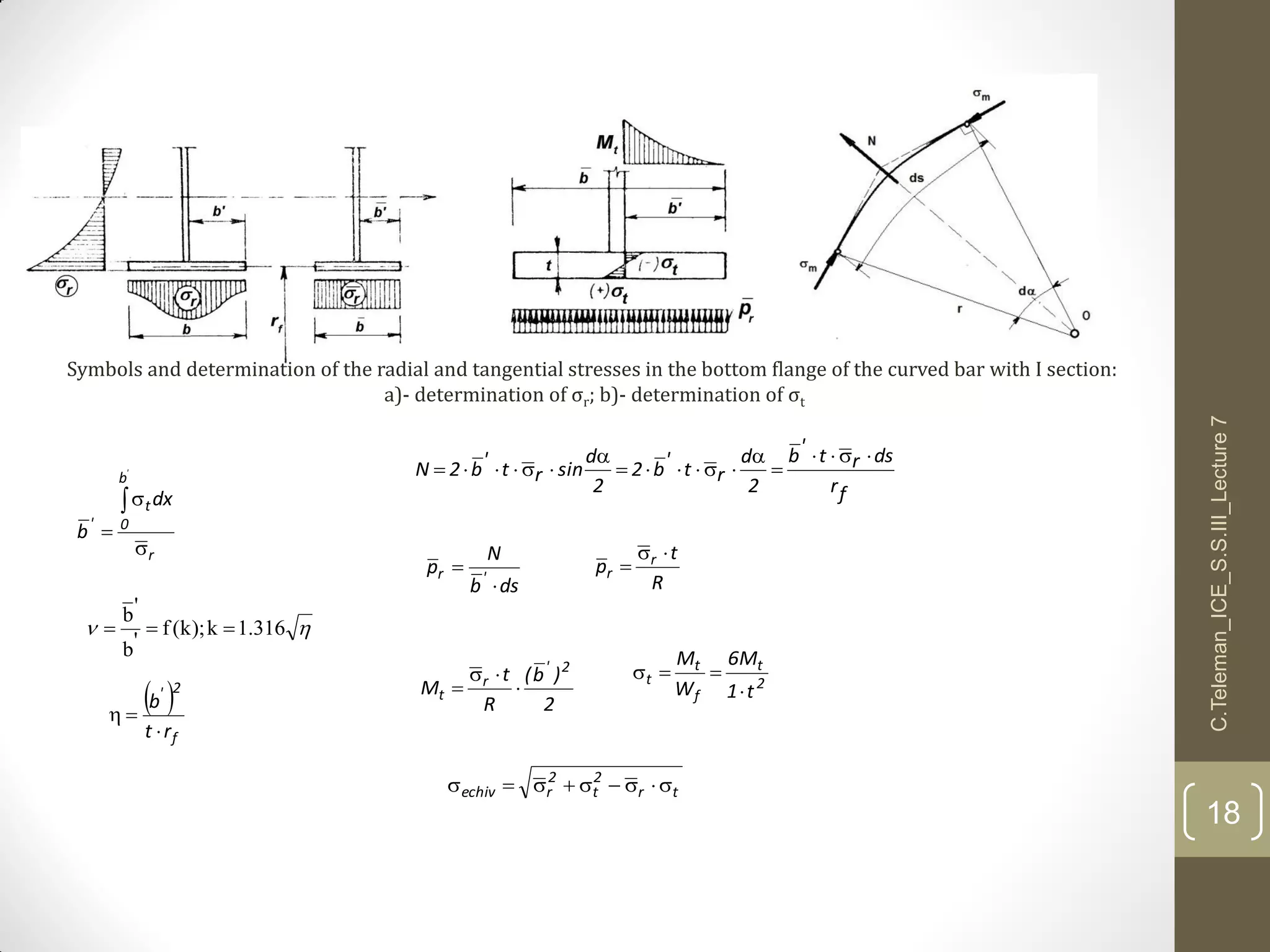
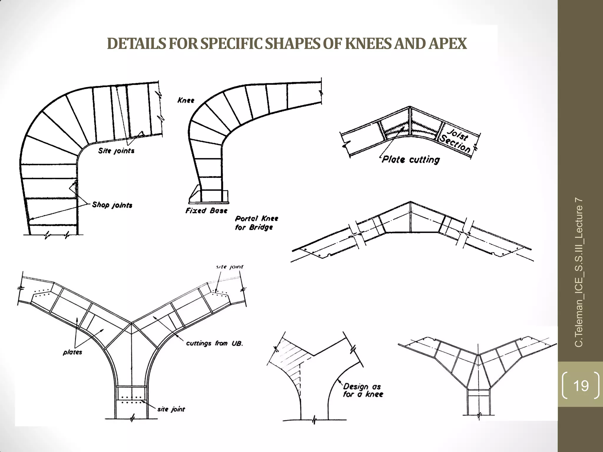
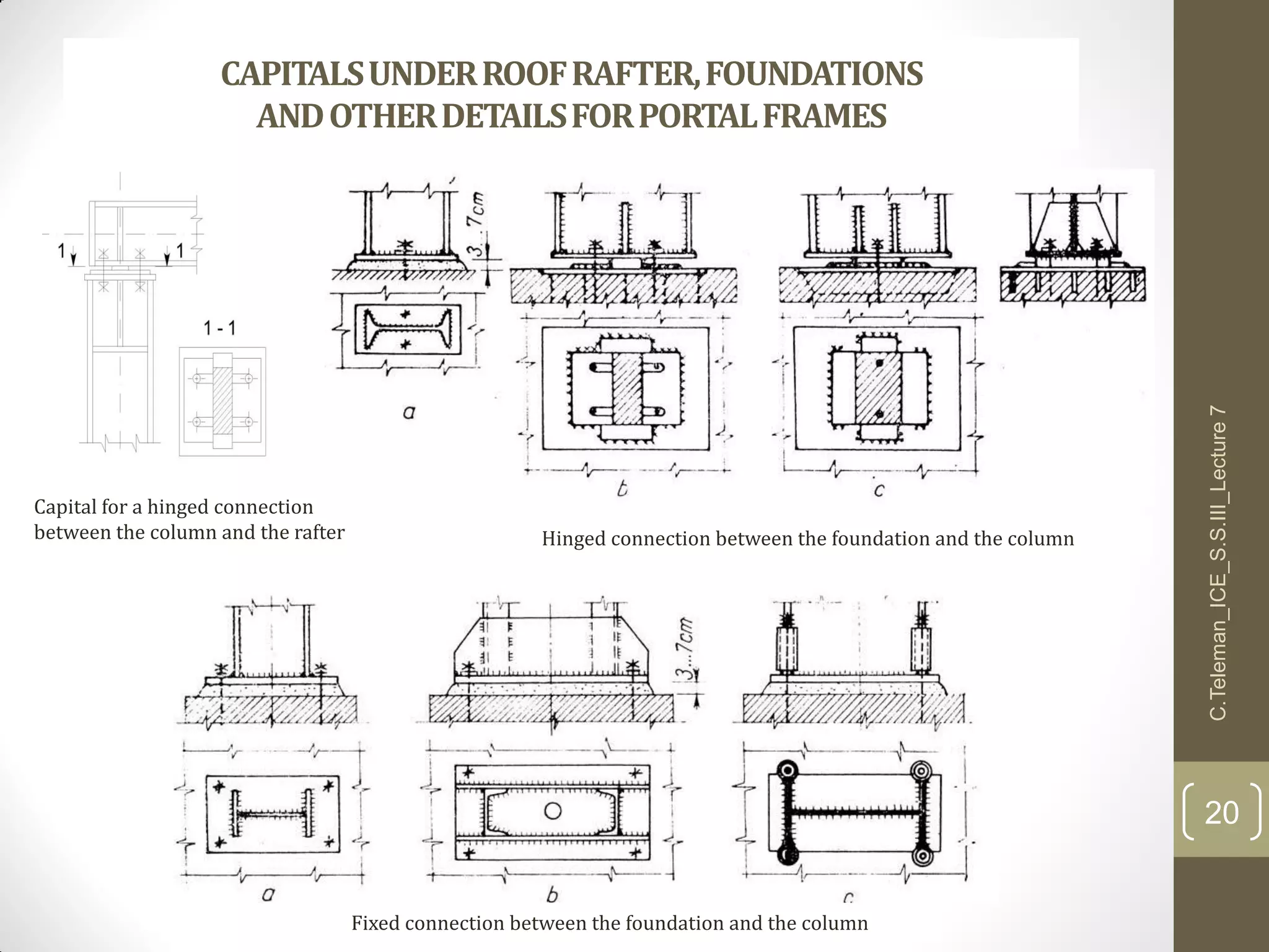
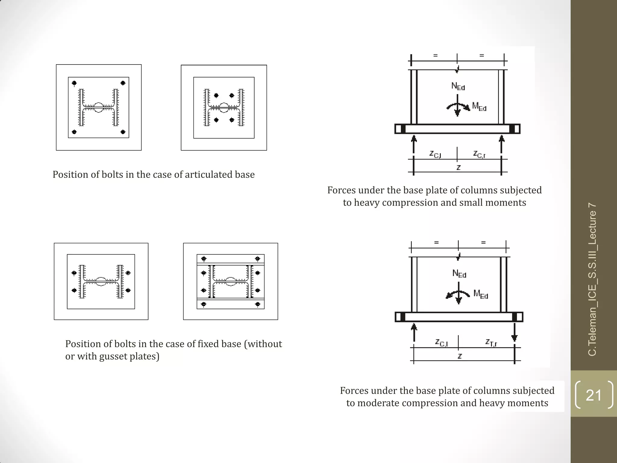
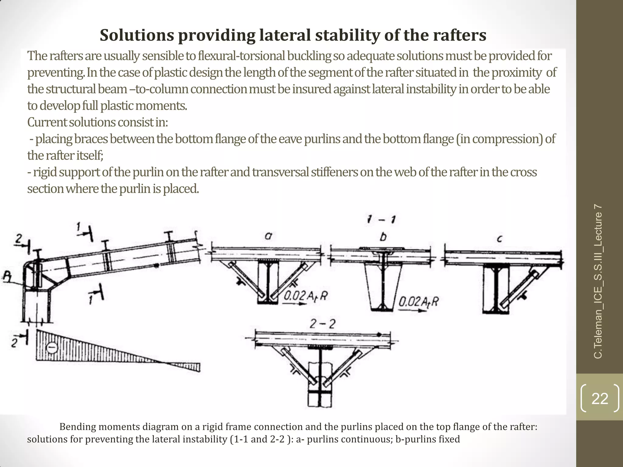

This document discusses portal frame structures used for industrial buildings. It describes the main structural elements including roof sheeting, columns, rafters, beams, and wall panels. Typical spans for portal frames range from 12 to 60 meters, though 20-30 meters is most efficient. Various structural systems and joint connections are examined, including different types of column-rafter joints, apex joints, and design considerations for analyzing and strengthening these critical connections to transfer forces between members. Equations are provided for analyzing stresses in the joints.


![Design of Main Girder [Compatibility Mode].pdf](https://cdn.slidesharecdn.com/ss_thumbnails/designofmaingirdercompatibilitymode-230202104203-b4b70176-thumbnail.jpg?width=640&height=640&fit=bounds)


