Downloaded 405 times
![- 3 -
3.The Load Standard Calculated Value of Each Part
Roof Loading:
Dead Loading Standard Values : 0.67×6=4.02KN/m
Live Loading Standard Value : 0.50×6=3.00KN/m
Column Loading :
Dead Loading Standard Value : 0.5×6×6+4.02×9=54.18KN
Live Loading Standard Value : 3.00×9=27.00KN
Wind Loading Standard Value :
Windward : Column qw1=0.47×6×0.25=0.71KN/m
Rafter qw2=-0.47×6×1.0=-2.82KN/m
Leeward : Column qw3=-0.47×6×0.55=-1.55KN/m
Rafter qw4=-0.47×6×0.65=-1.83KN/m
4. Inner Force Analysis
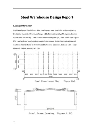
(1)Under Dead Loading
λ=l/h=18/6=3
ψ=f/h=0.9/6=0.15
k=h/s=6/9.0449=0.6634
μ=3+k+ψ(3+ψ)=3+0.6634+0.15×(3+0.15)=4.1359
5289.0
1359.44
15.058
4
58
HA=HE=qlλΦ/8=4.02×18×3×0.5289/8=14.35KN
MC=ql2
[1-(1+ψ) Φ]/8=4.02x182
[1-(1+0.15)×0.5289]=63.78KN·m
MB=MD=-ql2
Φ/8=-4.02×182
×0.5289/8=-86.11KN·m
Inner Force of Steel Frame under dead loading as below figure](https://image.slidesharecdn.com/steelwarehousebuildingdesignreport-170929035417/85/Steel-warehouse-design-report-3-320.jpg)

![- 5 -
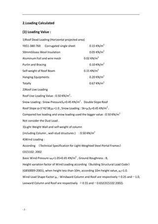
(2) Under Live Loading
VA=VE=27.00KN
HA=HE=3.00×18×3×0.5289/8=10.71KN
MC=3.00×182
[1-(1+0.15)×0.5289]/8=47.60KN·m
MB=MD=-3.00×182
×0.5289/8=-64.26KN·m
Inner Force of Steel Frame under live loading as below figure](https://image.slidesharecdn.com/steelwarehousebuildingdesignreport-170929035417/85/Steel-warehouse-design-report-5-320.jpg)
![- 6 -
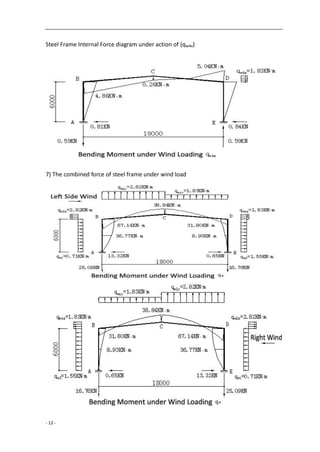
(3) Under Wind Loading
The wind load acting on the roof can be decomposed into the component force qx in the
horizontal direction and the vertical component force qy. Calculated separately, and then
superimposed.
1) The Rafter under the action of wind loading vertical component of forces (qw2y) on
windward side
1322.0)15.058(
1359.416
1
)58(
16
1
KN
l
qa
VE 35.6
182
982.2
2
22
VA=2.82×9-6.35=19.03KN
HA=HE=qlλ Φ /4=2.82×18×3×0.1322/4=5.03KN
MB=MD=5.03×6=30.18KN·m
MC= ql2
[α 2
-(1+ψ ) Φ ]/4=2.82×182
×[0.52
-1.15×0.1322]/4=22.38KN·m](https://image.slidesharecdn.com/steelwarehousebuildingdesignreport-170929035417/85/Steel-warehouse-design-report-6-320.jpg)
![- 7 -
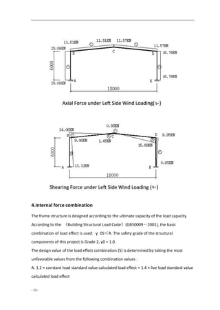
Steel Frame Internal Force diagram under action of (qw2y)
2) The Rafter under the action of wind loading vertical component of forces (qw2y) on
leeward side
KN
l
qa
VE 12.4
182
983.1
2
22
VA=1.83×9-4.12=12.35KN
HA=HE=qlλ Φ /4=1.83×18×3×0.1322/4=3.27KN
MB=MD=3.27×6=19.62KN·m
MC= ql2
[α 2
-(1+ψ ) Φ ]/4=1.83×182
×[0.52
-1.15×0.1322]/4=14.52KN·m
Steel Frame Internal Force diagram under action of (qw2y)](https://image.slidesharecdn.com/steelwarehousebuildingdesignreport-170929035417/85/Steel-warehouse-design-report-7-320.jpg)
![- 8 -
3) The Column under wind loading action qw1 on windward side
α=1,
9803.0]16634.0)6634.015.02(6[
1359.44
1
])2(6[
4
1 22
KK
VA=-VB=-qh1
2
/2L=-0.71×62
/(2×18)=-0.71KN
KN
qh
HA 22.3)9803.0
2
1
2(
2
1671.0
)
2
2(
2
HE=0.71×6-3.22=1.04KN
MD=1.04×6=6.24KN·m
mKN
qh
MC
81.0)]9803.0)15.01(1[
4
1671.0
])1(1[
4
2222
Steel Frame Internal Force diagram under action of (qw1)
mKN
qh
MB
52.6)9803.02(
4
1671.0
)2(
4
2222
](https://image.slidesharecdn.com/steelwarehousebuildingdesignreport-170929035417/85/Steel-warehouse-design-report-8-320.jpg)
![- 9 -
4) The Column under wind loading action qw3 on windward side
VA=-VB=-qh1
2
/2L=-1.55×62
/(2×18)=-1.55KN
KN
qh
HE 02.7)9803.0
2
1
2(
2
1655.1
)
2
2(
2
HA=1.55×6-7.02=2.28KN
MD=7.02×6-1.55×62
/2=14.22KN·m
MB=2.28×6=13.68KN·m
mKN
qh
MC
78.1)]9803.0)15.01(1[
4
1655.1
])1(1[
4
2222
Steel Frame Internal Force diagram under action of (qw3)](https://image.slidesharecdn.com/steelwarehousebuildingdesignreport-170929035417/85/Steel-warehouse-design-report-9-320.jpg)
![- 10 -
5) The Beam under wind loading action (qw2x )on windward side
α=1,β=0
0202.0)15.0134(
1359.48
15.0
KNVV EA 91.0)9.062(
182
9.082.2
HA=2.82×0.9(1+0.0202)/2=1.29KN
HE=2.82×0.9-1.29=1.25KN
mKNMC
39.0]0202.015.15.015.0[
2
69.082.2
MB=1.29×6=7.74KN·m
MD=1.25×6=7.50KN·m](https://image.slidesharecdn.com/steelwarehousebuildingdesignreport-170929035417/85/Steel-warehouse-design-report-10-320.jpg)
![- 11 -
Steel Frame Internal Force diagram under action of (qw2x)
6) The Rafter under the action of wind loading vertical component of forces (qw4x) on
leeward side
KNVV EA 59.0)9.062(
182
9.083.1
HA=1.83×0.9(1+0.0202)/2=0.84KN
HE=1.83×0.9-0.84=0.81KN
mKNMC
26.0]0202.015.15.015.0[
2
69.083.1
MB=0.81×6=4.86KN·m
MD=0.84×6=5.04KN·m](https://image.slidesharecdn.com/steelwarehousebuildingdesignreport-170929035417/85/Steel-warehouse-design-report-11-320.jpg)
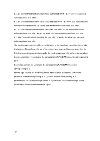

![- 18 -
)
8210
39890
215)(21912200
219
219
12200(
2
=220.90KN·m>M=193.30KN·m,M=Mf
10)1
5.0
( 2
feu
f
u MM
MM
V
V
, OK
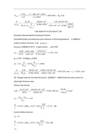
(3) Overall stability checking
N=39.89KN,M=193.30KN·m
A.In-plane Beam Overall stability checking
Calculated Length according beam length : lx=18090mm,
λ x=lx/ix=18090/185.3=97.63<[λ ]=150,b type section ,ψ x=0.570
KN
EA
N e
EX 0.1592
63.971.1
821010206
1.1 2
32
2
0
2
'
0
,β mx=1.0
)
1592
89.39
570.01(101252
1030.1930.1
8210570.0
39890
)1( 3
6
'
0
1
0
EX
xe
xmx
ex
N
N
W
M
A
N
=165.15N/mm2
<f=215 N/mm2
, Ok
B.Out-plane Beam Overall stability checking
Calculated length according two purlin distance or flange bracing distance ,ly=3015mm。
As for uniform section γ =0,μ s=μ w=1
λ y=μ sl/iy0=3015/44.2=68.2,b type section , ψ y=0.762
6.0133.1)
4264.4
122.68
(
101252
4268210
2.68
4320 2
32
by
ψ b’=1.07-0.282/ψ by=0.821
975.0)
N
N
(75.0
N
N
-1.0 2
'
EX0
'
EX0
t
22
3
6
10
/215/73.189
101252821.0
1030.193975.0
8210762.0
39890
mmNfmmN
W
M
A
N
bre
t
ey
(4)《Design Code for Steel Structure》(GB50017-2003) Check the beam web to allow high
thickness ratio.
Beam end section:](https://image.slidesharecdn.com/steelwarehousebuildingdesignreport-170929035417/85/Steel-warehouse-design-report-18-320.jpg)
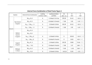
![- 20 -
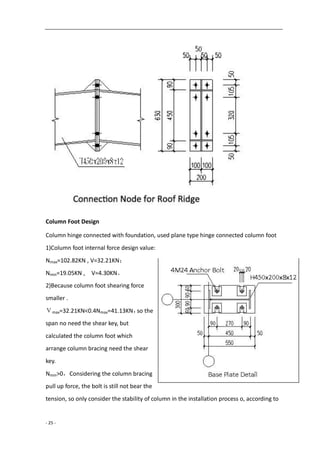
(3)Checking and calculated Column
Shearing Check
Max Shearing for column Vmax=32.21KN
Consider only with supported stiffening rib
8.0562.0235/
34.541
/0
y
w
s f
th
fv=125N/mm2
Vu=hwtwfv=426×8×125=426000N=426.0KN
Vmax=32.21KN<Vu , OK
(2) Bending moment, Shearing force, Pressure action checking together
Checking and calculated the end of beam
N=81.22KN,V=32.21KN,M=193.30KN·N
Because V<0.5Vu , V=0.5Vu, According to code GB70017
))(( 22
2
2
1
1
A
N
fhA
h
h
AM fff
)
8210
81220
215)(21912200
219
219
12200(
2
=215.61KN·m>M=193.30KN·m,M=Mf
10)1
5.0
( 2
feu
f
u MM
MM
V
V
, OK
(3) Overall stability checking
Max Internal Force of steel structure : N=102.82KN,M=193.30KN·m
In-plane Steel Frame Overall stability checking
Height of Column H=6000mm,Length of Rafter L=18090mm.
linear rigidity of column K1=Ic1/h=28181×104
/6000=46968.3mm3
linear rigidity of beam K2=Ib0/(2ψS)=28181×104
/(2×9045)=15578.2mm3
K2/K1=0.332, The calculation length coefficient of the column μ=2.934
Calculated Length of Column lx=μh=17604mm
λx=lx/ix=17604/185.3=95。0<[λ]=150,b type section , ψx=0.588](https://image.slidesharecdn.com/steelwarehousebuildingdesignreport-170929035417/85/Steel-warehouse-design-report-20-320.jpg)
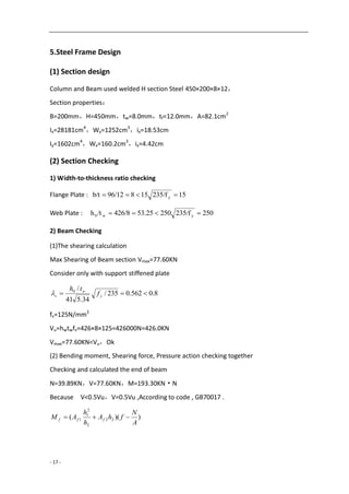
![- 22 -
4.Check the lateral movement of the frame under wind load , μ
Ic=Ib=28181cm4
,ζt= Ic l/hIb=18000/6000=3.0
The equivalent horizontal force of the column is calculated by the following formula :
H=0.67W=0.67×13.56=9.09KN
W=(ω1+ω4)·h=(0.71+1.55)×6.0=13.56KN
mmhmm
EI
Hh
t
c
40150/][1.14)32(
10281811020612
60001009.9
)2(
12 43
333
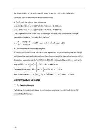
6.Detail Checking
(1) Column and Beam Connected node
1) Bolt Strength Checking
Column and beam node used 10.9Gr , connected by M22 frictional high-strength bolts,
The contact surface of the component is sandblasted, Friction surface anti-slip coefficient
μ = 0.45, each high-strength bolts of the pre-tension of 190KN, the transmission of
internal force design value: N = 39.89KN, V = 77.60KN , M=193.30KN·m
The tension of each bolt :
KNKN
n
N
y
My
N
i
1521908.065.128
8
89.39
)16.0265.0(4
265.030.193
222
1
1
KNKN
n
N
y
My
N
i
1521908.070.75
8
89.39
)16.0265.0(4
16.030.193
222
2
2
Shear force of Bolt Group :
KNVKNpnN f
b
V 60.776.615819045.019.09.0 , OK
Outside row bolt of shear, tension force :
197.0
152
65.128
8/6.615
8/60.77
b
t
t
b
V
V
N
N
N
N
,OK
2)End Plate thickness Checking
End Plate thickness : t=21mm。
Calculated according double side support end plate :](https://image.slidesharecdn.com/steelwarehousebuildingdesignreport-170929035417/85/Steel-warehouse-design-report-22-320.jpg)
![- 23 -
mm
feeebe
Nee
t
wffw
twf
9.20
205)]4640(40220046[
1065.12846406
)](2[
6 3
(3) Calculation of shear stress of beam , column joints
22
6
/125/52.106
10426426
1030.193
mmNfmmN
tdd
M
v
ccb
, OK
(4)Web Plate strength calculated on bolt area
Nt2=75.70KN<0.4P=0.4×190=76.0KN
22
3
/215/52.206
846
101904.04.0
mmNfmmN
te
P
ww
,OK
(2)Mid-span Beam Node
1)Bolt Strength Checking
Mid-span beam node used 10.9Gr , connected by M20 frictional high-strength bolts, The
contact surface of the component is sandblasted, Friction surface anti-slip coefficient
μ = 0.45, each high-strength bolts of the pre-tension of 155KN, the transmission of
internal force design value: N=31.81KN,V=3.21KN,M=143.18KN·m](https://image.slidesharecdn.com/steelwarehousebuildingdesignreport-170929035417/85/Steel-warehouse-design-report-23-320.jpg)
![- 24 -
The tension of each bolt :
KNKN
n
N
y
My
N
i
1241558.001.95
8
81.31
)16.0265.0(4
265.018.143
222
1
1
KNKN
n
N
y
My
N
i
1241558.079.55
8
81.31
)16.0265.0(4
16.018.143
222
2
2
Shear force of Bolt Group :
KNVKNpnN f
b
V 21.32.502815545.019.09.0 , OK
Outside row bolt of shear, tension force :
177.0
124
01.95
8/2.502
8/21.3
b
t
t
b
V
V
N
N
N
N
, OK
2)End Plate thickness checking
End Plate thickness t=18mm
Calculated according double side support end plate :
mm
feeebe
Nee
t
wffw
twf
8.17
205)]4640(40220046[
1001.9546406
)](2[
6 3
3) Web Plate strength calculated on bolt area
Nt2=55.79KN<0.4P=0.4×155=62.0KN
22
3
/215/48.168
846
101554.04.0
mmNfmmN
te
P
ww
, OK](https://image.slidesharecdn.com/steelwarehousebuildingdesignreport-170929035417/85/Steel-warehouse-design-report-24-320.jpg)
![- 27 -
KNN
fAf
N
y
16.121009.12
68.44cos60
21512200
235cos60
3
Connected bolt used normal C grade M12
Bolt , The calculation length of the corner
supports the distance between the two ends
of the bolt center : l0=633mm , used L50x4 ,
section properties:
A=3.90cm2
,Iu=14.69cm4
,Wu=4.16cm3
,
iu=1.94cm,iv=0.99cm
λ u=l0/ iu=633/19.4=32.6<[λ ]=200,
b type section , ψu=0.927
Strength design value that single side
connected angle multiplied with the
reduction factor , αy:λ=633/9.9=63.94,
αy=0.6+0.0015λ=0.696
22
3
/215/0.48
390927.0696.0
1016.12
mmNfmmN
A
N
uy
, OK
(2) Purlin Design
Basic Information
Purlin used Galvanized C section steel, design according
single span simple member, roof slope :1/10,purlin
span6m ,set one row sag rod , purlin distance 1.5m ,steel
materials Q235B.
Loading and Internal force
Consider the combination of dead load and roof live load as the control effect ,
Purlin linear load standard value: Pk=(0.27+0.5)×1.5=1.155KN/m
Purlin linear load design value: Pk=(1.2×0.27+1.4×0.5)×1.5=1.536KN/m
Px=Psinα=0.153KN/m,Py=Pcosα=1.528KN/m ;
Design value of bending moment :](https://image.slidesharecdn.com/steelwarehousebuildingdesignreport-170929035417/85/Steel-warehouse-design-report-27-320.jpg)

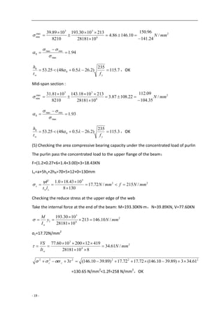
![- 30 -
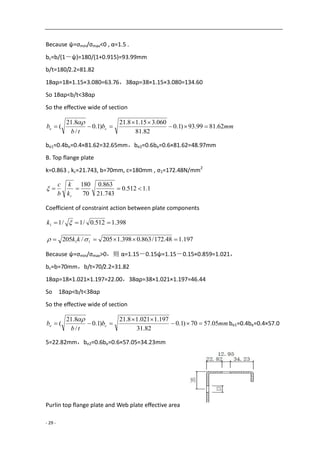
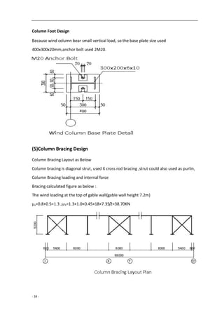
C. Lower Flange Plate
Lower Flange Plate total cross section under tension and effective .
D. Effective net-section modulus
Top Flange deduct area the wide :70-57.05=12.95mmWeb Plate deduct area the wide :
93.99-81.62=12.37mm, and the calculated section of web plate with aφ 13 sag rod hole
(35mm distance from top flange plate), hole position same as the deduct area, so the
deduct area of web plate calculated accordingφ 13.see figure ,the effective net-section
modulus :
34
224
10813.3
90
)3590(2.213902.295.121090.374
mmWenx
1.21
)2/2.21.21(2.213)1.2182.222/95.12(2.295.121097.48 224
max
enyW
34
10257.2 mm
1.2170
)2/2.21.21(2.213)1.2182.222/95.12(2.295.121097.48 224
max
enyW
34
10974.0 mm
Wenx/Wx=0.915,Wenymax/Wymax=0.973,Wenymin/Wymin=0.972
Strength Calculated
Consider roof could stop purlin lateral buckling and torsion:
22
4
6
4
6
max
1 /205/97.187
10257.2
1017.0
10813.3
1088.6
mmNfmmN
We
M
W
M
ny
y
enx
x
22
4
6
4
6
min
2 /205/99.162
10974.0
1017.0
10813.3
1088.6
mmNfmmN
We
M
W
M
ny
y
enx
x
Deflection Calculated
mmlmmy 30200/][11.25
109.37410206
6000"38'425cos155.1
384
5
43
4
,OK](https://image.slidesharecdn.com/steelwarehousebuildingdesignreport-170929035417/85/Steel-warehouse-design-report-30-320.jpg)
![- 31 -
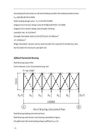
Structural requirement
λx=600/7.06=85.0<[λ]=200 , OK
λy=300/2.55=117.6<[λ]=200 , OK
(3) Wall Girt Design
1)Basic Information
The Building project is single floor workshop, column distance 6m,eave height
6m ,above1.2m is corrugated single color sheet ,wall girt distance 1.5m, one row sag rod,
steel materials Q235B
2)Loading Calculated
Wall Girt used Galvanized C section steel :160x60x20x2.5mm ,wall weight : 0.22KN/m2
Wind Loading
Basic wind loading: ω0=1.05×0.45=0.473KN/m2
, wind loading standard value calculated
according CECS102:2002 ωk=μsμzω0,μs=-1.1(+1.0)
When Calculated the wall girt no need calculated the weight of wall ,the wall sit on ground
qx=1.2×0.07=0.084KN/m,qy=-1.1×0.473×1.5×1.4=-1.093KN/m
3)Internal force calculated
Mx=0.084×62
/8=0.378KN·m , My=1.093×62
/8=4.919KN·m
4)Strength Calculated
Wall Girt :C160×60×20×2.5mm
Wxmax=19.47cm3
,Wmin=8.66cm3
,Wy=36.02cm3
,Iy=288.13cm4
Reference wall purlin calculated result and project experience
Wenx=0.9 Wx , Weny=0.9 Wy
22
3
6
3
6
/205/2.200
1002.369.0
10919.4
1066.89.0
10378.0
mmNfmmN
W
M
W
M
eny
y
enx
x
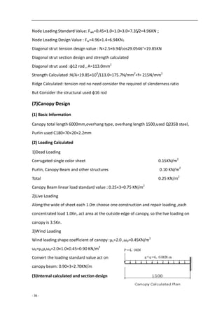
Under wind suction , the sag rod set at the internal of wall girt ,and arrange the inclined
sag rod at the bottom of column ,and corrugated color sheet strong connected with](https://image.slidesharecdn.com/steelwarehousebuildingdesignreport-170929035417/85/Steel-warehouse-design-report-31-320.jpg)
![- 32 -
outside of wall girt ,so don’t need calculated the overall stability of wall girt.
5) Deflection calculated
mmlmm 30200/][3.22
1013.28810206
60005.1473.01.1
384
5
43
4
, OK
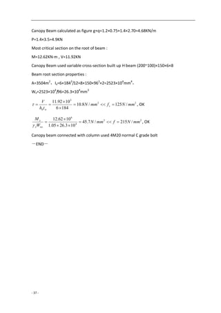
(4) Wind Column Design
Basic information
Wind Column height 6274mm ,distance 6m ,bearing loading including self-weight, wall
girt weight ,and gable wall wind loading ,wind column hinge connected with foundation,
design as compression-bending members. Wind Column used as simple member which
support roof beam and foundation.
Wind Pressure ω0=0.45KN/m2
, Ground roughness category B, Fly Bracing distance
3.0m,Wind Column used Q235B steel .
Loading Calculated
Wind Column used H section steel 300×200×6×10, self-weight:g1=44.6kg/m
Wind Loading calculated according : CECS102:2002
ωk=μsμzω0 ,μs=-1.0(+1.0) ,ω0=1.05×0.45=0.473KN/m2
qz=1.2×(0.07×6×3+44.6×6.274×10-2
)=4.87KN
qy=1.4×1.0×1.0×0.473×6=3.97KN/m
Wind Column eccentricity under wall girt act :1.2×0.07×6×3×0.23=0.35KN·m
Internal Force Calculated
N=4.87KN , M=1/8×3.97×6.2742
+0.35=19.88KN·m
Local Stability Checking of Steel Structure
Width-to-thickness ratio of flange : b/t=96/10=9.6< yf/23513
2
3
63
max
min /
49.30
21.32
101.634
1088.19
56800
1087.4
mmN
W
M
A
N
x
x
947.1
max
minmax
0
,因 1.6<α 0<2.0,
l0=6274mm,λ x= l0/ ix=48.5<[λ ]=150](https://image.slidesharecdn.com/steelwarehousebuildingdesignreport-170929035417/85/Steel-warehouse-design-report-32-320.jpg)
![- 33 -
7.46
6
280
5.91
235
)2.265.048( 0
0
wy t
h
f
, OK
Strength Calculated
Section Properties : A=56.8cm2
,Ix=9511cm4,Wx=634.1cm3
,ix=12.94cm,
Iy=1334cm4
,Wy=133.4cm3
,iy=4.85cm
22
3
63
/215/7.30
101.63405.1
1088.19
56800
1087.4
mmNfmmN
W
M
A
N
nxx
x
n
Checking the In-plane stability under bending moment
λ=48.5 , b type section , ψx=0.863
KN
EA
NEX 1.4463
5.481.1
568010206
1.1 2
32
2
2
'
,βmx=1.0
)
1.4463
87.4
8.01(101.63405.1
1088.190.1
56800863.0
1087.4
)8.01( 3
63
'1
EX
xx
xmx
x
N
N
W
M
A
N
=30.85N/mm2
<f=215 N/mm2
, OK
Checking the Out-plane stability under bending moment
Consider the fly bracing as Lateral Support of Out-plane wind column l0y=3000mm,
λy= l0y/ iy=3000/48.5=61.9<[λ]=150,b type section , ψy=0.797
983.0
23544000
07.1
2
yy
b
f
,η=1.0,βtx=1.0
3
63
1 101.634983.0
1088.190.10.1
56800797.0
1087.4
xb
xtx
y W
M
A
N
=32.97N/mm2
<f=215 N/mm2
OK
Deflection Calculated
Wind Column under the action of horizontal wind loading could see as single
span ,simply-supported beam and calculated horizontal deflection according below:
mmlmm
EI
l
x
k
7.15400/][1.4
10951110206
627497.3
384
5
384
5
43
44
](https://image.slidesharecdn.com/steelwarehousebuildingdesignreport-170929035417/85/Steel-warehouse-design-report-33-320.jpg)

This document describes the design of a single-floor steel warehouse with specifications including an 18m clear span, 6m eave height, and various loading calculations for dead, live, and wind loads based on structural guidelines. It details the materials used, structural configurations, load combinations, and internal force analysis required to ensure safety and compliance with building codes. The document concludes with a consideration of the frame design and section checking for structural integrity.


