Downloaded 124 times
![1 Prepared by Prof. Shehab Mourad – Department of Civil Eng. - KSU
Example 1
Solution:
1- Beam effect (beam strength)
Lb = 9m
For W 310 x 97, f Mp = 358 kN.m, f Mr = 235 kN.m, Lp = 3.83 m, Lr = 13.6 m ,
BF = 12.6
Lr > Lb > Lp beam strength is located in zone 2
Obtain Cb = 1.14 for uniform load on simply supported beam that is laterally
supported at ends only.
f Mn = 1.14 [ 358 – 13.2 (9 – 3.83) ] = 330 kN.m < f Mp
f Mnx = 330 kN.m
2- Beam-Column Effect
The beam is braced at ends,
Maximum moment = Mnt = w L2
/8 = 10 . (9)2
/8 = 101.25 kN.m
B1 = Cm
1 - Pu /Pe1
Cm = 1.0 , for hinged-hinged beam with uniform transverse loads
Pe1 = p2
E I = (3.14)2
(2 x 10⁵
) (222 x 106
) x 10-3
= 5410.00 kN
(KL)2
(9000)2
B1 = 1.0 = 1.15 ³ 1.0 B1 = 1.15
1 – 700/5410
Ultimate maximum moment at mid span = Mux
= B1 x Mnt = 1.15 x 101.25 = 116.44 kN.m
W u = 10 kN/mPu = 700 kN
9 m
Pu = 700 kN
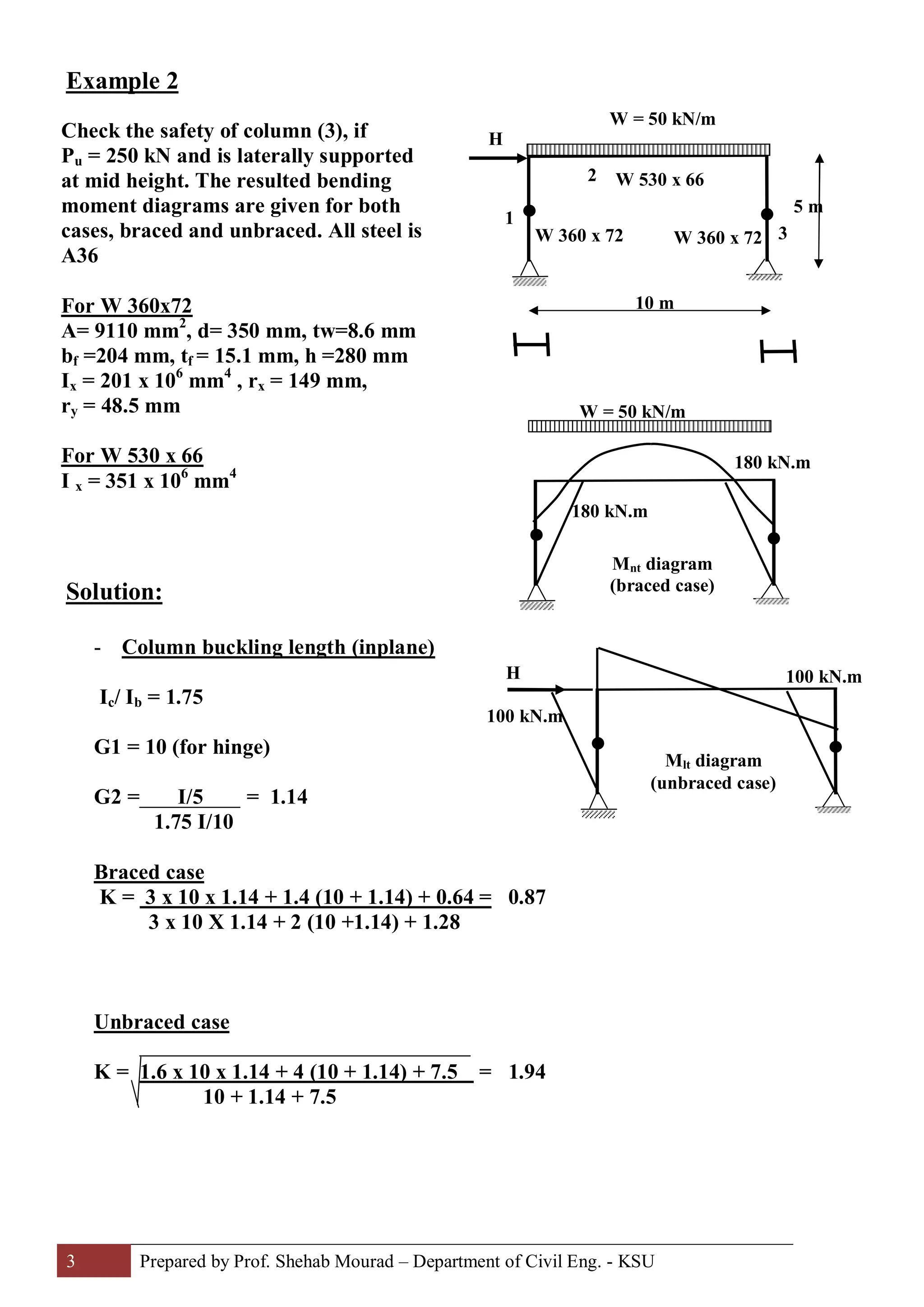
Check the safety of the
shown beam to resist the
given ultimate loads, if the
beam section is W 310 x 97
(A36) and the compression
flange of the beam is only
laterally supported at ends.](https://image.slidesharecdn.com/19examplesforbeam-colum-170818193416/75/19-Examples-for-Beam-Column-Steel-Structural-Design-Prof-Shehab-Mourad-1-2048.jpg)

![4 Prepared by Prof. Shehab Mourad – Department of Civil Eng. - KSU
1- Beam effect
Lb = 5.0 / 2 = 2.5 m
For W 360 x 72; f Mp = 288 kN.m, f Mr = 187 kN.m,
Lp = 2.41 m, Lr = 7.98 m , BF = 18.1
Lr > Lb > Lp beam strength is located at zone 2
Cb = 12.5 M = 1.25
2.5 M + 3 x 0.63 M + 4 x 0.75 M + 3 x 0.88 M
f Mn = 1.25 [ 288 – 18.1 (2.5 – 2.41)] = 357 kN.m > f Mp = 288 kN.m
f Mn = f Mp = 288 kN.m
2 – Beam – Column effect
(braced case)
B1 = Cm
1 - Pu /Pe1
where Cm = 0.6 – 0.4 ( 0 ) = 0.6
180
Pe1 = p2
E I = (3.14)2
(2 x 10⁵
) (201 x 106
) x 10-3
= 20946 kN
(KLx)2
(0.87 x 5000)2
B1 = 0.6 = 0.61 < 1.0
1 – ( 250/20946)
B1 = 1.0
(unbraced case)
B2 = 1 > 1.0
1 - ∑Pu /∑Pe2
∑Pu = 50 x 10 = 500 kN
Pe2 = p2
E I = (3.14)2
(2 x 10⁵
) (201 x 106
) x 10-3
= 4212.5 kN
(KLx)2
(1.94 x 5000)2
B2 = 1 = 1.06
1 – [500 / (2 x 4212.5)]
Mux = B1 Mnt + B2 Mlt = 1 x 180 + 1.06 x 100 = 286.3 kN.m
Lb = 2.5 m
Lb = 2.5 m
0.5 M
0.63 M
0.75 M
0.88 M
M](https://image.slidesharecdn.com/19examplesforbeam-colum-170818193416/75/19-Examples-for-Beam-Column-Steel-Structural-Design-Prof-Shehab-Mourad-4-2048.jpg)


1. The document provides examples of checking the strength of beams and columns. 2. In the first example, the beam section W 310 x 97 is checked to resist ultimate loads and is found to be safe. 3. In the second example, the safety of column section W 360 x 72 is checked for a given load of 250 kN when laterally supported at mid-height. It is found to be unsafe by about 8% and requires a larger section.