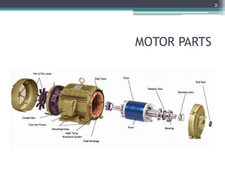
The document discusses the design of the stator in an electric motor. It covers key aspects of stator design including the stator lamination material and patterns, winding methods, insulation techniques, and manufacturing processes. Design considerations like reducing cogging torque, maintaining a small air gap, effective stator cooling, and robust stator construction are also addressed to optimize motor performance and reliability.
The induction motor operates on the principle of electromagnetic induction. It consists of two main parts - the stator and the rotor. The stator contains windings that generate a rotating magnetic field, acting as the primary. This rotating field induces currents in the rotor windings, which acts as the secondary. The rotor is then pushed to rotate at a slightly lower speed than the rotating field due to "slip."
- The document discusses different types of armature windings for DC and AC machines, including lap, wave, simplex, duplex, mush, and double layer windings.
- It describes the characteristics of each winding type such as the connections between coils and how they are arranged in the slots. Key terms related to pitch, spacing, and phase relationships are also defined.
- The final section covers conditions for designing double layer windings for AC machines, distinguishing between integral and fractional slot types.
The document discusses the Geneva mechanism, which converts continuous rotation into intermittent rotary motion. It does this through a drive wheel with a pin that engages slots on a driven wheel, advancing it by one step. There are three main types: external, internal, and spherical. Applications include film projectors, mechanical watches, assembly lines, and CNC machines. The Geneva mechanism provides a simple solution for intermittent motion but exhibits more jerk than more advanced cam systems. Future uses could include engine applications, bottle indexing, and pen changers.
An alternator is an electrical generator that converts mechanical energy to electrical energy. It uses a rotating magnetic field with a stationary armature. The working principle relies on Faraday's law of electromagnetic induction. As the armature rotates within the magnetic field, an alternating current is produced. The main components are the stator with stationary armature windings and the rotor with a rotating magnetic field supplied by a DC current. Armature reaction causes the magnetic field to be distorted by the armature current. Alternators have various applications including in automobiles, power plants, and for providing regenerative braking in induction motors. Induction generators can also be used to convert the rotational energy of windmills into electrical energy.
BLDC motors have evolved from conventional DC motors to permanent magnet DC motors to brushless permanent magnet DC motors. A BLDC motor consists of a stator and a rotor, with the rotor containing permanent magnets and the stator containing coil windings. BLDCs improve reliability and efficiency over brushed DC motors by replacing the brush and commutator assembly with electronic commutation, which controls the sequence of energizing the stator windings. This electronic control allows BLDCs to have higher speed and torque characteristics than conventional DC motors.
The document discusses induction motors, which are asynchronous AC motors that operate below synchronous speed. It describes the two main types - single phase and three phase induction motors. Three phase induction motors are commonly used in industry due to their ability to provide bulk power conversion from electrical to mechanical power. The document then discusses the construction and working principles of three phase induction motors in detail, including their stator, rotor, and how rotational motion is induced in the rotor via electromagnetic induction from the rotating stator magnetic field.
1. Shaft couplings are used to connect shafts that are manufactured separately or to introduce flexibility between shafts. The main types are rigid and flexible couplings.
2. Rigid couplings transmit torque without losses but require perfectly aligned shafts. Flexible couplings allow for misalignment. Common rigid couplings are sleeve, clamp, and flange couplings.
3. Flange couplings use separate cast iron flanges keyed to each shaft end and bolted together. The flanges and bolts are designed to transmit the torque between the shafts. Flexible couplings like bush pin couplings introduce mechanical flexibility.
An alternator is an electrical generator that converts mechanical energy to electrical energy in the form of alternating current. For reasons of cost and simplicity, most alternators use a rotating magnetic field with a stationary armature.
This document discusses different types of gear trains including simple, compound, reverted, and epicyclic gear trains. It provides details on the components, configurations, terminology, and methods for calculating speed and velocity ratios for each type of gear train. Key points covered include how simple gear trains involve one gear on each shaft, compound gear trains have multiple gears on a shaft, reverted gear trains have coaxial input and output shafts, and epicyclic gear trains allow shaft axes to move relative to a fixed axis. Formulas and a tabular method are presented for analyzing epicyclic gear trains.
Three phase Induction Motor (Construction and working Principle)Sharmitha Dhanabalan
The three phase induction motor consists of a stationary stator and a rotating rotor. The stator contains three-phase windings that generate a rotating magnetic field. This rotating field induces currents in the rotor windings, causing the rotor to turn. There are two common types of rotors - squirrel cage and wound rotor. A squirrel cage rotor has embedded conductors inside its core that are permanently short-circuited. A wound rotor has three insulated windings connected to slip rings to allow external resistance control. Due to slight differences in speed, the rotor always rotates at a slightly slower synchronous speed than the stator's magnetic field.
- Stepper motors are brushless DC motors that rotate in discrete steps in response to control signals. They are excellent for positioning applications as their rotation can be accurately controlled.
- There are three main types of stepper motors: permanent magnet, variable reluctance, and hybrid. Permanent magnet motors are the most common.
- Key components include the rotor, stator, and windings. Pulses sent to the windings energize the stator poles and rotate the motor.
- Stepper motors have advantages like low cost control, simplicity, and ability to operate without feedback but disadvantages like higher current draw and need for a driver circuit.
- Common applications include printers, CNC machines, robotics, and
Design of stator & rotor for Wound Induction MotorParth Patel
The document provides details on the design of stator and rotor slots for a 3-phase wound-rotor induction motor. It discusses the construction of the motor including the stator core and winding, wound rotor with slip rings, and end shields. For stator design, it describes slot types, selection of number of slots, conductor cross-section, slot area and size, length of mean turn and resistance calculation. For rotor design, it discusses air gap length, number of rotor slots selection to avoid crawling and cogging, end ring current, design of wound rotor including number of turns and rotor current calculation. It provides an example design problem for a 30kW squirrel cage induction motor and asks to design a suitable rotor
Design factors; Limitations; Modern trends; Electrical
Engineering Materials; Space factor; Choice of Specific
Electric and Magnetic loadings; Thermal Considerations;
Heat flow; Temperature rise; Insulating Materials; Properties;
Rating of Machines; Various Standard Specifications ;
Types of electric motors include DC motors, AC motors, and other specialty motors. DC motors include shunt, series, and permanent magnet motors. AC motors include induction and synchronous motors. Other motors include reluctance, hysteresis, stepper, and brushless DC motors. The document provides details on the operating principles and applications of these various electric motor types.
A reluctance motor is a type of electric motor that induces non-permanent magnetic poles on the ferromagnetic rotor. The rotor does not have any windings. It generates torque through magnetic reluctance.
Reluctance motor sub types include synchronous, variable, switched and variable stepping.
Reluctance motors can deliver high power density at low cost, making them attractive for many applications. Disadvantages include high torque ripple (the difference between maximum and minimum torque during one revolution) when operated at low speed, and noise due to torque ripple.
The document discusses tachogenerators, which are devices that measure the speed of a rotating shaft by converting angular velocity into a voltage. There are two main types: DC tachogenerators, which generate a DC voltage corresponding to speed, and AC tachogenerators, which generate an AC voltage that must be rectified. Both work by inducing an electromotive force in a conductor based on its motion through a magnetic field, per Faraday's law of induction. Tachogenerators are used to measure speeds of electric motors, engines, and powered equipment.
This document discusses various topics related to power screws including:
- Types of screw threads used for power transmission like square, acme, and buttress threads.
- The torque required to raise or lower a load using a square threaded screw, which depends on the helix angle and friction angle.
- The maximum efficiency of a square threaded screw occurs at a helix angle between 40-45 degrees.
- Self-locking screws have a friction angle greater than the helix angle, while overhauling screws have a friction angle less than the helix angle.
- Additional sections cover efficiency as it relates to screw and collar friction, stresses in power screws, differential and compound screws, and design considerations for screw
A pneumatic control valve actuator converts energy (typically in the form of compressed air) into mechanical motion. The motion can be rotary or linear, depending on the type of actuator.
The document describes the design and specification of a pair of bevel gears. It outlines a problem to transmit 5 hp at 900 rpm through bevel gears at a 90 degree angle with a pinion diameter of 3.333 inches. It then shows the calculations to determine the key specifications of the gears, such as pitch, face, number of teeth, material, and heat treatment. The calculations are based on factors like torque, velocity, dynamic load, wear load, reliability, and strength. Based on the calculations, steel is selected as the material with a surface compressive strength of 135ksi and heat treatment is also determined.
This presentation provides an overview of induction motors. It begins by defining an electric motor as a device that converts electrical energy to mechanical energy. It then classifies motors as either alternating current (AC) or direct current (DC). The presentation focuses on AC induction motors, which are the most common type used in industry due to their simple design, low cost, and ease of maintenance. It describes the basic components and operation of an induction motor, including its stator, rotor, and how rotational motion is produced through electromagnetic induction. It also discusses two common rotor types - squirrel cage and wound rotor - and defines the concept of slip in induction motors.
The document discusses induction motors. It explains that an induction motor works by electromagnetic induction, where the alternating current in the stator produces a rotating magnetic field that induces current in the rotor and causes it to turn. It describes the basic components of induction motors including the stator, rotor, and housing. It also discusses how varying the frequency of the alternating current supply can be used to control the motor's speed.
The document summarizes the operating principles and key components of an alternator. It operates on the principle of electromagnetic induction, with a stationary armature and rotating magnetic field. As the rotor rotates, voltage is induced in the stationary conductors. The induced emf is alternating current. Advantages of the stationary armature include reduced voltage drop from fixed terminals and easier insulation of windings. Key components include the stator frame, armature core, cylindrical or salient pole rotor, and damper windings. Ratings specified include voltage, KVA, power factor, and winding resistances. Regulation refers to the drop in terminal voltage from no load to full load conditions.
This presentation summarizes a solar-powered grass cutter. The grass cutter is powered by solar panels that charge a battery. It uses a remote control to move forward and backward via two DC motors connected to wheels. Inner blades cut the grass as it moves. Benefits include no fuel costs or pollution compared to gas-powered alternatives. It has applications for small gardens, farms, and playgrounds.
Advantages and Disadvatages of AC/DC MotorFika Khamis
Simple explanation on advantages and disadvantages of AC and DC motor. Focusing on main point only since the slides is for presentation. Originally design by me.
Solved Examples for Three - Phase Induction MotorsAli Altahir
This document provides solutions to two academic examples involving calculations related to induction motors. The first example calculates motor slip percentage, induced torque, operating speed if torque is doubled, and gross power if torque is doubled for a given induction motor setup. The second example calculates maximum torque, corresponding speed and slip, starting torque, effect of doubling rotor resistance, sketches torque-slip curves, and checks motor stability at different speeds. Review questions are also provided related to torque-speed characteristics, torque development, starting torque control, speed control, maximum torque conditions, full load torque, self-starting behavior, slip never being zero, effects of rotor resistance, reasons for high starting torque, and motors with high starting torque.
types of the hybrid vehicle are discussed, series, parallel, complex, series-parallel, micro-hybrid, mild hybrid, full hybrid, and complex hybrid is discussed
A synchronous motor operates at a constant synchronous speed determined by the supply frequency. It consists of a stator with 3-phase windings and a rotor with direct current excited poles. Synchronous motors can operate at different power factors by adjusting the rotor excitation. They are not self-starting and require an auxiliary starting method like an induction motor start or separate starting motor.
The document discusses various types of shafts and shaft couplings. It provides information on shaft materials, sizing, layout and design considerations. Regarding couplings, it describes rigid couplings like sleeve, flange and marine couplings. It also discusses flexible bush pin couplings. Key points covered include shaft material selection, stress analysis for sizing, deflection requirements, coupling design for strength, rigidity and alignment between connected shafts. Common shaft and coupling types, their designs and applications are explained.
This document summarizes a program for calculating three-phase AC winding for single-speed motors. The program includes diagrams for common winding configurations with 12 to 90 slots. It guides the user through entering core dimensions and specifications to calculate the winding configuration, number of turns per coil, wire size and other details. Operating the program is designed to be easy, even for those without experience in computers or motor winding calculations.
This document discusses winding calculations for three windings - Winding A spanning poles 1-13, Winding B spanning poles 1-11, and Winding C spanning poles 1-10. Each winding forms one pole-phase group. The document also provides an email address for questions.
Winding
What is Armature winding?
Terms related to armature winding.
Single layer and double layer windings.
Comparison between closed and open windings.
Types of DC armature winding.
Types of AC armature winding.
This document outlines and describes the key components and operating principles of three-phase induction motors, which are widely used in industrial applications due to their continuous operation. It discusses the main types of electrical machines and induction motors, including squirrel cage and slip ring induction motors. The document explains the basic working principle of three-phase induction motors, involving the generation of a rotating magnetic field in the stator that induces current in the rotor. It also describes the main components of three-phase induction motors such as the frame, stator, rotor, and windings.
1. A DC motor runs on direct current electricity. It has a field winding that produces a magnetic field when energized, and an armature winding that rotates when placed in this magnetic field.
2. The key parts of a DC motor include the yoke, poles, field winding, armature core, armature winding, commutator, and brushes. The field winding produces flux, and the rotation of the armature winding within this flux induces voltage that is used to power the load.
3. DC motors can be shunt wound, series wound, or compound wound depending on how the field and armature windings are connected. Shunt and series motors have different torque-speed characteristics due
This document provides information about Toyota Kirloskar Auto Parts Pvt Ltd (TKAP), an automobile parts manufacturing company in India. It discusses TKAP's joint venture partners, production facilities, manufacturing processes, organizational structure, and products. Specifically, it outlines the roles and responsibilities of TKAP's manufacturing, maintenance, production engineering, quality control, production control, and safety departments. It also reviews the literature on fixture design, analysis, and synthesis for manufacturing applications.
Design of sliding_contact_wearing_unitiiibalram yadav
A bearing is a machine element which support another moving machine element (known as journal). It permits a relative motion between the contact surfaces of the members, while carrying the load.
NIDEC Automotive Motor Americas is a sales subsidiary of NIDEC Corporation in the Americas handling in-vehicle motors.
In recent years, progress has been made in energy-efficient and high added-value automobiles, with a dramatic increase in the numbers of motors utilized in each vehicle.
NIDEC Automotive Motor Americas provides electric power steering motors, DCT motors, ABS motors, motors for seat adjustment and cooling, and a full lineup of high-efficiency, high-performance brushless motors and brush motors.
NIDEC Automotive Motor Americas certainly has the motors you are looking for, so please feel free to inquire.
The following introduces the global network for in-vehicle motor business, and the prospects for future business at NIDEC, the World's No.1 comprehensive motor manufacturer.
NIDEC provides a wide lineup of high-performance, energy-efficient motors, and is quick to respond to recent customer demands in the EV and HEV vehicle markets.
The document discusses AC motor winding, including definitions of key terms like synchronous speed, phases, poles, active coils, dummy coils, pole-phase groups, coil span, basket and distributed windings, and wye and delta winding connections. It also summarizes common reasons for motor winding failures, such as electrical problems, insulation failure, bearing failure, and various mechanical failures related to the rotor, shaft, or frame of the motor.
This document summarizes a seminar presentation on the study and repair of motors. It discusses the classification, construction, common failures and insulation of motors. It then describes the rewinding process, bearing replacement, and provides a case study on repairing a 1550 kW HT motor by cutting out the damaged portion and brazing in a new copper strip instead of full rewinding, saving costs and downtime. In conclusion, careful examination and using better materials can improve motor repairs economically.
Khmer weddings involve several important ceremonies:
1) Pithi Hae Chamnoun ceremony where the groom escorts the bride from her home and offers her wedding flowers.
2) Pithi Exchange Ring where the bride and groom exchange wedding rings in front of friends and family.
3) Pithi Preah Thoung Toung Sbay Neang Neak ceremony where the groom holds the bride's scarf and follows her into a room, representing a legend about the first king of Cambodia.
ME 312 Mechanical Machine Design is the flagship course of the mechanical engineering department at DHA Suffa University. This lecture is about mechanical fasteners and non-permanent joints. The course is offered every fall by Dr. Bilal A. Siddiqui.
This document discusses the design of a wound rotor induction motor. It defines key terms like slip, slip rings, and brushes. It describes the basic requirements of variable speed and high starting torque. The rotor contains three-phase windings connected in a star configuration with open ends connected to slip rings. Rotor resistance can be adjusted to control torque and speed characteristics. The wound rotor design provides benefits like low starting current and high starting torque compared to a squirrel cage motor.
Nidec aims to achieve overwhelming growth in its automotive business by taking advantage of increasing electrification trends. It plans to target 1 trillion yen in annual sales and a double-digit operating income ratio by 2020 through both organic growth and acquisitions. Nidec will pursue this growth by leveraging its technological innovations in areas like electric power steering motors, next-generation braking systems, and electric water pump and oil pump modules. It also aims to enhance its global production network to improve profitability.
ME 312 Mechanical Machine Design is the flagship course of the mechanical engineering department at DHA Suffa University. This is an introductory lecture. The course is offered every fall by Dr. Bilal A. Siddiqui.
Single Phase to Three Phase Converter Devesh Gupta
single phase to three phase converter by using digital converter in which we firstly convert single phase AC input to DC by using Rectifier and then again convert this DC into Three Phase Ac by using 3-Phase Inverter
El documento describe los conceptos básicos del bobinado de motores trifásicos, incluyendo definiciones de términos como espira, bobina, paso polar y cálculos para determinar corriente nominal. Explica los tipos de bobinados como simple y doble capa, e instrucciones para el rebobinado de motores trifásicos.
The document discusses the history, construction, types, working principle, merits and demerits of DC motors. It traces the origins of DC motors back to Michael Faraday's work in the 1830s. It describes the key components of a DC motor including the field poles, frame, armature, commutator and brushes. It also discusses the different types of DC motors like shunt, series and compound motors. Finally, it provides the working principle and highlights the merits like high starting torque and speed control capabilities, and demerits such as high costs.
Galvanized iron sheets are commonly used as roofing and siding for buildings due to their low cost and ease of maintenance. They are available in corrugated or flat forms in standard dimensions of 8 feet by 4 feet. The zinc coating protects the iron from corrosion, increasing the sheet's lifespan while retaining its strength properties. Though prone to leaks and unable to support additional weight, galvanized iron is a reliable and aesthetically pleasing roofing material when installed properly with J-hooks and valley gutters.
This document discusses the study and manufacturing of an alternator. It begins by introducing the importance of electricity in economic development and the need to increase power generation capacity. It then describes the main components of a turbo generator including the rotor, stator, and exciter. The principles of electromagnetic induction and operation of generators are explained. Details are provided on the construction of the stator core and winding, as well as insulation systems and vacuum pressure impregnation. Finally, the document briefly discusses the different types of exciters used.
The stator and rotor are the two main parts of an induction motor. The stator, which is stationary, contains windings that produce a magnetic field to turn the rotor. The rotor, which rotates, is made of stampings and a shaft and contains skew lines that are filled with molten metal to prevent magnetic locking. An air gap of 2-3 mm must be provided between the stator and rotor to prevent contact, and the rotor is balanced to avoid vibrations damaging the motor.
The document discusses several metal casting and molding processes including magnetic mould casting, centrifugal casting, and metal injection molding. Magnetic mould casting uses electromagnetism to form a mould out of steel shots for casting metals. Centrifugal casting involves pouring molten metal into a rotating mould to produce axisymmetric parts like pipes and cylinders. Metal injection molding mixes metal powder with a binder to create a feedstock that is molded and then undergoes debinding and sintering to produce high-strength metal parts.
10 cylinder liners and piston ring manufacturingshaikusmanshag
The cylinder liner is cast separately from the cylinder block and can be made of a different, more durable material like a nodular cast iron alloyed with chromium, vanadium, and molybdenum. While the cylinder block is made of grey cast iron, the liner wears with use and may need replacement, unlike the cylinder jacket that lasts the life of the engine. Piston rings are split rings that fit into grooves on the outer diameter of engine pistons to seal the combustion chamber.
Switched reluctance motor used in automation systemptxNANDHAKUMARA10
The switched reluctance motor (SRM) is a type of motor doubly salient with phase coils mounted around diametrically opposite stator poles. There are no windings or permanent magnets on the rotor. The rotor is basically a piece of (laminated) steel and its shape forms salient poles. The stator has concentrated coils.
This is a complete guide on Hollow conductors which are used at Power Plants for AC systems.
This is a training report on Bus Ducts. This was presented at Sri Balaji College of engineering and technology by Ajay Meena.
The document summarizes Saurabh Singla's summer training presentation about welding processes at India Yamaha Motors. It discusses Yamaha's history and describes various welding techniques used at the company like TIG, resistance spot, seam, and MIG welding. Safety equipment for welding and common welding defects are also mentioned. The presentation provides information on welding processes to join metal components in motorcycle exhaust systems and fuel tanks.
SEPCO Steel Electric Products Company was founded in 1938 as a metal fabricating and stamping company by Morris Reddock and his son Philip, and incorporated in 1952. SEPCO carried a product line which included EMT and rigid one-hole and two-hole pipe straps, reducing washers and switch box supports. Malleable iron, steel and die-cast fittings were added to the product line and SEPCO now currently carries approximately 2,000 SKU's with trade sizes 1/2" - 6" on most product groups and is a leading manufacturer in the elctrical industry. All SEPCO products carry the full UL listing.
The document provides an overview of the wire drawing process. It discusses how wire drawing works by pulling a wire through progressively smaller dies to reduce its diameter and increase its length. This cold working process improves the material properties of the wire. Key aspects covered include the types of drawing, processing parameters like die design and lubrication, how drawing machines operate using multiple dies, and common die materials like cemented carbides and industrial diamonds.
Manufacturing of Large Electrical MachineVAIBHAV SINGH
The document summarizes the manufacturing process for large electrical machines at BHEL Bhopal. It involves several steps:
1) Foundry work to cast parts like the stator frame through processes like pattern making, molding, melting, and heat treatment.
2) Fabrication including shaft making, rod and rib assembly, welding, testing, and painting.
3) Machining to achieve proper dimensions.
4) Coil insulation and winding after processes like cutting, transposition, pressing, and forming of conductors.
5) Assembly of components and testing before shipping. Large motors ranging from 150kW to 21MW are manufactured through these steps.
This document provides an overview of the content covered in an electrical machines course, including transformers, induction motors, synchronous machines, and alternators/generators. The key topics covered are transformer construction, operation, losses/efficiency, voltage regulation, parallel operation, and auxiliary equipment. Assessment includes theory and practical tests. The document then discusses transformer construction in more detail, covering core types, laminations, winding types, insulation, and tanks.
The document describes the manufacturing process of turbo generators at Bharat Heavy Electricals Limited (BHEL) in Hyderabad, India. It discusses the major components of turbo generators including the stator, rotor, bearings, cooling system, and excitation system. It provides details on the various shops involved in manufacturing like press shop, coil shop, insulation shop, assembly shop, and testing shop. The 11-step manufacturing process involves fabrication and assembly of components before final testing of the completed turbo generator.
The document summarizes the manufacturing process of stator winding bars for 660 MW turbo generators at BHEL Haridwar. It discusses the 8 blocks involved in manufacturing, with Block 4 focusing on coil and insulation manufacturing. The multi-step process for manufacturing the bars includes cutting conductors, transposition, forming, brazing, insulation, impregnation, testing including nitrogen, thermal and helium tests, and finishing before dispatch for winding. BHEL Haridwar manufactures over 40% of India's electrical equipment and has extensive facilities for power equipment production.
The document discusses piston manufacturing processes and materials. It describes how pistons transform thermal energy from combustion into rotational motion. Various piston head and skirt designs are presented. Pistons can be made of aluminum via casting or forging, with different properties for each. Piston rings are often made of heat-treated nodular cast iron, chromium steel, or molybdenum alloys to provide durability and reduce wear and scuffing. Cylinder liners are centrifugally cast from materials like iron and aluminum alloys to form the inner cylinder surface with properties like wear resistance.
The document discusses types of permanent magnets used in DC machines, including Alnico, ferrites, and rare earth magnets. It describes neodymium magnets and samarium-cobalt magnets as two types of rare earth magnets. Neodymium magnets have the highest magnetic field strength and are commonly used. Samarium-cobalt magnets have higher temperature stability but are more expensive. The document also covers different types of DC machine rotors and provides equations and modeling for DC machines.
The document provides details about the manufacturing and assembly process of power transformers at Danke Electricals Ltd. It discusses the various stages including:
- Using CRGO steel for the core which is cut and laminated
- Winding the coils which can be R-S, helical or spiral types
- Assembling the core and coils along with testing at various stages
- Tanking the completed transformer unit for dielectric testing and temperature rise testing
- Dismantling and preparing for dispatch after testing is completed
This document provides information on various mechanical rebar splicing systems produced by Moment, including:
- Barbreak, JoinTec, Reverse Lock, and Positioning couplers, which join rebar using threaded connections and are designed to withstand breaking loads of at least 700 N/mm2.
- Details on the components, features, and installation procedures for each coupler type.
- The couplers exceed requirements of various international codes and standards and offer benefits like increased strength, reduced congestion, and easier installation compared to lap splicing.
This document provides information on various mechanical rebar splicing systems produced by Moment, including:
- Barbreak couplers which use tapered threads for easy alignment and achieve full strength with 4-5 turns.
- Jointec couplers which ensure full strength splicing through parallel threads and behave as continuous reinforcement.
- Reverse lock couplers which are designed for heavily congested areas and connect bent bars.
- Positioning couplers which are used when bars cannot rotate and comprise three components to connect non-rotating bars.
Technical specifications and installation procedures are provided for each coupler type. The couplers are designed to exceed requirements of international codes and provide alternatives to traditional lap splicing.
Advanced control scheme of doubly fed induction generator for wind turbine us...IJECEIAES
This paper describes a speed control device for generating electrical energy on an electricity network based on the doubly fed induction generator (DFIG) used for wind power conversion systems. At first, a double-fed induction generator model was constructed. A control law is formulated to govern the flow of energy between the stator of a DFIG and the energy network using three types of controllers: proportional integral (PI), sliding mode controller (SMC) and second order sliding mode controller (SOSMC). Their different results in terms of power reference tracking, reaction to unexpected speed fluctuations, sensitivity to perturbations, and resilience against machine parameter alterations are compared. MATLAB/Simulink was used to conduct the simulations for the preceding study. Multiple simulations have shown very satisfying results, and the investigations demonstrate the efficacy and power-enhancing capabilities of the suggested control system.
Literature Review Basics and Understanding Reference Management.pptxDr Ramhari Poudyal
Three-day training on academic research focuses on analytical tools at United Technical College, supported by the University Grant Commission, Nepal. 24-26 May 2024
Using recycled concrete aggregates (RCA) for pavements is crucial to achieving sustainability. Implementing RCA for new pavement can minimize carbon footprint, conserve natural resources, reduce harmful emissions, and lower life cycle costs. Compared to natural aggregate (NA), RCA pavement has fewer comprehensive studies and sustainability assessments.
ACEP Magazine edition 4th launched on 05.06.2024Rahul
This document provides information about the third edition of the magazine "Sthapatya" published by the Association of Civil Engineers (Practicing) Aurangabad. It includes messages from current and past presidents of ACEP, memories and photos from past ACEP events, information on life time achievement awards given by ACEP, and a technical article on concrete maintenance, repairs and strengthening. The document highlights activities of ACEP and provides a technical educational article for members.
Redefining brain tumor segmentation: a cutting-edge convolutional neural netw...IJECEIAES
Medical image analysis has witnessed significant advancements with deep learning techniques. In the domain of brain tumor segmentation, the ability to
precisely delineate tumor boundaries from magnetic resonance imaging (MRI)
scans holds profound implications for diagnosis. This study presents an ensemble convolutional neural network (CNN) with transfer learning, integrating
the state-of-the-art Deeplabv3+ architecture with the ResNet18 backbone. The
model is rigorously trained and evaluated, exhibiting remarkable performance
metrics, including an impressive global accuracy of 99.286%, a high-class accuracy of 82.191%, a mean intersection over union (IoU) of 79.900%, a weighted
IoU of 98.620%, and a Boundary F1 (BF) score of 83.303%. Notably, a detailed comparative analysis with existing methods showcases the superiority of
our proposed model. These findings underscore the model’s competence in precise brain tumor localization, underscoring its potential to revolutionize medical
image analysis and enhance healthcare outcomes. This research paves the way
for future exploration and optimization of advanced CNN models in medical
imaging, emphasizing addressing false positives and resource efficiency.
A SYSTEMATIC RISK ASSESSMENT APPROACH FOR SECURING THE SMART IRRIGATION SYSTEMSIJNSA Journal
The smart irrigation system represents an innovative approach to optimize water usage in agricultural and landscaping practices. The integration of cutting-edge technologies, including sensors, actuators, and data analysis, empowers this system to provide accurate monitoring and control of irrigation processes by leveraging real-time environmental conditions. The main objective of a smart irrigation system is to optimize water efficiency, minimize expenses, and foster the adoption of sustainable water management methods. This paper conducts a systematic risk assessment by exploring the key components/assets and their functionalities in the smart irrigation system. The crucial role of sensors in gathering data on soil moisture, weather patterns, and plant well-being is emphasized in this system. These sensors enable intelligent decision-making in irrigation scheduling and water distribution, leading to enhanced water efficiency and sustainable water management practices. Actuators enable automated control of irrigation devices, ensuring precise and targeted water delivery to plants. Additionally, the paper addresses the potential threat and vulnerabilities associated with smart irrigation systems. It discusses limitations of the system, such as power constraints and computational capabilities, and calculates the potential security risks. The paper suggests possible risk treatment methods for effective secure system operation. In conclusion, the paper emphasizes the significant benefits of implementing smart irrigation systems, including improved water conservation, increased crop yield, and reduced environmental impact. Additionally, based on the security analysis conducted, the paper recommends the implementation of countermeasures and security approaches to address vulnerabilities and ensure the integrity and reliability of the system. By incorporating these measures, smart irrigation technology can revolutionize water management practices in agriculture, promoting sustainability, resource efficiency, and safeguarding against potential security threats.
Optimizing Gradle Builds - Gradle DPE Tour Berlin 2024Sinan KOZAK
Sinan from the Delivery Hero mobile infrastructure engineering team shares a deep dive into performance acceleration with Gradle build cache optimizations. Sinan shares their journey into solving complex build-cache problems that affect Gradle builds. By understanding the challenges and solutions found in our journey, we aim to demonstrate the possibilities for faster builds. The case study reveals how overlapping outputs and cache misconfigurations led to significant increases in build times, especially as the project scaled up with numerous modules using Paparazzi tests. The journey from diagnosing to defeating cache issues offers invaluable lessons on maintaining cache integrity without sacrificing functionality.
Understanding Inductive Bias in Machine LearningSUTEJAS
This presentation explores the concept of inductive bias in machine learning. It explains how algorithms come with built-in assumptions and preferences that guide the learning process. You'll learn about the different types of inductive bias and how they can impact the performance and generalizability of machine learning models.
The presentation also covers the positive and negative aspects of inductive bias, along with strategies for mitigating potential drawbacks. We'll explore examples of how bias manifests in algorithms like neural networks and decision trees.
By understanding inductive bias, you can gain valuable insights into how machine learning models work and make informed decisions when building and deploying them.
DEEP LEARNING FOR SMART GRID INTRUSION DETECTION: A HYBRID CNN-LSTM-BASED MODELgerogepatton
As digital technology becomes more deeply embedded in power systems, protecting the communication
networks of Smart Grids (SG) has emerged as a critical concern. Distributed Network Protocol 3 (DNP3)
represents a multi-tiered application layer protocol extensively utilized in Supervisory Control and Data
Acquisition (SCADA)-based smart grids to facilitate real-time data gathering and control functionalities.
Robust Intrusion Detection Systems (IDS) are necessary for early threat detection and mitigation because
of the interconnection of these networks, which makes them vulnerable to a variety of cyberattacks. To
solve this issue, this paper develops a hybrid Deep Learning (DL) model specifically designed for intrusion
detection in smart grids. The proposed approach is a combination of the Convolutional Neural Network
(CNN) and the Long-Short-Term Memory algorithms (LSTM). We employed a recent intrusion detection
dataset (DNP3), which focuses on unauthorized commands and Denial of Service (DoS) cyberattacks, to
train and test our model. The results of our experiments show that our CNN-LSTM method is much better
at finding smart grid intrusions than other deep learning algorithms used for classification. In addition,
our proposed approach improves accuracy, precision, recall, and F1 score, achieving a high detection
accuracy rate of 99.50%.
4. STATOR
• The stator is an static part of the motor which acts as
outer body to house the driven windings on a laminated
steel core for creating a rotating magnetic field.
• The stator core is made up of a stack of pre punched
laminations assembled into a motor housing that is
made of aluminum or cast iron or no separate housing
designs.
4
8. ONE PIECE LAMINATION
• One-piece lamination is
fabricated from an undivided
piece of steel sheet and
continuous in the 360°
circumference.
• The one-piece lamination
method offers the advantage
of fabrication and assembly
simplicity.
8
9. T-SHAPED SEGMENTED LAMINATION
• Segmented stator laminations are
frequently encountered in large-size
motors.
• The recent trend toward using
segmented laminations in small
motors is a means to not only
increase the slot-filling rate and
facilitate automated fabrication of
electric motors.
9
10. TWO-SECTION STATOR LAMINATION
• A stator lamination is
integrated by two lamination
pieces: a section of teeth and
a section of yoke.
• The stator windings are
wound on the section of
teeth.
10
11. STATOR LAMINATION INTEGRATED BY
INDIVIDUAL TEETH AND A YOKE SECTION
• Each tooth is individually
positioned in the concave slot
made at the inner surface of
the yoke.
• This design can use the
grain-oriented material to
make the teeth, arranging the
grain orientation in the radial
direction.
11
12. SLOT LESS STATOR CORE
• Slot less stator designs have
emerged as a solution to zero
cogging in conventional PM
motors.
• The slot less stators totally
eliminate the cogging torque,
simplify the lamination
process, and smooth the
motor performance.
12
13. SLINKY LAMINATION STATOR CORE
• A stator core is built up from a
continuous slotted strip of silicon
steel rather than cross-sectional
laminations in a conventional
manufacturing process.
• The strip is wound edgewise in a
helical configuration by a coiling
machine that consists of three
flanged rolls.
13
15. REGULAR MAGNET WIRE
• Regular magnet wire consists of a base metal, commonly
copper or aluminum, and coated one or multilayer of
insulation materials, such as enamel, fibrous polyester,
fiberglass yarn, and polyamide.
• Several cross-sectional shapes of magnetic wires are
available in stator windings, including round, square,
and rectangular.
15
16. SELF-ADHESIVE MAGNET WIRE
• When activated by heat or solvent, the bond coating
cements the winding turn-to-turn to create a self-
supporting coil.
• This type of wires opens up new avenues for some
special applications, especially where regular magnetic
wires are not suitable.
16
18. LITZ WIRE
• Litz wire is basically used for high-frequency
applications. It contains many thin wire strands that are
individually insulated and twisted together.
• Litz wire utilizes the full cross-sectional area of the wire
to carry current.
• A size of a Litz wire is often expressed in abbreviated
format of N/XX, where N is the number of strands and
XX is the AWG size of each strand.
18
20. INJECTION MOULDED PLASTIC
INSULATION
• Injection Moulded Plastic insulation provides highly
insulating properties to laminated stator stacks.
• The use of moulded plastic insulation prior to winding
assures consistent & durable insulation of wound
winding to stator cores.
20
21. Main Body & End
Cap
Insulator applied
to Stator
Windings
21
22. SLOT LINER
• Heat Resistant & mechanically stable insulation papers
or thermoplastic materials are inserted in stator slots for
preventing coils from shorting from stator core.
• The typical thickness of an insulator material may have a
range of 0.1-0.65mm.
22
23. GLASS FIBER REINFORCED MICA TAPE
• For large size motors, stator windings are often made of
conducting bars which are continuously wrapped with
mica tape.
• The taped winding bars are placed in a vacuum
impregnation tank & flooded with a epoxy resin.
23
24. POWDER COATING ON STATOR CORE
• The motor stators are often shaped cylindrically with
inwardly facing slots configured to receive stator
windings.
• It is required to insulate the copper windings from stator
metal surfaces which can also be achieved by applying
powder coating techniques to provide uniform insulating
coating layers on stator slot surfaces as well as partially
on stator end surfaces.
24
25. MANUFACTURING PROCESS OF
STATOR
• Stator Lamination Cutting
• Lamination Fabrication Process
• Lamination Annealing
• Lamination Stacking
• Stator Winding
25
26. STATOR LAMINATION CUTTING
• Laser cutting machine is often used for the cutting the
laminations with extra large dimensions or complex
geometrics.
• The design information is loaded into the machine & a
high energized laser beam is focussed in a tiny spot so
that the local temperature rises extremely high to melt
lamination sheets.
26
27. LAMINATION FABRICATION PROCESS
• This method uses a sequence of stamping operation on
strip materials to generate first the rotor sheet piece &
then the stator sheet piece.
• The stamping operation starts to punch pilot holes, shaft
holes, rotor ventilating holes & rotor teeth to complete
the rotor lamination fabrication.
27
29. LAMINATION ANNEALING
• During lamination cutting process, residual stresses are
introduced in processed laminations, leading to
degradation of material magnetic properties near the
edges of the laminations.
• The smaller the rotor size, the larger the cut effected
zone relative to whole lamination area.
• So Annealing is necessary step for stress relief & for
optimum properties of laminations with temperature of
730-790 deg C
29
30. LAMINATION STACKING
• The stator stack is formed by stacking laminations into a
pack. There are several methods to assemble stack
laminations into stator cores.
• With the automation, the lamination stacking becomes
more important which increases production efficiency &
reduces the requirement for storage capacity, especially
for rotor stacking.
30
31. LAMINATION STACKING TECHNIQUES
• Welding
• Bonding with Adhesive Materials
• Riveting
• Fastened by pins
• Lamination Interlocking
• Using Slot-Liners
• Using Thin Sleeves
• Bolting
31
35. STATOR WINDING
• One of the important parameters in stator winding is the
slot fill ratio, which is defined as the percentage of the
space occupied by magnet wires to the total available
space of the slot.
• In order to lower the wire resistive loss and increase the
power density, it is highly preferable to have the
maximum copper fill, that is, maximum slot fill ratio.
35
36. STATOR WINDING Contd..
• A winding end turn refers to the amount of the winding
extending beyond each end of the stator’s magnetic core
structure.
• Though the end turns are necessary to complete the
electrical path within the winding, they contribute little
to the motor torque output.
• Motor torque is only generated by the winding that lies
within the stator’s magnetic core structure.
36
37. STATOR WINDING Contd..
• So it is highly desired to minimize the length of the
winding end turns.
• This can not only save the wiring material and lower the
material cost but also reduce the copper loss and
increase the motor efficiency.
• The shorter the winding stack length, the greater the
impact of the end turn length on motor efficiency.
37
38. WINDING METHODS
• Random Winding.
• Distributed Winding by Hand.
• Concentrated Winding.
• Conductor Bar
38
40. STATOR ENCAPSULATION &
IMPREGNATION
• Encapsulating and impregnating stators can strengthen
stator winding electrical insulation, provide reliable
protection to chemicals and harsh environments,
enhance thermal dissipation, promote stator structure
integrity, and stabilize motor operation.
• Partial encapsulation is basically applied to the stator
end windings for integrating them with other stator
components against vibration and for enhancing heat
transfer.
40
41. ENCAPSULATION
• Entire encapsulation is applied to the whole stator
assembly for achieving better protection of the stator
from moisture, dirt, debris, and erosions caused by
chemicals.
• A wide variety of encapsulation materials are available
for electric machines.
• Thermoset plastics such as epoxies, phenolics, and
thermoset polyesters, have long been applied to electric
machines as encapsulation materials.
41
43. VARNISH DIPPING
• Varnishing dipping is an effective way of securing stator
windings. In this method, a stator is immersed into an
open varnish tank.
• After a certain time, the stator is removed from the
varnish tank to allow excess varnish dipping. Then, place
the stator in an oven to dry off solvent.
43
45. TRICKLE IMPREGNATION
• Trickle impregnation is extensively used in many motor
manufacturers. In practice, a trickle varnish machine is
usually used to impregnate the stator winding with a
varnish that rigidly secures the wires.
• The varnish improves heat transfer within the winding
and between its surrounding magnetic core structure.
This improves motor cooling and in turn increases the
motor’s continuous torque and power density.
45
46. VACUUM PRESSURE IMPREGNATION
• The characteristic of this technology is to use a VPI tank
that is vacuumed first and then pressurized to achieve
the best insulation effect on stators.
• This method can provide the highest industrial
standards for electric machines. By driving out voids
from the electric winding through the VPI process, the
thermal conductivity of the winding is remarkably
enhanced so that the hot spots are eventually eliminated.
46
47. VPI Contd..
•It also reduces the risk of partial
discharge in the winding. In fact,
the VPI can make the high stator
mechanical integration to reduce
vibration of the motor.
•It can achieve complete
penetration of resin throughout
turns, coils, slots, and insulation
and thus is primarily applied on
heavy-duty applications.
47
50. COGGING TORQUE
• Cogging torque is one of inherent characteristics of PM
motors, resulted from the interaction of the PM MMF
harmonics and the air gap permeance harmonics due to
slotting.
• As cogging torque can cause speed ripples, induce motor
vibration, and deteriorate motor performance, it is one
of the major design goals for motor engineers to reduce
cogging torque. Electromagnetic design primarily
determines the level of cogging torque.
50
51. AIR GAP
• The radial distance between the rotor and stator in a
motor is defined as the air gap. Normally, a smaller air
gap provides a more efficient and powerful motor.
• Hence, it is highly desired to maintain the air gap
dimension as small as possible and within a small
variation in operation. The control of the air gap
dimension involves the design of several components
such as the stator, rotor, motor housing, and end bells.
51
52. AIR GAP Contd..
• An important factor that affects the air gap dimension is
the accuracy of the coincidence of the stator and rotor
axes.
• To provide a motor with a small air gap dimension
within only a small tolerance, preciseness in
manufacturing of these parts is required.
52
53. STATOR COOLING
• An important objective in motor design is to control the
motor temperature below its allowable value. Increased
motor temperature often reduces motor efficiency and
affects bearing life. The Thermal Engineers focus on
cooling for following reasons.
• The stator winding is usually the main heat source in a
motor. Test data show that in most applications heat
generated in a motor is primarily attributed to the stator.
53
54. STATOR COOLING Contd..
• Cooling in the stator end-winding region is particularly
difficult and still remains a challenge due to various
factors.
• As a stationary component, the stator is much easier to
be cooled compared with the rotor. In fact, the stator
often serves as a heat sink for the motor.
• For some electric motors, the pumping effect, which is
resulted from the rotor rotation, is strong enough to
generate turbulent circulating flows for making the
motor self-cooling.
54
55. ROBUST DESIGN OF STATOR
• The root causes of motor failure are often related to
mechanical deterioration such as vibration, static and
cyclic loads, insulation fracture, and bearing lubricant
contamination and leakage.
• Because the rotor is supported on bearings located at the
end bells of the machine, the stator design is significantly
impacted by the dynamic behaviour of the rotor.
• Motor vibration is greatly influenced by its base. A weak
motor base usually results in high vibration.
55