Downloaded 4,925 times

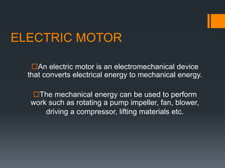
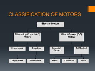
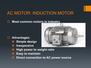
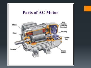
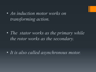
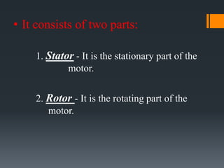

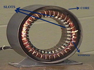
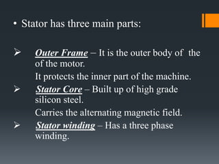
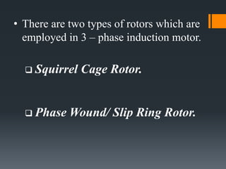
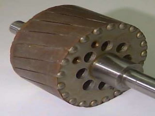
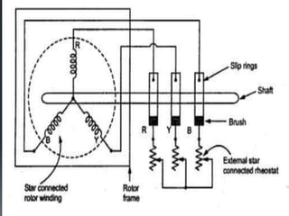
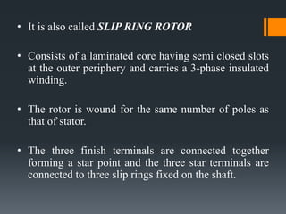
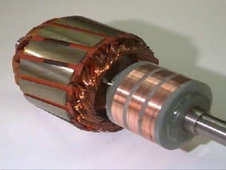
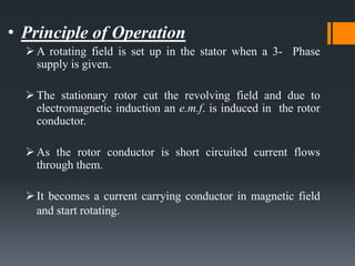
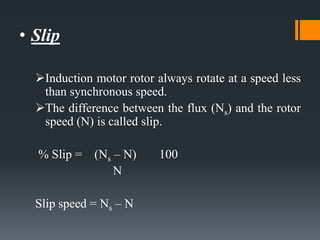
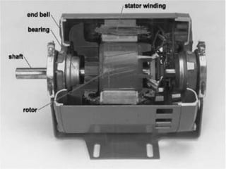
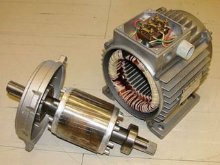
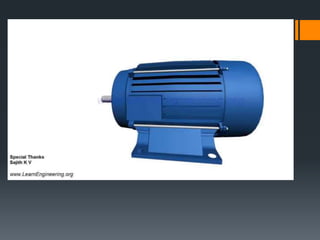


This presentation provides an overview of induction motors. It begins by defining an electric motor as a device that converts electrical energy to mechanical energy. It then classifies motors as either alternating current (AC) or direct current (DC). The presentation focuses on AC induction motors, which are the most common type used in industry due to their simple design, low cost, and ease of maintenance. It describes the basic components and operation of an induction motor, including its stator, rotor, and how rotational motion is produced through electromagnetic induction. It also discusses two common rotor types - squirrel cage and wound rotor - and defines the concept of slip in induction motors.


