Download as PDF, PPTX
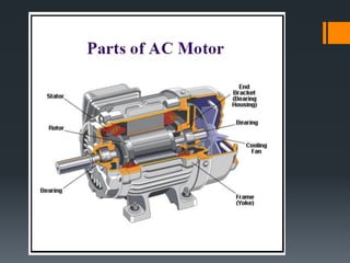
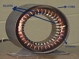
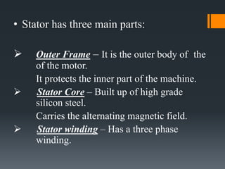
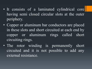
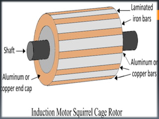
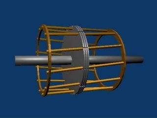
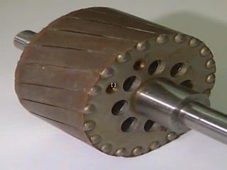
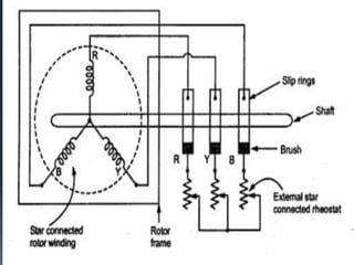
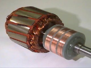
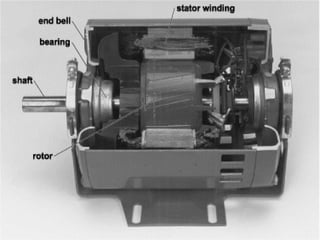
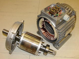


The three phase induction motor consists of a stationary stator and a rotating rotor. The stator contains three-phase windings that generate a rotating magnetic field. This rotating field induces currents in the rotor windings, causing the rotor to turn. There are two common types of rotors - squirrel cage and wound rotor. A squirrel cage rotor has embedded conductors inside its core that are permanently short-circuited. A wound rotor has three insulated windings connected to slip rings to allow external resistance control. Due to slight differences in speed, the rotor always rotates at a slightly slower synchronous speed than the stator's magnetic field.


