Downloaded 13 times
![Clock distribution in high speed board
Khodifad Pankaj
eInfochips Training and Research Academy
Sola, Ahmedabad
ABSTRACT
Clock signals toggle faster than any other signals in a digital system. For every data
transition some clock must transition twice, completing a full cycle. Not only are clocks the fastest
signals, they are also the most heavily loaded. Clocks connect to every flip-flop in a system, while
individual data wires fan out to only a few devices each. Because they are so fast and heavily
loaded, clock signals deserve special attention [3].This paper examines clock drivers, special clock
routing rule, and peculiar circuits used to improve the distribution of clock signals.
I.INTRODUCTION
One of the most carefully engineered components of a synchronous digital system is the
clock distribution network. The clock signal provides the temporal frame of reference by which
data is transferred. Thus, the tightest control of the clock is vital to correct operation of the system.
Making this design task more difficult is the fact that the clock signal typically has the most
capacitive loading, the highest fan-out, the longest distance to travel, and certainly the highest
switching frequency of any signal in the system. Compounding the problem further is the need for
very clean and sharp transitions on the clock signal, so that its edges are detected simultaneously
across the device. Industry trends in process technology and digital system design are making the
clock distribution design both more demanding and a more significant factor in overall system
performance. As technology scales, the interconnect widths become smaller, increasing the
interconnect resistance. Digital systems are also steadily increasing in frequency of operation,
nearly doubling this parameter every two years[2].The increase in interconnect resistance coupled
with the demand for faster systems has elevated the significance of the clock distribution network
on system performance.
II. TIMING MARGIN
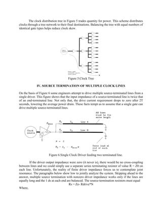
The circuit in Figure 1 is a 2-bit ring counter, also called a switch-tail counter. When
clocked at low speeds, the bit pattern at Q1 repeats forever (...00110011...). As we raise the clock
frequency in Figure 1, the circuit emits the same pattern until at some high frequency the circuit
fails. The circuit fails because of a lack of setup time for flip-flop 2. At the failure frequency, each
transition at Qi emerges from gate G too late to meet the setup time requirement of D2. Figure 2
diagrams this failure mode. When clocked at or beyond the failure frequency, the circuit no longer
produces an 0011 output sequence. This type of failure is called a timing margin failure.](https://image.slidesharecdn.com/clockdistributioninhighspeedboard-140424023936-phpapp02/85/Clock-distribution-in-high-speed-board-1-320.jpg)
![Clock distribution in high speed board
Khodifad Pankaj
eInfochips Training and Research Academy
Sola, Ahmedabad
ABSTRACT
Clock signals toggle faster than any other signals in a digital system. For every data
transition some clock must transition twice, completing a full cycle. Not only are clocks the fastest
signals, they are also the most heavily loaded. Clocks connect to every flip-flop in a system, while
individual data wires fan out to only a few devices each. Because they are so fast and heavily
loaded, clock signals deserve special attention [3].This paper examines clock drivers, special clock
routing rule, and peculiar circuits used to improve the distribution of clock signals.
I.INTRODUCTION
One of the most carefully engineered components of a synchronous digital system is the
clock distribution network. The clock signal provides the temporal frame of reference by which
data is transferred. Thus, the tightest control of the clock is vital to correct operation of the system.
Making this design task more difficult is the fact that the clock signal typically has the most
capacitive loading, the highest fan-out, the longest distance to travel, and certainly the highest
switching frequency of any signal in the system. Compounding the problem further is the need for
very clean and sharp transitions on the clock signal, so that its edges are detected simultaneously
across the device. Industry trends in process technology and digital system design are making the
clock distribution design both more demanding and a more significant factor in overall system
performance. As technology scales, the interconnect widths become smaller, increasing the
interconnect resistance. Digital systems are also steadily increasing in frequency of operation,
nearly doubling this parameter every two years[2].The increase in interconnect resistance coupled
with the demand for faster systems has elevated the significance of the clock distribution network
on system performance.
II. TIMING MARGIN
The circuit in Figure 1 is a 2-bit ring counter, also called a switch-tail counter. When
clocked at low speeds, the bit pattern at Q1 repeats forever (...00110011...). As we raise the clock
frequency in Figure 1, the circuit emits the same pattern until at some high frequency the circuit
fails. The circuit fails because of a lack of setup time for flip-flop 2. At the failure frequency, each
transition at Qi emerges from gate G too late to meet the setup time requirement of D2. Figure 2
diagrams this failure mode. When clocked at or beyond the failure frequency, the circuit no longer
produces an 0011 output sequence. This type of failure is called a timing margin failure.](https://image.slidesharecdn.com/clockdistributioninhighspeedboard-140424023936-phpapp02/75/Clock-distribution-in-high-speed-board-1-2048.jpg)
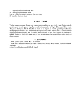
![Figure 1. 2-bit Ring Counter
Figure 2.Timing Analysis of 2bit Ring Counter
The timing margin is defined in this circuit as the amount of time remaining between
(1) The time when signals actually emerge from gate G and
(2) The time when signals at D2 must be valid to meet the setup requirement of flip-flop 2.
The timing margin measures the slack, or excess time, remaining in each clock cycle. A
system with a big timing margin on every circuit can usually run at a higher clock speed without
error.
As the clock speed in Figure 1 approaches its failure frequency, the timing mar-gin drops
to zero. Never operate a circuit near its failure frequency. Reduce the maximum operating speed
for any circuit somewhat below the failure frequency, leaving a small positive timing margin under
all operating conditions. A positive timing margin protects your circuit against signal crosstalk
which may slightly perturb the edge transition times, general miscalculations that often occur when
counting logic delays, and later minor changes in the board design or layout[1].
Many designers aim for a positive timing margin equal to about one gate delay. When
working with slow logic families, this rule of thumb allots more timing margin than when
working with fast logic families. This keeps the timing margin fixed as a percentage of delay
over a wide range of designs. You will have to decide how much excess timing margin is
acceptable.
The timing margin depends on both the delay of logic paths and the clock interval. Either
too long a delay or too short a clock interval can cause a timing margin failure. As explained in
the next section, differential delays between the clock signals CLKI and CLK2 can also cause a
timing margin failure.](https://image.slidesharecdn.com/clockdistributioninhighspeedboard-140424023936-phpapp02/85/Clock-distribution-in-high-speed-board-2-320.jpg)
![III. CLOCK SKEW
Let's take a closer look at timing margins. Figure 3 dissects our ring counter circuit,
showing the components of timing margin analysis. We seek the worst-case timing margin. Figure
3 calculates the latest possible time of arrival for pulses emerging from gate G, comparing that to
the earliest possible arrival time required by the setup conditions of flip-flop 2. The latest possible
arrival time for a pulse coming through gate G is
In Equation 1 we use maximum delay times for all elements. We also assume that the clock
pulse of interest occurs at time zero; no absolute time reference appears in Equation 1. The pulse
from G gets clocked into flip-flop 2 on the next clock pulse. This clock occurs at time TCLK and
propagates through path C2 to input CLK2. The earliest possible arrival for the next clock at CLK2
is TCLK Tc2,min• Flip-flop 2 requires a valid input at least Tsetup seconds before this CLK2. The
arrival time required by flip-flop 2 is[1].
Trequired =TCLK +TC2,min —Tsetup [2]
Where,
Trequired= elapsed time by which data from G must arrive, ns
TCLK = interval between clocks, s
TC2, min = minimum delay of path C2, s
Tsetup = worst-case setup time required by flip-flop 2, s
Figure 3.Timing Analysis showing Clock skew](https://image.slidesharecdn.com/clockdistributioninhighspeedboard-140424023936-phpapp02/85/Clock-distribution-in-high-speed-board-3-320.jpg)
![Equation 2 uses the minimum delay time for path C2, which moves the required data arrival
time to the early side. This would be the worst condition. Data from G must arrive before Trequired
to properly set flip-flop 2. In mathematical terms, we require
Tslow < Trequired
This constraint may be expanded using Equations 1 and 2.
In words, the clock interval must exceed the flip-flop delay, the gate G delay, and the setup
time. These three terms make perfect sense because all three events must occur in sequence each
cycle. The last term takes more explaining. It involves the difference in clock arrival times at nodes
CLK1 and CLK2. This difference is called clock skew. If the clock arrives late at flip-flop 1, then
output Q1 also occurs late, and our timing margin deteriorates. If delay C2 is unusually small, flip-
flop 2 gets clocked earlier, and data must be valid earlier to meet the setup time. This also
deteriorates our timing margin. In either case we must increase the clock interval, slowing down
system performance, to fix the problem. Clock skew always affects timing margins[1].
III. USING LOW-IMPEDANCE DRIVERS
The brute force method for low skew has two parts:
(1) Locate all clock inputs close together.
(2) Drive them from the same source.
If a system has many clock inputs that cannot be physically collocated, the simple brute
force method fails. In that case, try the spider distribution network. This network, drawn in Figure
4, distributes clocks from a single source to N remote destinations. Reflections are damped by
resistive terminations R at the end of each spider leg. The drive circuit experiences a total load of
RIN.
Using a transmission line impedance of 75 ohm, a network of three spider legs presents a
25-52 composite load to its driver. Some commercial chips drive loads that low, but not many.
To service more spider legs, we need a more powerful clock driver. Two or more driver outputs
connected in parallel make a convenient and simple high-powered driver. Always draw the
paralleled outputs from a common integrated circuit. Outputs from the same chip have only a small
skew between them and are thus unlikely to burn each other out when connected in parallel.
Figure 4.Spider Legs Clock Distribution](https://image.slidesharecdn.com/clockdistributioninhighspeedboard-140424023936-phpapp02/85/Clock-distribution-in-high-speed-board-4-320.jpg)

This document discusses clock distribution in high speed boards. It examines clock drivers, special clock routing rules, and circuits used to improve clock signal distribution. Precise clock distribution is important for correct system operation, as the clock provides the temporal frame of reference. Timing margin measures excess time in each clock cycle and protects against signal issues. Clock skew, or differences in clock arrival times, impacts timing margin and overall operating speed. Special techniques like low-impedance drivers, clock trees, and source termination of multiple lines can help optimize clock distribution.


![[Back2School] Constraint Develop.pdf- Chapter 3](https://cdn.slidesharecdn.com/ss_thumbnails/constraintdevelop-250606153235-d8296a49-thumbnail.jpg?width=640&height=640&fit=bounds)


![Getting Started with Apache Spark: Big Data Made Simple [Free Meetup]](https://cdn.slidesharecdn.com/ss_thumbnails/apachesparkgettingstarted-260203175547-8361bcc3-thumbnail.jpg?width=640&height=640&fit=bounds)
