Download as PDF, PPTX


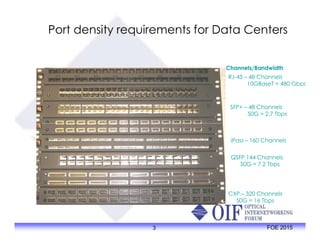
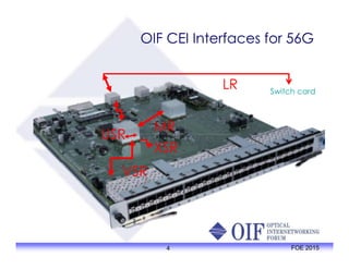
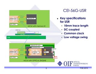
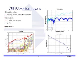
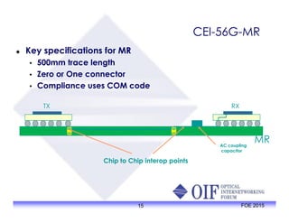
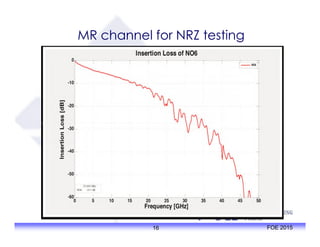
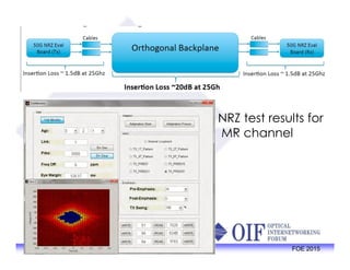
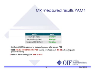
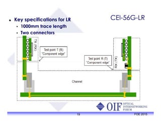
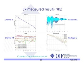
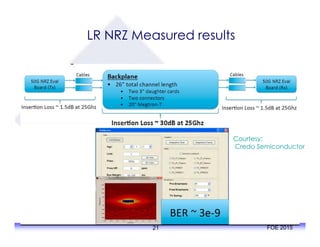

The document outlines the specifications and applications of the OIF CEI-56G electrical interfaces, including various configurations like usr, xsr, vsr, mr, and lr, with a focus on port density requirements. It discusses test results for nrz and pam4 signaling methods, highlighting the advantages and disadvantages of each in terms of performance and implementation. The OIF is actively defining solutions for future electrical interfaces, with both nrz and pam4 specifications being developed for these applications.


![Signal Integrity - A Crash Course [R Lott]](https://cdn.slidesharecdn.com/ss_thumbnails/1cb0870c-cad3-4a68-ad41-8e9450fec5d8-170217191645-thumbnail.jpg?width=640&height=640&fit=bounds)


