The document presents a smart traffic control system that measures traffic density and prioritizes emergency vehicles using a sensor network and RF communication. It outlines the system's components, working mechanism, implementation steps, and the advantages of improved traffic flow. The conclusion highlights the potential for reducing traffic congestion through the configuration of the traffic control system.
![SMART TRAFFIC
CONTROL
LEKHA M[B3ENEE3305]
THRISHNA JAYARAJ[B3ENEE3312]
SRUTHI M SURENDRAN[B3ENEE3311]
1](https://image.slidesharecdn.com/smarttrafficcontrol-171022072017/85/SMART-TRAFFIC-CONTROL-1-320.jpg)
![SMART TRAFFIC
CONTROL
LEKHA M[B3ENEE3305]
THRISHNA JAYARAJ[B3ENEE3312]
SRUTHI M SURENDRAN[B3ENEE3311]
1](https://image.slidesharecdn.com/smarttrafficcontrol-171022072017/75/SMART-TRAFFIC-CONTROL-1-2048.jpg)
![2
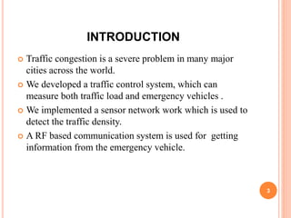
INTRODUCTION
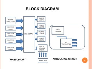
BLOCK DIAGRAM
BLOCK DIAGRAM DESCRIPTION
CIRCUIT DIAGRAM
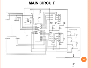
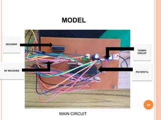
MAIN CIRCUIT
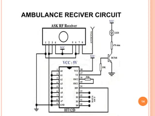
AMBULANCE RECEIVER CIRCUIT
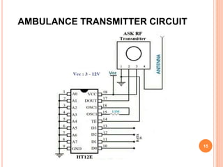
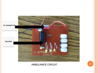
AMBULANCE TRANSMITTER CIRCUIT
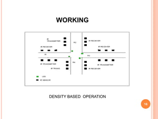
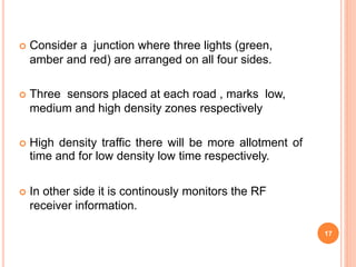
WORKING
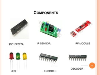
COMPONENT
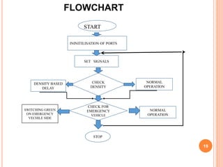
FLOW CHART
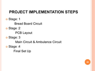
PROJECT IMPLEMENTION STEPS
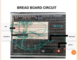
BREAD BOARD CONNECTION
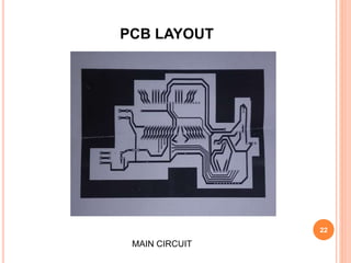
PCB LAYOUT [MAIN CIRCUIT ]
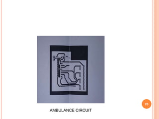
PCB LAYOUT[AMBULANCE CIRCUIT ]
MAIN CIRCUIT
AMBULANCE CIRCUIT
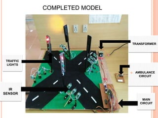
COMPLETED MODEL
ADVANTAGES
LIMITATIONS
APPLICATION
CONCLUSION
2](https://image.slidesharecdn.com/smarttrafficcontrol-171022072017/85/SMART-TRAFFIC-CONTROL-2-320.jpg)
![REFERENCE
JATES-International Journal of Advanced Technology In
Engineering and Science
Ijates.com, 2016. [Online]. Available: http://www.ijates.com.
Jameco Electronics - Electronic Components Distributor
DECORDER
Jameco.com, 2016. [Online]. Available:
http://www.jameco.com.
RFI-"RFID", Rentron.com, 2016. [Online]. Available:
http://www.rentron.com.
ELECTRONICS HUB
"Electronics Hub", Electronicshub.in, 2016. [Online]. Available:
http://www.electronicshub.in.
DATA SHEET", 2016. [Online]. Available:
http://WWW.catalog.com.
DATA SHEET” 2016. [Online]. Available:
http://WWW.electronics tutorial.com. 32](https://image.slidesharecdn.com/smarttrafficcontrol-171022072017/85/SMART-TRAFFIC-CONTROL-32-320.jpg)


![[Deck] What's New in Spark-Iceberg Integration via DSV2.pptx](https://cdn.slidesharecdn.com/ss_thumbnails/deckwhatsnewinspark-icebergintegrationviadsv2-260210005337-25955b12-thumbnail.jpg?width=640&height=640&fit=bounds)


