Downloaded 1,350 times
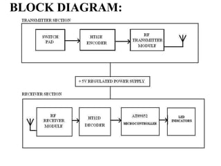
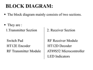
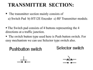
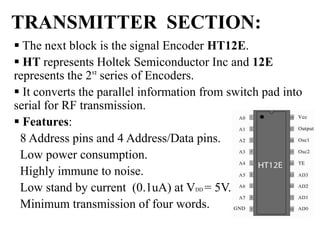
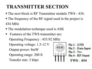
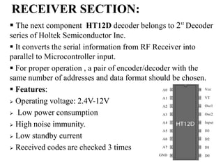
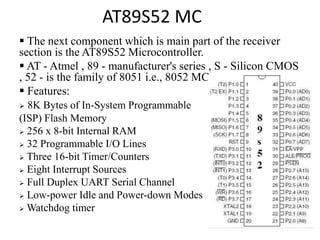
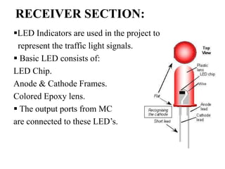
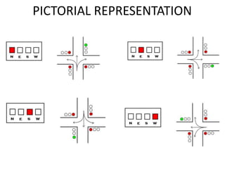


This document describes a wireless traffic light priority control system for emergency vehicles. The system has a transmitter section in emergency vehicles that sends signals to a receiver section connected to traffic lights. The transmitter section consists of switches to select light directions, an encoder to convert switch signals to radio waves, and an RF transmitter. The receiver section has an RF receiver to get signals, a decoder to convert them to microcontroller input, an AT89S52 microcontroller to control lights, and LED indicators representing traffic lights. The system is intended to prioritize green lights for emergency vehicles to reduce traffic delays.