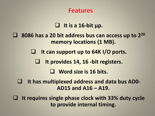
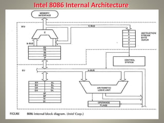
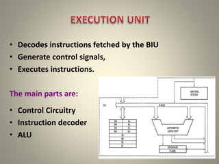
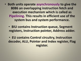
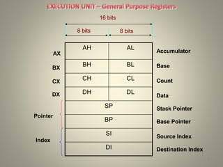
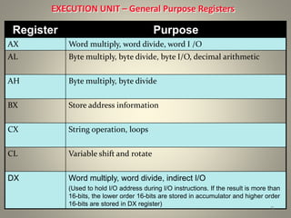
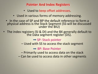
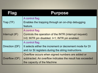
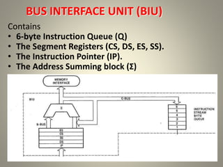
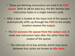
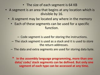
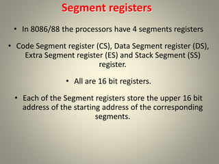
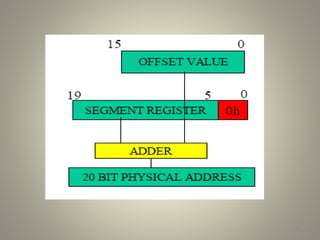
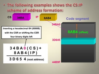
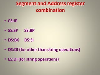
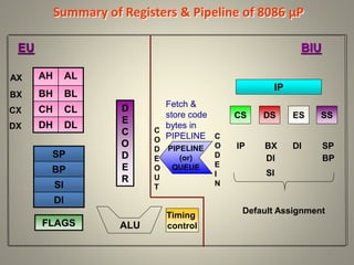
INTEL 8086
MICROPROCESSOR
Kuntumal Sagar M.
B.TECH (E.E)
UID-U41000000484
Email: skuntmal@yahoo.com
TOPIC
Introduction
Features
 It is a 16-bit μp.
 8086 has a 20 bit address bus can access up to 220
memory locations (1 MB).
 It can support up to 64K I/O ports.
 It provides 14, 16 -bit registers.
 Word size is 16 bits.
 It has multiplexed address and data bus AD0-
AD15 and A16 – A19.
 It requires single phase clock with 33% duty cycle
to provide internal timing.
2
 8086 is designed to operate in two modes, Minimum
and Maximum.
 It can prefetches up to 6 instruction bytes from
memory and queues them in order to speed up
instruction execution.
 It requires +5V power supply.
 A 40 pin dual in line package.
 Address ranges from 00000H to FFFFFH
 Memory is byte addressable - Every byte has a
separate address.
3
Intel 8086 Internal Architecture
4
Internal architecture of 8086
• 8086 has two blocks BIU and EU.
• The BIU handles all transactions of data and addresses
on the buses for EU.
• The BIU performs all bus operations such as instruction
fetching, reading and writing operands for memory and
calculating the addresses of the memory operands. The
instruction bytes are transferred to the instruction
queue.
• EU executes instructions from the instruction system
byte queue.
5
• Decodes instructions fetched by the BIU
• Generate control signals,
• Executes instructions.
The main parts are:
• Control Circuitry
• Instruction decoder
• ALU
6
• Both units operate asynchronously to give the
8086 an overlapping instruction fetch and
execution mechanism which is called as
Pipelining. This results in efficient use of the
system bus and system performance.
• BIU contains Instruction queue, Segment
registers, Instruction pointer, Address adder.
• EU contains Control circuitry, Instruction
decoder, ALU, Pointer and Index register, Flag
register.
7
AH AL
BH BL
CH CL
DH DL
SP
BP
SI
DI
8
8 bits 8 bits
16 bits
Accumulator
Base
Count
Data
Stack Pointer
Base Pointer
Source Index
Destination Index
AX
BX
CX
DX
Pointer
Index
8 bits 8 bits
16 bits
Accumulator
Base
Count
Data
Stack Pointer
Base Pointer
Source Index
Destination Index
EXECUTION UNIT – General Purpose Registers
Register Purpose
AX Word multiply, word divide, word I /O
AL Byte multiply, byte divide, byte I/O, decimal arithmetic
AH Byte multiply, byte divide
BX Store address information
CX String operation, loops
CL Variable shift and rotate
DX Word multiply, word divide, indirect I/O
(Used to hold I/O address during I/O instructions. If the result is more than
16-bits, the lower order 16-bits are stored in accumulator and higher order
16-bits are stored in DX register)
9
Pointer And Index Registers
• Used to keep offset addresses.
• Used in various forms of memory addressing.
• In the case of SP and BP the default reference to form a
physical address is the Stack Segment (SS-will be discussed
under the BIU)
• The index registers (SI & DI) and the BX generally default to
the Data segment register (DS).
SP: Stack pointer
– Used with SS to access the stack segment
BP: Base Pointer
– Primarily used to access data on the stack
– Can be used to access data in other segments
10
• SI: SOURCE INDEX REGISTER
– is required for some string operations
– When string operations are performed, the SI
register points to memory locations in the data
segment which is addressed by the DS register.
Thus, SI is associated with the DS in string operations.
• DI: DESTINATION INDEX REGISTER
– is also required for some string operations.
– When string operations are performed, the DI
register points to memory locations in the data
segment which is addressed by the ES register.
Thus, DI is associated with the ES in string operations.
• The SI and the DI registers may also be used to access
data stored in arrays 11
EXECUTION UNIT – Flag Register
U U U U OF DF IF TF SF ZF U AF U PF U CF
12
• A flag is a flip flop which indicates some conditions
produced by the execution of an instruction or
controls certain operations of the EU .
• In 8086 The EU contains
a 16 bit flag register
9 of the 16 are active flags and remaining 7 are
undefined.
6 flags indicates some conditions- status flags
3 flags –control Flags Carry
Over flow Direction
Interrupt Trap
Sign
Zero
Auxiliary
Parity
U - Unused
EXECUTION UNIT – Flag Register
Flag Purpose
Carry (CF) Holds the carry after addition or the borrow after subtraction.
Also indicates some error conditions, as dictated by some
programs and procedures .
Parity (PF) PF=0;odd parity, PF=1;even parity.
Auxiliary (AF) Holds the carry (half – carry) after addition or borrow after
subtraction between bit positions 3 and 4 of the result
(for example, in BCD addition or subtraction.)
Zero (ZF) Shows the result of the arithmetic or logic operation.
Z=1; result is zero. Z=0; The result is 0
Sign (SF) Holds the sign of the result after an arithmetic/logic instruction
execution. S=1; negative, S=0 13
Flag Purpose
Trap (TF)
A control flag.
Enables the trapping through an on-chip debugging
feature.
Interrupt (IF)
A control flag.
Controls the operation of the INTR (interrupt request)
I=0; INTR pin disabled. I=1; INTR pin enabled.
Direction (DF)
A control flag.
It selects either the increment or decrement mode for DI
and /or SI registers during the string instructions.
Overflow (OF)
Overflow occurs when signed numbers are added or
subtracted. An overflow indicates the result has exceeded
the capacity of the Machine
14
Execution unit – Flag Register
• Six of the flags are status indicators reflecting properties
of the last arithmetic or logical instruction.
• For example, if register AL = 7Fh and the instruction ADD
AL,1 is executed then the following happen
AL = 80h
CF = 0; there is no carry out of bit 7
PF = 0; 80h has an odd number of ones
AF = 1; there is a carry out of bit 3 into bit 4
ZF = 0; the result is not zero
SF = 1; bit seven is one
OF = 1; the sign bit has changed
15
BUS INTERFACE UNIT (BIU)
Contains
• 6-byte Instruction Queue (Q)
• The Segment Registers (CS, DS, ES, SS).
• The Instruction Pointer (IP).
• The Address Summing block (Σ)
16
THE QUEUE (Q)
• The BIU uses a mechanism known as an instruction
stream queue to implement a pipeline architecture.
• This queue permits pre-fetch of up to 6 bytes of
instruction code. Whenever the queue of the BIU is not
full, it has room for at least two more bytes and at the
same time the EU is not requesting it to read or write
operands from memory, the BIU is free to look ahead in
the program by pre-fetching the next sequential
instruction.
17
• These pre-fetching instructions are held in its FIFO
queue. With its 16 bit data bus, the BIU fetches two
instruction bytes in a single memory cycle.
• After a byte is loaded at the input end of the queue, it
automatically shifts up through the FIFO to the empty
location nearest the output.
• The EU accesses the queue from the output end. It
reads one instruction byte after the other from the
output of the queue.
• The intervals of no bus activity, which may occur
between bus cycles are known as Idle state.
18
Segmented
Memory
Code segment (64KB)
Data segment (64KB)
Extra segment (64KB)
Stack segment (64KB)
19
1
MB
The memory in an 8086/88
based system is organized as
segmented memory.
The CPU 8086 is able to
address 1Mbyte of memory.
The Complete physically
available memory may be
divided into a number of logical
segments.
00000
FFFFF
Physical Memory
• The size of each segment is 64 KB
• A segment is an area that begins at any location which is
divisible by 16.
• A segment may be located any where in the memory
• Each of these segments can be used for a specific
function.
– Code segment is used for storing the instructions.
– The stack segment is used as a stack and it is used to store
the return addresses.
– The data and extra segments are used for storing data byte.
* In the assembly language programming, more than one
data/ code/ stack segments can be defined. But only one
segment of each type can be accessed at any time.
20
• The 4 segments are Code, Data, Extra and Stack
segments.
• A Segment is a 64kbyte block of memory.
• The 16 bit contents of the segment registers in the
BIU actually point to the starting location of a
particular segment.
• Segments may be overlapped or non-overlapped
Advantages of Segmented memory Scheme
• Allows the memory capacity to be 1Mb although the actual addresses to be
handled are of 16 bit size.
• Allows the placing of code, data and stack portions of the same program in different
parts (segments) of the m/y, for data and code protection.
• Permits a program and/or its data to be put into different areas of memory each
time program is executed, i.e. provision for relocation may be done .
• The segment registers are used to allow the instruction, data or stack portion of a
program to be more than 64Kbytes long. The above can be achieved by using more
than one code, data or stack segments.
21
Segment registers
• In 8086/88 the processors have 4 segments registers
• Code Segment register (CS), Data Segment register (DS),
Extra Segment register (ES) and Stack Segment (SS)
register.
• All are 16 bit registers.
• Each of the Segment registers store the upper 16 bit
address of the starting address of the corresponding
segments.
22
23
34BA
44EB
54EB
695E
24
CSR
DSR
ESR
SSR
Segment Registers
BIU
CODE (64k)
DATA (64K)
EXTRA (64K)
STACK (64K)
1
MB
00000
34BA0
44B9F
44EB0
54EAF
54EB0
64EAF
695E0
795DF
Each segment register store the
upper 16 bit of the starting address
of the segments
MEMORY
Instruction pointer & summing block
• The instruction pointer register contains a 16-bit offset
address of instruction that is to be executed next.
• The IP always references the Code segment register (CS).
• The value contained in the instruction pointer is called as
an offset because this value must be added to the base
address of the code segment, which is available in the CS
register to find the 20-bit physical address.
• The value of the instruction pointer is incremented after
executing every instruction.
• To form a 20bit address of the next instruction, the 16 bit
address of the IP is added (by the address summing block)
to the address contained in the CS , which has been
shifted four bits to the left.
25
26
27
Inserting a hexadecimal 0H (0000B)
with the CSR or shifting the CSR
four binary digits left
3 4 B A 0 ( C S ) +
8 A B 4 ( I P )
3 D 6 5 4 (next address)
34BA 8AB4
CS IP
34BA0
3D645
44B9F
Code segment
8AB4 (offset)
• Example For Address Calculation (segment:
offset)
• If the data segment starts at location 1000h and
a data reference contains the address 29h where
is the actual data?
28
Required Address
Offset
Segment Address
0000 0000 0010 1001
0000
0001 0000 0000 0010 1001
0001 0000 0000 0000
Segment and Address register
combination
• CS:IP
• SS:SP SS:BP
• DS:BX DS:SI
• DS:DI (for other than string operations)
• ES:DI (for string operations)
29
Summary of Registers & Pipeline of 8086 µP
AH AL
BH BL
CH CL
DH DL
30
SP
BP
SI
DI
FLAGS
D
E
C
O
D
E
R
ALU
AX
BX
CX
DX
EU
Timing
control
SP
BP
Default Assignment
BIU
IP
CS DS ES SS
PIPELINE
(or)
QUEUE
C
O
D
E
O
U
T
C
O
D
E
I
N
IP BX
DI
SI
DI
Fetch &
store code
bytes in
PIPELINE
31

INTEL 8086 MICROPROCESSOR

  • 1.
    INTEL 8086 MICROPROCESSOR Kuntumal SagarM. B.TECH (E.E) UID-U41000000484 Email: skuntmal@yahoo.com TOPIC Introduction
  • 2.
    Features  It isa 16-bit μp.  8086 has a 20 bit address bus can access up to 220 memory locations (1 MB).  It can support up to 64K I/O ports.  It provides 14, 16 -bit registers.  Word size is 16 bits.  It has multiplexed address and data bus AD0- AD15 and A16 – A19.  It requires single phase clock with 33% duty cycle to provide internal timing. 2
  • 3.
     8086 isdesigned to operate in two modes, Minimum and Maximum.  It can prefetches up to 6 instruction bytes from memory and queues them in order to speed up instruction execution.  It requires +5V power supply.  A 40 pin dual in line package.  Address ranges from 00000H to FFFFFH  Memory is byte addressable - Every byte has a separate address. 3
  • 4.
    Intel 8086 InternalArchitecture 4
  • 5.
    Internal architecture of8086 • 8086 has two blocks BIU and EU. • The BIU handles all transactions of data and addresses on the buses for EU. • The BIU performs all bus operations such as instruction fetching, reading and writing operands for memory and calculating the addresses of the memory operands. The instruction bytes are transferred to the instruction queue. • EU executes instructions from the instruction system byte queue. 5
  • 6.
    • Decodes instructionsfetched by the BIU • Generate control signals, • Executes instructions. The main parts are: • Control Circuitry • Instruction decoder • ALU 6
  • 7.
    • Both unitsoperate asynchronously to give the 8086 an overlapping instruction fetch and execution mechanism which is called as Pipelining. This results in efficient use of the system bus and system performance. • BIU contains Instruction queue, Segment registers, Instruction pointer, Address adder. • EU contains Control circuitry, Instruction decoder, ALU, Pointer and Index register, Flag register. 7
  • 8.
    AH AL BH BL CHCL DH DL SP BP SI DI 8 8 bits 8 bits 16 bits Accumulator Base Count Data Stack Pointer Base Pointer Source Index Destination Index AX BX CX DX Pointer Index 8 bits 8 bits 16 bits Accumulator Base Count Data Stack Pointer Base Pointer Source Index Destination Index
  • 9.
    EXECUTION UNIT –General Purpose Registers Register Purpose AX Word multiply, word divide, word I /O AL Byte multiply, byte divide, byte I/O, decimal arithmetic AH Byte multiply, byte divide BX Store address information CX String operation, loops CL Variable shift and rotate DX Word multiply, word divide, indirect I/O (Used to hold I/O address during I/O instructions. If the result is more than 16-bits, the lower order 16-bits are stored in accumulator and higher order 16-bits are stored in DX register) 9
  • 10.
    Pointer And IndexRegisters • Used to keep offset addresses. • Used in various forms of memory addressing. • In the case of SP and BP the default reference to form a physical address is the Stack Segment (SS-will be discussed under the BIU) • The index registers (SI & DI) and the BX generally default to the Data segment register (DS). SP: Stack pointer – Used with SS to access the stack segment BP: Base Pointer – Primarily used to access data on the stack – Can be used to access data in other segments 10
  • 11.
    • SI: SOURCEINDEX REGISTER – is required for some string operations – When string operations are performed, the SI register points to memory locations in the data segment which is addressed by the DS register. Thus, SI is associated with the DS in string operations. • DI: DESTINATION INDEX REGISTER – is also required for some string operations. – When string operations are performed, the DI register points to memory locations in the data segment which is addressed by the ES register. Thus, DI is associated with the ES in string operations. • The SI and the DI registers may also be used to access data stored in arrays 11
  • 12.
    EXECUTION UNIT –Flag Register U U U U OF DF IF TF SF ZF U AF U PF U CF 12 • A flag is a flip flop which indicates some conditions produced by the execution of an instruction or controls certain operations of the EU . • In 8086 The EU contains a 16 bit flag register 9 of the 16 are active flags and remaining 7 are undefined. 6 flags indicates some conditions- status flags 3 flags –control Flags Carry Over flow Direction Interrupt Trap Sign Zero Auxiliary Parity U - Unused
  • 13.
    EXECUTION UNIT –Flag Register Flag Purpose Carry (CF) Holds the carry after addition or the borrow after subtraction. Also indicates some error conditions, as dictated by some programs and procedures . Parity (PF) PF=0;odd parity, PF=1;even parity. Auxiliary (AF) Holds the carry (half – carry) after addition or borrow after subtraction between bit positions 3 and 4 of the result (for example, in BCD addition or subtraction.) Zero (ZF) Shows the result of the arithmetic or logic operation. Z=1; result is zero. Z=0; The result is 0 Sign (SF) Holds the sign of the result after an arithmetic/logic instruction execution. S=1; negative, S=0 13
  • 14.
    Flag Purpose Trap (TF) Acontrol flag. Enables the trapping through an on-chip debugging feature. Interrupt (IF) A control flag. Controls the operation of the INTR (interrupt request) I=0; INTR pin disabled. I=1; INTR pin enabled. Direction (DF) A control flag. It selects either the increment or decrement mode for DI and /or SI registers during the string instructions. Overflow (OF) Overflow occurs when signed numbers are added or subtracted. An overflow indicates the result has exceeded the capacity of the Machine 14
  • 15.
    Execution unit –Flag Register • Six of the flags are status indicators reflecting properties of the last arithmetic or logical instruction. • For example, if register AL = 7Fh and the instruction ADD AL,1 is executed then the following happen AL = 80h CF = 0; there is no carry out of bit 7 PF = 0; 80h has an odd number of ones AF = 1; there is a carry out of bit 3 into bit 4 ZF = 0; the result is not zero SF = 1; bit seven is one OF = 1; the sign bit has changed 15
  • 16.
    BUS INTERFACE UNIT(BIU) Contains • 6-byte Instruction Queue (Q) • The Segment Registers (CS, DS, ES, SS). • The Instruction Pointer (IP). • The Address Summing block (Σ) 16
  • 17.
    THE QUEUE (Q) •The BIU uses a mechanism known as an instruction stream queue to implement a pipeline architecture. • This queue permits pre-fetch of up to 6 bytes of instruction code. Whenever the queue of the BIU is not full, it has room for at least two more bytes and at the same time the EU is not requesting it to read or write operands from memory, the BIU is free to look ahead in the program by pre-fetching the next sequential instruction. 17
  • 18.
    • These pre-fetchinginstructions are held in its FIFO queue. With its 16 bit data bus, the BIU fetches two instruction bytes in a single memory cycle. • After a byte is loaded at the input end of the queue, it automatically shifts up through the FIFO to the empty location nearest the output. • The EU accesses the queue from the output end. It reads one instruction byte after the other from the output of the queue. • The intervals of no bus activity, which may occur between bus cycles are known as Idle state. 18
  • 19.
    Segmented Memory Code segment (64KB) Datasegment (64KB) Extra segment (64KB) Stack segment (64KB) 19 1 MB The memory in an 8086/88 based system is organized as segmented memory. The CPU 8086 is able to address 1Mbyte of memory. The Complete physically available memory may be divided into a number of logical segments. 00000 FFFFF Physical Memory
  • 20.
    • The sizeof each segment is 64 KB • A segment is an area that begins at any location which is divisible by 16. • A segment may be located any where in the memory • Each of these segments can be used for a specific function. – Code segment is used for storing the instructions. – The stack segment is used as a stack and it is used to store the return addresses. – The data and extra segments are used for storing data byte. * In the assembly language programming, more than one data/ code/ stack segments can be defined. But only one segment of each type can be accessed at any time. 20
  • 21.
    • The 4segments are Code, Data, Extra and Stack segments. • A Segment is a 64kbyte block of memory. • The 16 bit contents of the segment registers in the BIU actually point to the starting location of a particular segment. • Segments may be overlapped or non-overlapped Advantages of Segmented memory Scheme • Allows the memory capacity to be 1Mb although the actual addresses to be handled are of 16 bit size. • Allows the placing of code, data and stack portions of the same program in different parts (segments) of the m/y, for data and code protection. • Permits a program and/or its data to be put into different areas of memory each time program is executed, i.e. provision for relocation may be done . • The segment registers are used to allow the instruction, data or stack portion of a program to be more than 64Kbytes long. The above can be achieved by using more than one code, data or stack segments. 21
  • 22.
    Segment registers • In8086/88 the processors have 4 segments registers • Code Segment register (CS), Data Segment register (DS), Extra Segment register (ES) and Stack Segment (SS) register. • All are 16 bit registers. • Each of the Segment registers store the upper 16 bit address of the starting address of the corresponding segments. 22
  • 23.
  • 24.
    34BA 44EB 54EB 695E 24 CSR DSR ESR SSR Segment Registers BIU CODE (64k) DATA(64K) EXTRA (64K) STACK (64K) 1 MB 00000 34BA0 44B9F 44EB0 54EAF 54EB0 64EAF 695E0 795DF Each segment register store the upper 16 bit of the starting address of the segments MEMORY
  • 25.
    Instruction pointer &summing block • The instruction pointer register contains a 16-bit offset address of instruction that is to be executed next. • The IP always references the Code segment register (CS). • The value contained in the instruction pointer is called as an offset because this value must be added to the base address of the code segment, which is available in the CS register to find the 20-bit physical address. • The value of the instruction pointer is incremented after executing every instruction. • To form a 20bit address of the next instruction, the 16 bit address of the IP is added (by the address summing block) to the address contained in the CS , which has been shifted four bits to the left. 25
  • 26.
  • 27.
    27 Inserting a hexadecimal0H (0000B) with the CSR or shifting the CSR four binary digits left 3 4 B A 0 ( C S ) + 8 A B 4 ( I P ) 3 D 6 5 4 (next address) 34BA 8AB4 CS IP 34BA0 3D645 44B9F Code segment 8AB4 (offset)
  • 28.
    • Example ForAddress Calculation (segment: offset) • If the data segment starts at location 1000h and a data reference contains the address 29h where is the actual data? 28 Required Address Offset Segment Address 0000 0000 0010 1001 0000 0001 0000 0000 0010 1001 0001 0000 0000 0000
  • 29.
    Segment and Addressregister combination • CS:IP • SS:SP SS:BP • DS:BX DS:SI • DS:DI (for other than string operations) • ES:DI (for string operations) 29
  • 30.
    Summary of Registers& Pipeline of 8086 µP AH AL BH BL CH CL DH DL 30 SP BP SI DI FLAGS D E C O D E R ALU AX BX CX DX EU Timing control SP BP Default Assignment BIU IP CS DS ES SS PIPELINE (or) QUEUE C O D E O U T C O D E I N IP BX DI SI DI Fetch & store code bytes in PIPELINE
  • 31.