SlideShare a Scribd company logo
1
Supervisory control & Data Acquisition
(SCADA) systems on I.R.
• Indian Railways is having SCADA system for
controlling 25 kV electric traction supply since 1976.
• SCADA is meant for controlling switching ON / OFF of
circuit breakers, interrupters at unmanned traction
substations (TSSs) and switching stations located along
the track.
• SCADA is also used for data acquisition from field.
• Control is exercised through a centrally located Remote
Control Center (RCC).
• I.R. controls 25 kV Traction Supply of 17000 kms of
electrified territory through approx 53 Remote Control
Centers
2
Modem Modem
Main
Communication
Processor
Hot Standby
Communication
Processor
1a
10/100 MBPS TCP/IP LAN
Modem
Modem
1b
Main SCADA
Server with
HDS
Hot Standby
SCADA Server
with HDS
Operator Workstation
2a 2b
Operator Workstation
DOT/OFC Cable
Controlled Post
PANKI
SSP
KANPUR ( W )
SP
SIRATHU
FP
KUNWAR
SP
KHAGA
SSP
RASULABAD
TSS
FAIZULLAHPUR
SP
FATEHPUR
SSP
MALWAN
FP
BINDKI ROAD
SP
KARBIGWAN
SSP
SARSAUL
TSS
CHAKERI
SSP
KANPUR ( E )
SP
SUJATPUR
SSP
BHARWARI
SP
SAIYAD
SSP
MANAURI
TSS
BAMRAULI
SP
ALLAHABAD
SSP
NAINI
FP
JEONATHPUR
SSP
JEONATHPUR
TSS
AHRAURA
SP
CHUNAR
FP
PAHARA
SP
MIRZAPUR
TSS
BIROHE
SP
JIGNA
FP
UNCHDIH
SP
BHEERPUR
TSS
KARCHNA
SP
WAN 1 (MGS -ALD )
WAN 2 (ALD -PNK )
SCADA Equipment
3
Block Diagram of SCADA
Man Machine Interactive (PC)
Host computer (PC)
Front End Processor(PC)
RCC
modem
modem
R
T
U
modem
R
T
U
modem
R
T
U
modem
R
T
U
modem
R
T
U
modem
R
T
U
4
Modern SCADA equipments e.g.
RTU, MODEM & CPU
5
SCADA SYSTEM COMPRISES OF
THE FOLLOWING
• REMOTE CONTROL CENTRE
(RCC)
• REMOTE TERMINAL UNIT (RTU)
• COMMUNICATION MEDIUM
6
FRONT END PROCESSOR
• Two Front End Processors One Main and
Other Standby( One Hot Standby )
• IF Both FEP Fails than one of MMI can be
made as FEP.(Cold Standby)
• Coded information from field are first
received by the Modem and then Modem
after digitizing gives it to FEP .
• FEP software validates and receives valid
data only other are rejected.
7
Host computer
• Host computer is main SCADA Computer
having overall control on all other
computers.
• There are Two Host computers one is main
and other is Hot Standby.
• Addition deletion of RTUs and other
configuration application is carried out from
Host Computer.
8
Host computer(Contd.)
• Host computer processes and decode the
information received and sends it to MMI
for Display.
• Similarly the command issued by operator
from MMI first received by Host and
generates data packets and send these
packets to FEP for further transmission on
Line
9
MAN MACHINE INTERFACE
MMI
• MMI Displays the Single Line Diagram of
Traction Power supply.
• The Information received from Host is
displayed at relevant place on Mimic
diagram.
• Operator issues Telecommand on MMI
which is processed through Host & FEP as
explained.
10
MMI(Contd.)
• Man Machine Interface(MMI) provides basis
for all interactions between operator and
SCADA system
• A full graphics MMI presents the monitored
parameters in an easy to understand
graphical display.
• It also provides features to attract attention of
operator visually on occurrence of alarms.
11
MMI (Contd.)
• System also provides three security levels for
access to different operations.
• a) Traction Power Controller level:- access to
view and control.
• b) RCC Engineer:- Access to edit
configuration, add user(TPC) in addition to
above.
• c) Higher level:-Facility to add RCC
engineer and manage user permission in
addition to above two.
• All actions are menu driven and prompting
such that errors are minimum.
12
Flow diagram 1
M
RTU
Modem
FEP
PC
• Command Flow diagram RCC To RTU
HOST
PC
MMI
PC
Operator
Analog signal digital signal
13
Flow diagram 2
• Command Flow diagram RTU To RCC
HOST
PC
Operator
M
FEP
PC
MMI
PC
RTU
M
Analog signal digital signal
14
SOFTWARE FEATURES
(Telecommands)
• Execution of telecommands
• Time synchronisation of RTU and RCC
• Test procedure to check communication health
• “OFF” Scanning of RTUs to isolate defective
RTUs.
• Downloading of parameters from RCC to RTU
• Diagnostic of RTU’s from RCC upto card level
15
• Interlocking of devices to avoid undesirable
operations.
• Locked out signals for various devices.
• Printing of data & Reports
• Monitoring of Power block like alarms and
their logging.
• Audible Alarm.
SOFTWARE FEATURES
(configuration)
16
SOFTWARE FEATURES
(configuration)
• Maximum Demand(MD) monitoring.
• Under voltage range setting at SP’ RTUs for
tripping under extended feel conditions.
• Auto Fault Localisation .-software prompts
TPC to start AFL
• Picture editor- To add/delete device etc.
17
REMOTE TERMINAL UNIT
• RTU is common interface between Field
devices and RCC
• RTU is Microprocessor based logic system.
• Accepts digital and analog input signals
from field
• Receives control command from RCC.
• Replies information asked by RCC.
18
RTU Architectural Details
• Power Supply Unit
• CPU
• Digital Input Module (DIM)
• Digital Output Module (DOM)
• Analog Input Module (AIM)
• Signal Conditioning Card
19
RTU Architectural Details(Contd.)
• Modem-For Modulation and Demodulation
• Contactors- To extend 110 supply to field
devices for operation.
• Transducers: For Voltage , Current and
Power factor measurement
20
BASIC BLOCK DIAGRAM
OF RTU
• Battery 240 V AC
CPU DIT DOT AIT
Power supply unit
Modem
Trans-
ducers
Tx Rx
C O N T A C T O R
S.C.Card
input from Field devices
21
RTU FUNCTIONAL DETAIL CPU
• CPU: Microprocessor based logic System
coupled with firmware Programming
performs as a brain of RTU
• 16 bit device
• 20 MHz Speed
• Built in RAM/Backup EPROM-128 KB
• Watchdog Timer
22
Digital Input Module(DIM)
• Digital Input module provide Input point
for Status Information to CPU.
• This provides bistate field devices status to
CPU of RTU.
• Digital Input module accepts input from
field via Signal conditioning card
23
Digital Output Module(DOM)
• Digital Output module receives Output from
CPU.
• The output signal from DOM derives a
interposing relay/Opto-coupler which in
turn extend 110 dc supply to contactor
• The Contactor extend supply to Field
device for operation.
• Each device has separate contactor for each
open and close operation
24
Analog Input Module(AIM)
• Transducers receives analog signals from
CTs /PTs.
• Transducers convert them to proportional
digital values.
• These values are fed to Analog Input
module(AIT) and then to CPU.
• CPU transmits them to RCC as per protocol
25
STATUS &TELESIGNAL FLOW
DIAGRAM
T DIM Mod
em
Mod
em
FEP
Host
MMI
TPC
RCC
CPU
• .
SC card
Field
device
RTU
26
TELEMETRY FLOW DIAGRAM
.
CT/
PT
Transduc
er
AIM CPU Mod
em
Mod
em
FEP
Host
MMI
TPC
Field
RCC
RTU
27
WHAT IS A PROTOCOL ?
• What is a Communication Protocol ?- A
defined rules and regulations for
Communication between two Intelligent
devices. i.e. between RCC and RTU.
• Why a standard Protocol? To ensure
interchangeability of RTU of different
vendors.
• Based on International Standard IEC-870-5
Standard Communication Protocol is based
on IEC-870-5 .
28
Equipment layout of standard system
at RCC
29
29
Maintenance of Remote Control
Centre / RTU
Remote Control Centre
• Monthly Schedule
Dust cleaning
Level checking (RCC & POST)
• Half Yearly Schedule
Dust cleaning
Level checking (RCC & POST)
Voltage / Current checking
30
30
Maintenance of Remote Control
Centre / RTU (Contd.)
Remote Control Centre
• Yearly Schedule
Dust cleaning
Slot & contact cleaning with contact cleaner
Level checking (RCC & POST)
Voltage / Current checking
31
31
Maintenance of Remote Control
Centre / RTU (Contd.)
Remote Terminal Unit
• Half Yearly Schedule
Dust cleaning
Level checking (RCC & POST)
Voltage / Current checking
• Yearly Schedule
Repeat half yearly schedule
Slot & contact cleaning with contact cleaner
32
32
Maintenance of Remote Control
Centre / RTU (Contd.)
Remote Terminal Unit
• Four Yearly Schedule
Dust cleaning
Slot & contact cleaning with contact cleaner
Remove all cards/module clean & refix
Level checking (RCC & POST)
Voltage / Current checking
33
Traction Power Control (TPC)
Organization
RCC
• Heart of Control System
• Manned 365x24
• No operation in system without TPC approval
Traction Power Controller
• Contact with power supply authority
• Liasion with section controller
• Breakdown. Co-ordination & control
• Record Maintenance, Log Books, Shift registers
34
Traction Power Control Organization
(Contd.)
• Isolation of Faulty Section.
• Faulty Section to be kept isolated.
• Advice to Section Controller.
• Information to Traction Staff.
• Action to Rectify Fault.
• Monitoring faults on Railway Equipments,
Grid, Power supply.
34
35
Emergency Arrangement
• T&P Spares in TOWER WAGON/
TRUCK/ART
• Vehicle Truck/TW/Jeep/Wiring train
• Emergency Stores
• Emergency staff
• Emergency telephone
• Role of TPC
35
36
Co-Ordination with Operating
& other departments
OPERATING
 Request for Power Blocks from traffic department.
 Tower wagon movement control.
ENGINEERING
 Power block for P Way maintenance.
 Bonds maintenance
 Maintenance of overhead structures.
36
37
Co-Ordination with Operating &
other departments (Contd.)
S&T
• TPC/ SCADA/ Emergency Telephoning Circuit
operation
• Protection of signal structures (Earthing/Bonding)
• AT supply to CLS panel.
• BT/RC Circuit
37
38
Liaison with Power Supply
Authorities
• Agreement between Railway Authority &
Supply Authority.
• Periodic meeting meetings at different level.
• Reliability of supply & maintenance of
voltage frequency.
• Treated as essential load
• Frequent Power Supply interruption.
• Power line crossing maintenance issues.
38
39
Liaison with Power Supply
Authorities (Contd.)
• Supply failure actions
• Tariff revision issues
• Load revision issues
• Reliability of SEB protection system
• Maximum demand management.
39
40
Safety Precautions for Electric Section
(Contd.)
Rules For S&T Installation
• Effect of OHE on S&T Equipment.
• Precaution in Event of Breakage of wires.
• Working on Signal Post & Fittings.
• Precaution against built up of Potential due
to Return Current in Rails.
• Induction Potential in Metallic.
40
41
Safety Precautions for Electric Section
(Contd.)
Over-Dimensioned Consignment
• Precautions for movement of ODCs.
• Power Block for movement of ODC.
Other Precautions
• Hoarding Boards.
• Rubber Tyred Vehicles on Railway Wagons
• Loading & Unloading of Petroleum Product
41
42
Safety Precautions for Electric Section
(Contd.)
Rules Applicable to P-Way staff.
• Continuity of Track.
• Permanent Way Tools.
• Track-Circuited Rails.
• Care in Handling Pipes etc.
• Steel Measuring Tapes not to be used.
• Traction Structure Foundation.
42
43
Safety Precautions for Electric Section
Watering of carriages
• Watering Section
• Controlling Switches
• Sequence of Interlocking & Operation.
• Authorized to open Interrupters & Isolators.
• Custody of Keys, Watering of Carriage.
• Restoration of supply.
43
44
TRACTION STORES & ITS
ACCOUNTAL
Main Central Depot
• Sub Depot Store (OHE & PSI Depots)
• Emergency Store
• Store at Tower Wagon/Tuck
• T&P/Spares/Consumable
• Ledgers maintained at sub depots
45
TRACTION STORES & ITS
ACCOUNTAL
• Standardization of stores
• Stock item & NS items
• Stocking on basis of AAC
• Stock items directly by stores department
• Special requisitions.
• Liasion with stores department
46
TRACTION STORES & ITS
ACCOUNTAL
• Non stock procurements on basis of demand
• Preparation of indents
• Requisition to stores
• Local purchase
• PAC & Imported items
47
TRACTION STORS & ITS
ACCOUNTAL
• Custody & accountal
• Inspection of stores
• Inventories of dead stock
• Accountal & disposal of scrap etc.
• Condemnation & verification of stock
• Stores computerization
48
Regulation for Electrical Crossing of
Railway tracks.
General
• Approval of Works by Railway.
• Compliance with Indian Electricity Act
• Compliance with Indian Standard Spec.
• Protection of Communication Line.
• Maintenance of Crossing, Defects & Failure.
48
49
Regulation for Electrical Crossing of Railway
tracks. (Contd.)
49
Item Remarks
Angle of Crossing  At right angle to the railway track.
 In special cases, a deviation of upto 30°.
 Deviations < 30° – Authorized by EIG/CEE.
Crossing span  Crossing span – 300 m or to 80% of the normal span,
whichever is less.
Wind pressure  Maxm wind pressure – As prescribed in IS:802 (Part-1)-
1977 for load and permissible stresses.
Temperature  Maxm & Minm temperatures for design of conductors &
other wires – As prescribed in IS:802 (Part-1, Clause-4)
50
Regulation for Electrical Crossing of
Railway tracks. (Contd.)
Overhead Line Crossings
• Minimum clearances between crossing
conductors & any Railway structure.
• Minimum vertical clearance between power
line crossing.
• Clearance bet. Power & communication line.
• Insulators & Guarding.
50
51
Regulation for Electrical Crossing of
Railway tracks. (Contd.)
Overhead Line Crossings
• Anti-Climbing device & warning notice.
• Protection from moving road vehicles.
• Communication line.
• Earthing.
• Fire Hazards.
51

More Related Content

What's hot

Power line carrier communication (plcc)
Power line carrier communication (plcc)Power line carrier communication (plcc)
Power line carrier communication (plcc)
vishwesh sharma
 
Gas insulated substation
Gas insulated substationGas insulated substation
Gas insulated substation
sharique_64
 
Fault Level Calculation
Fault Level CalculationFault Level Calculation
Fault Level Calculation
Dinesh Sarda
 

What's hot (20)

Substation protection devices
Substation protection devicesSubstation protection devices
Substation protection devices
 
Power line carrier communication (plcc)
Power line carrier communication (plcc)Power line carrier communication (plcc)
Power line carrier communication (plcc)
 
SUBSTATION OVERVIEW - A presentation on substation
SUBSTATION OVERVIEW - A presentation on substationSUBSTATION OVERVIEW - A presentation on substation
SUBSTATION OVERVIEW - A presentation on substation
 
Scada ppt
Scada pptScada ppt
Scada ppt
 
Industrial automation (PLC, SCADA, VFD & HMI)
Industrial automation (PLC, SCADA, VFD & HMI)Industrial automation (PLC, SCADA, VFD & HMI)
Industrial automation (PLC, SCADA, VFD & HMI)
 
67469276 scada
67469276 scada67469276 scada
67469276 scada
 
33kv substation
33kv substation33kv substation
33kv substation
 
Phasor Measurement Unit (PMU)
 Phasor Measurement Unit (PMU) Phasor Measurement Unit (PMU)
Phasor Measurement Unit (PMU)
 
Traction motor
Traction motorTraction motor
Traction motor
 
Overhead line work ppt
Overhead line work pptOverhead line work ppt
Overhead line work ppt
 
SCADA (Supervisory Control & data Acquisation) PPT
SCADA (Supervisory Control & data Acquisation) PPTSCADA (Supervisory Control & data Acquisation) PPT
SCADA (Supervisory Control & data Acquisation) PPT
 
Gas insulated substation
Gas insulated substationGas insulated substation
Gas insulated substation
 
AUTOMATION ,SCADA AND POWER SYSTEM AUTOMATION
AUTOMATION ,SCADA AND POWER SYSTEM AUTOMATIONAUTOMATION ,SCADA AND POWER SYSTEM AUTOMATION
AUTOMATION ,SCADA AND POWER SYSTEM AUTOMATION
 
Fault Level Calculation
Fault Level CalculationFault Level Calculation
Fault Level Calculation
 
Traction system
Traction systemTraction system
Traction system
 
Problems in overhead transmission line
Problems in overhead transmission lineProblems in overhead transmission line
Problems in overhead transmission line
 
132kV GSS ppt
132kV GSS ppt132kV GSS ppt
132kV GSS ppt
 
SCADA
SCADASCADA
SCADA
 
Plc basics
Plc   basicsPlc   basics
Plc basics
 
ppt on summer training on uppcl
ppt on summer training on uppclppt on summer training on uppcl
ppt on summer training on uppcl
 

Similar to Scada presentation

Lecture+9+-+SCADA+Systems.pdf
Lecture+9+-+SCADA+Systems.pdfLecture+9+-+SCADA+Systems.pdf
Lecture+9+-+SCADA+Systems.pdf
SmritiGarg21
 
SCADA_AND_RTU_Interface_1683871632.pdf
SCADA_AND_RTU_Interface_1683871632.pdfSCADA_AND_RTU_Interface_1683871632.pdf
SCADA_AND_RTU_Interface_1683871632.pdf
NagsSuresh
 
MPC of TWT based Transmitter
MPC of TWT based TransmitterMPC of TWT based Transmitter
MPC of TWT based Transmitter
Abhishek Sutrave
 
Plc ( programable logic controllers)
Plc ( programable logic controllers)Plc ( programable logic controllers)
Plc ( programable logic controllers)
masoommehsoud1
 

Similar to Scada presentation (20)

Remote Terminal Unit (RTU) in SCADA.pptx
Remote Terminal Unit (RTU) in SCADA.pptxRemote Terminal Unit (RTU) in SCADA.pptx
Remote Terminal Unit (RTU) in SCADA.pptx
 
Scada
ScadaScada
Scada
 
A PROJECT ON scada.pptx
A PROJECT ON scada.pptxA PROJECT ON scada.pptx
A PROJECT ON scada.pptx
 
Electrical And Electronic Equipments used in DMRC At Intelligence Platforms
Electrical And Electronic Equipments used in DMRCAt Intelligence PlatformsElectrical And Electronic Equipments used in DMRCAt Intelligence Platforms
Electrical And Electronic Equipments used in DMRC At Intelligence Platforms
 
RFID Based Toll Gate System
RFID Based Toll Gate SystemRFID Based Toll Gate System
RFID Based Toll Gate System
 
UNIT-5-PPT.ppt
UNIT-5-PPT.pptUNIT-5-PPT.ppt
UNIT-5-PPT.ppt
 
Lecture+9+-+SCADA+Systems.pdf
Lecture+9+-+SCADA+Systems.pdfLecture+9+-+SCADA+Systems.pdf
Lecture+9+-+SCADA+Systems.pdf
 
Lecture+9+-+SCADA+Systems.pptx
Lecture+9+-+SCADA+Systems.pptxLecture+9+-+SCADA+Systems.pptx
Lecture+9+-+SCADA+Systems.pptx
 
Avoiding Cyberterrorism Threats Inside Hydraulic Power Generation Plants
Avoiding Cyberterrorism Threats Inside Hydraulic Power Generation PlantsAvoiding Cyberterrorism Threats Inside Hydraulic Power Generation Plants
Avoiding Cyberterrorism Threats Inside Hydraulic Power Generation Plants
 
Metro rail project in india year 2017
Metro rail project in india year 2017Metro rail project in india year 2017
Metro rail project in india year 2017
 
SCADA_AND_RTU_Interface_1683871632.pdf
SCADA_AND_RTU_Interface_1683871632.pdfSCADA_AND_RTU_Interface_1683871632.pdf
SCADA_AND_RTU_Interface_1683871632.pdf
 
Scada For G Mgt
Scada For G MgtScada For G Mgt
Scada For G Mgt
 
Basics and applications of programmable logic controller (plc)
Basics and applications of programmable logic controller (plc)Basics and applications of programmable logic controller (plc)
Basics and applications of programmable logic controller (plc)
 
Basic PLC.ppt
Basic PLC.pptBasic PLC.ppt
Basic PLC.ppt
 
MPC of TWT based Transmitter
MPC of TWT based TransmitterMPC of TWT based Transmitter
MPC of TWT based Transmitter
 
Intelligent mcc Siemens
Intelligent mcc Siemens Intelligent mcc Siemens
Intelligent mcc Siemens
 
20BEE042 5th semester Internship PPT.pptx
20BEE042 5th semester Internship PPT.pptx20BEE042 5th semester Internship PPT.pptx
20BEE042 5th semester Internship PPT.pptx
 
An introduction to scada fundamentals and implementation
An introduction to scada fundamentals and implementationAn introduction to scada fundamentals and implementation
An introduction to scada fundamentals and implementation
 
Plc ( programable logic controllers)
Plc ( programable logic controllers)Plc ( programable logic controllers)
Plc ( programable logic controllers)
 
DCS
DCSDCS
DCS
 

More from Amit Kumar (20)

Electrical maintenance work profile &amp; need of it
Electrical maintenance work profile &amp; need of itElectrical maintenance work profile &amp; need of it
Electrical maintenance work profile &amp; need of it
 
Motor
MotorMotor
Motor
 
HVAC Lecture Notes
HVAC Lecture NotesHVAC Lecture Notes
HVAC Lecture Notes
 
Hvac Lecture Notes
Hvac Lecture NotesHvac Lecture Notes
Hvac Lecture Notes
 
Material movement in a manufacturing plant
Material movement in a manufacturing plantMaterial movement in a manufacturing plant
Material movement in a manufacturing plant
 
Mep elec abbrivations
Mep elec  abbrivationsMep elec  abbrivations
Mep elec abbrivations
 
Love you till i find someone better
Love you till i find someone betterLove you till i find someone better
Love you till i find someone better
 
Plc tags
Plc tagsPlc tags
Plc tags
 
Plumbing
PlumbingPlumbing
Plumbing
 
Fire
FireFire
Fire
 
Hvac R&Amp
Hvac R&Amp Hvac R&Amp
Hvac R&Amp
 
ABB Relay
ABB RelayABB Relay
ABB Relay
 
CRP testing
CRP testingCRP testing
CRP testing
 
Substation journal
Substation  journalSubstation  journal
Substation journal
 
Technical instructions to work
Technical instructions to workTechnical instructions to work
Technical instructions to work
 
Technical specification EEE
Technical specification EEETechnical specification EEE
Technical specification EEE
 
Firefighting
FirefightingFirefighting
Firefighting
 
Three d company-AAI Presentation
Three d company-AAI PresentationThree d company-AAI Presentation
Three d company-AAI Presentation
 
Traction distribution
Traction distribution Traction distribution
Traction distribution
 
Underground cabling installation
Underground cabling installationUnderground cabling installation
Underground cabling installation
 

Recently uploaded

Fruit shop management system project report.pdf
Fruit shop management system project report.pdfFruit shop management system project report.pdf
Fruit shop management system project report.pdf
Kamal Acharya
 
Hall booking system project report .pdf
Hall booking system project report  .pdfHall booking system project report  .pdf
Hall booking system project report .pdf
Kamal Acharya
 
Laundry management system project report.pdf
Laundry management system project report.pdfLaundry management system project report.pdf
Laundry management system project report.pdf
Kamal Acharya
 
Automobile Management System Project Report.pdf
Automobile Management System Project Report.pdfAutomobile Management System Project Report.pdf
Automobile Management System Project Report.pdf
Kamal Acharya
 

Recently uploaded (20)

Quality defects in TMT Bars, Possible causes and Potential Solutions.
Quality defects in TMT Bars, Possible causes and Potential Solutions.Quality defects in TMT Bars, Possible causes and Potential Solutions.
Quality defects in TMT Bars, Possible causes and Potential Solutions.
 
retail automation billing system ppt.pptx
retail automation billing system ppt.pptxretail automation billing system ppt.pptx
retail automation billing system ppt.pptx
 
AI for workflow automation Use cases applications benefits and development.pdf
AI for workflow automation Use cases applications benefits and development.pdfAI for workflow automation Use cases applications benefits and development.pdf
AI for workflow automation Use cases applications benefits and development.pdf
 
Top 13 Famous Civil Engineering Scientist
Top 13 Famous Civil Engineering ScientistTop 13 Famous Civil Engineering Scientist
Top 13 Famous Civil Engineering Scientist
 
Natalia Rutkowska - BIM School Course in Kraków
Natalia Rutkowska - BIM School Course in KrakówNatalia Rutkowska - BIM School Course in Kraków
Natalia Rutkowska - BIM School Course in Kraków
 
shape functions of 1D and 2 D rectangular elements.pptx
shape functions of 1D and 2 D rectangular elements.pptxshape functions of 1D and 2 D rectangular elements.pptx
shape functions of 1D and 2 D rectangular elements.pptx
 
Fruit shop management system project report.pdf
Fruit shop management system project report.pdfFruit shop management system project report.pdf
Fruit shop management system project report.pdf
 
NO1 Pandit Black Magic Removal in Uk kala jadu Specialist kala jadu for Love ...
NO1 Pandit Black Magic Removal in Uk kala jadu Specialist kala jadu for Love ...NO1 Pandit Black Magic Removal in Uk kala jadu Specialist kala jadu for Love ...
NO1 Pandit Black Magic Removal in Uk kala jadu Specialist kala jadu for Love ...
 
Introduction to Casting Processes in Manufacturing
Introduction to Casting Processes in ManufacturingIntroduction to Casting Processes in Manufacturing
Introduction to Casting Processes in Manufacturing
 
BRAKING SYSTEM IN INDIAN RAILWAY AutoCAD DRAWING
BRAKING SYSTEM IN INDIAN RAILWAY AutoCAD DRAWINGBRAKING SYSTEM IN INDIAN RAILWAY AutoCAD DRAWING
BRAKING SYSTEM IN INDIAN RAILWAY AutoCAD DRAWING
 
A CASE STUDY ON ONLINE TICKET BOOKING SYSTEM PROJECT.pdf
A CASE STUDY ON ONLINE TICKET BOOKING SYSTEM PROJECT.pdfA CASE STUDY ON ONLINE TICKET BOOKING SYSTEM PROJECT.pdf
A CASE STUDY ON ONLINE TICKET BOOKING SYSTEM PROJECT.pdf
 
Hall booking system project report .pdf
Hall booking system project report  .pdfHall booking system project report  .pdf
Hall booking system project report .pdf
 
Laundry management system project report.pdf
Laundry management system project report.pdfLaundry management system project report.pdf
Laundry management system project report.pdf
 
ASME IX(9) 2007 Full Version .pdf
ASME IX(9)  2007 Full Version       .pdfASME IX(9)  2007 Full Version       .pdf
ASME IX(9) 2007 Full Version .pdf
 
Electrostatic field in a coaxial transmission line
Electrostatic field in a coaxial transmission lineElectrostatic field in a coaxial transmission line
Electrostatic field in a coaxial transmission line
 
Automobile Management System Project Report.pdf
Automobile Management System Project Report.pdfAutomobile Management System Project Report.pdf
Automobile Management System Project Report.pdf
 
KIT-601 Lecture Notes-UNIT-4.pdf Frequent Itemsets and Clustering
KIT-601 Lecture Notes-UNIT-4.pdf Frequent Itemsets and ClusteringKIT-601 Lecture Notes-UNIT-4.pdf Frequent Itemsets and Clustering
KIT-601 Lecture Notes-UNIT-4.pdf Frequent Itemsets and Clustering
 
Scaling in conventional MOSFET for constant electric field and constant voltage
Scaling in conventional MOSFET for constant electric field and constant voltageScaling in conventional MOSFET for constant electric field and constant voltage
Scaling in conventional MOSFET for constant electric field and constant voltage
 
ENERGY STORAGE DEVICES INTRODUCTION UNIT-I
ENERGY STORAGE DEVICES  INTRODUCTION UNIT-IENERGY STORAGE DEVICES  INTRODUCTION UNIT-I
ENERGY STORAGE DEVICES INTRODUCTION UNIT-I
 
Pharmacy management system project report..pdf
Pharmacy management system project report..pdfPharmacy management system project report..pdf
Pharmacy management system project report..pdf
 

Scada presentation

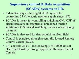
  • 1. 1 Supervisory control & Data Acquisition (SCADA) systems on I.R. • Indian Railways is having SCADA system for controlling 25 kV electric traction supply since 1976. • SCADA is meant for controlling switching ON / OFF of circuit breakers, interrupters at unmanned traction substations (TSSs) and switching stations located along the track. • SCADA is also used for data acquisition from field. • Control is exercised through a centrally located Remote Control Center (RCC). • I.R. controls 25 kV Traction Supply of 17000 kms of electrified territory through approx 53 Remote Control Centers
  • 2. 2 Modem Modem Main Communication Processor Hot Standby Communication Processor 1a 10/100 MBPS TCP/IP LAN Modem Modem 1b Main SCADA Server with HDS Hot Standby SCADA Server with HDS Operator Workstation 2a 2b Operator Workstation DOT/OFC Cable Controlled Post PANKI SSP KANPUR ( W ) SP SIRATHU FP KUNWAR SP KHAGA SSP RASULABAD TSS FAIZULLAHPUR SP FATEHPUR SSP MALWAN FP BINDKI ROAD SP KARBIGWAN SSP SARSAUL TSS CHAKERI SSP KANPUR ( E ) SP SUJATPUR SSP BHARWARI SP SAIYAD SSP MANAURI TSS BAMRAULI SP ALLAHABAD SSP NAINI FP JEONATHPUR SSP JEONATHPUR TSS AHRAURA SP CHUNAR FP PAHARA SP MIRZAPUR TSS BIROHE SP JIGNA FP UNCHDIH SP BHEERPUR TSS KARCHNA SP WAN 1 (MGS -ALD ) WAN 2 (ALD -PNK ) SCADA Equipment
  • 3. 3 Block Diagram of SCADA Man Machine Interactive (PC) Host computer (PC) Front End Processor(PC) RCC modem modem R T U modem R T U modem R T U modem R T U modem R T U modem R T U
  • 4. 4 Modern SCADA equipments e.g. RTU, MODEM & CPU
  • 5. 5 SCADA SYSTEM COMPRISES OF THE FOLLOWING • REMOTE CONTROL CENTRE (RCC) • REMOTE TERMINAL UNIT (RTU) • COMMUNICATION MEDIUM
  • 6. 6 FRONT END PROCESSOR • Two Front End Processors One Main and Other Standby( One Hot Standby ) • IF Both FEP Fails than one of MMI can be made as FEP.(Cold Standby) • Coded information from field are first received by the Modem and then Modem after digitizing gives it to FEP . • FEP software validates and receives valid data only other are rejected.
  • 7. 7 Host computer • Host computer is main SCADA Computer having overall control on all other computers. • There are Two Host computers one is main and other is Hot Standby. • Addition deletion of RTUs and other configuration application is carried out from Host Computer.
  • 8. 8 Host computer(Contd.) • Host computer processes and decode the information received and sends it to MMI for Display. • Similarly the command issued by operator from MMI first received by Host and generates data packets and send these packets to FEP for further transmission on Line
  • 9. 9 MAN MACHINE INTERFACE MMI • MMI Displays the Single Line Diagram of Traction Power supply. • The Information received from Host is displayed at relevant place on Mimic diagram. • Operator issues Telecommand on MMI which is processed through Host & FEP as explained.
  • 10. 10 MMI(Contd.) • Man Machine Interface(MMI) provides basis for all interactions between operator and SCADA system • A full graphics MMI presents the monitored parameters in an easy to understand graphical display. • It also provides features to attract attention of operator visually on occurrence of alarms.
  • 11. 11 MMI (Contd.) • System also provides three security levels for access to different operations. • a) Traction Power Controller level:- access to view and control. • b) RCC Engineer:- Access to edit configuration, add user(TPC) in addition to above. • c) Higher level:-Facility to add RCC engineer and manage user permission in addition to above two. • All actions are menu driven and prompting such that errors are minimum.
  • 12. 12 Flow diagram 1 M RTU Modem FEP PC • Command Flow diagram RCC To RTU HOST PC MMI PC Operator Analog signal digital signal
  • 13. 13 Flow diagram 2 • Command Flow diagram RTU To RCC HOST PC Operator M FEP PC MMI PC RTU M Analog signal digital signal
  • 14. 14 SOFTWARE FEATURES (Telecommands) • Execution of telecommands • Time synchronisation of RTU and RCC • Test procedure to check communication health • “OFF” Scanning of RTUs to isolate defective RTUs. • Downloading of parameters from RCC to RTU • Diagnostic of RTU’s from RCC upto card level
  • 15. 15 • Interlocking of devices to avoid undesirable operations. • Locked out signals for various devices. • Printing of data & Reports • Monitoring of Power block like alarms and their logging. • Audible Alarm. SOFTWARE FEATURES (configuration)
  • 16. 16 SOFTWARE FEATURES (configuration) • Maximum Demand(MD) monitoring. • Under voltage range setting at SP’ RTUs for tripping under extended feel conditions. • Auto Fault Localisation .-software prompts TPC to start AFL • Picture editor- To add/delete device etc.
  • 17. 17 REMOTE TERMINAL UNIT • RTU is common interface between Field devices and RCC • RTU is Microprocessor based logic system. • Accepts digital and analog input signals from field • Receives control command from RCC. • Replies information asked by RCC.
  • 18. 18 RTU Architectural Details • Power Supply Unit • CPU • Digital Input Module (DIM) • Digital Output Module (DOM) • Analog Input Module (AIM) • Signal Conditioning Card
  • 19. 19 RTU Architectural Details(Contd.) • Modem-For Modulation and Demodulation • Contactors- To extend 110 supply to field devices for operation. • Transducers: For Voltage , Current and Power factor measurement
  • 20. 20 BASIC BLOCK DIAGRAM OF RTU • Battery 240 V AC CPU DIT DOT AIT Power supply unit Modem Trans- ducers Tx Rx C O N T A C T O R S.C.Card input from Field devices
  • 21. 21 RTU FUNCTIONAL DETAIL CPU • CPU: Microprocessor based logic System coupled with firmware Programming performs as a brain of RTU • 16 bit device • 20 MHz Speed • Built in RAM/Backup EPROM-128 KB • Watchdog Timer
  • 22. 22 Digital Input Module(DIM) • Digital Input module provide Input point for Status Information to CPU. • This provides bistate field devices status to CPU of RTU. • Digital Input module accepts input from field via Signal conditioning card
  • 23. 23 Digital Output Module(DOM) • Digital Output module receives Output from CPU. • The output signal from DOM derives a interposing relay/Opto-coupler which in turn extend 110 dc supply to contactor • The Contactor extend supply to Field device for operation. • Each device has separate contactor for each open and close operation
  • 24. 24 Analog Input Module(AIM) • Transducers receives analog signals from CTs /PTs. • Transducers convert them to proportional digital values. • These values are fed to Analog Input module(AIT) and then to CPU. • CPU transmits them to RCC as per protocol
  • 25. 25 STATUS &TELESIGNAL FLOW DIAGRAM T DIM Mod em Mod em FEP Host MMI TPC RCC CPU • . SC card Field device RTU
  • 26. 26 TELEMETRY FLOW DIAGRAM . CT/ PT Transduc er AIM CPU Mod em Mod em FEP Host MMI TPC Field RCC RTU
  • 27. 27 WHAT IS A PROTOCOL ? • What is a Communication Protocol ?- A defined rules and regulations for Communication between two Intelligent devices. i.e. between RCC and RTU. • Why a standard Protocol? To ensure interchangeability of RTU of different vendors. • Based on International Standard IEC-870-5 Standard Communication Protocol is based on IEC-870-5 .
  • 28. 28 Equipment layout of standard system at RCC
  • 29. 29 29 Maintenance of Remote Control Centre / RTU Remote Control Centre • Monthly Schedule Dust cleaning Level checking (RCC & POST) • Half Yearly Schedule Dust cleaning Level checking (RCC & POST) Voltage / Current checking
  • 30. 30 30 Maintenance of Remote Control Centre / RTU (Contd.) Remote Control Centre • Yearly Schedule Dust cleaning Slot & contact cleaning with contact cleaner Level checking (RCC & POST) Voltage / Current checking
  • 31. 31 31 Maintenance of Remote Control Centre / RTU (Contd.) Remote Terminal Unit • Half Yearly Schedule Dust cleaning Level checking (RCC & POST) Voltage / Current checking • Yearly Schedule Repeat half yearly schedule Slot & contact cleaning with contact cleaner
  • 32. 32 32 Maintenance of Remote Control Centre / RTU (Contd.) Remote Terminal Unit • Four Yearly Schedule Dust cleaning Slot & contact cleaning with contact cleaner Remove all cards/module clean & refix Level checking (RCC & POST) Voltage / Current checking
  • 33. 33 Traction Power Control (TPC) Organization RCC • Heart of Control System • Manned 365x24 • No operation in system without TPC approval Traction Power Controller • Contact with power supply authority • Liasion with section controller • Breakdown. Co-ordination & control • Record Maintenance, Log Books, Shift registers
  • 34. 34 Traction Power Control Organization (Contd.) • Isolation of Faulty Section. • Faulty Section to be kept isolated. • Advice to Section Controller. • Information to Traction Staff. • Action to Rectify Fault. • Monitoring faults on Railway Equipments, Grid, Power supply. 34
  • 35. 35 Emergency Arrangement • T&P Spares in TOWER WAGON/ TRUCK/ART • Vehicle Truck/TW/Jeep/Wiring train • Emergency Stores • Emergency staff • Emergency telephone • Role of TPC 35
  • 36. 36 Co-Ordination with Operating & other departments OPERATING  Request for Power Blocks from traffic department.  Tower wagon movement control. ENGINEERING  Power block for P Way maintenance.  Bonds maintenance  Maintenance of overhead structures. 36
  • 37. 37 Co-Ordination with Operating & other departments (Contd.) S&T • TPC/ SCADA/ Emergency Telephoning Circuit operation • Protection of signal structures (Earthing/Bonding) • AT supply to CLS panel. • BT/RC Circuit 37
  • 38. 38 Liaison with Power Supply Authorities • Agreement between Railway Authority & Supply Authority. • Periodic meeting meetings at different level. • Reliability of supply & maintenance of voltage frequency. • Treated as essential load • Frequent Power Supply interruption. • Power line crossing maintenance issues. 38
  • 39. 39 Liaison with Power Supply Authorities (Contd.) • Supply failure actions • Tariff revision issues • Load revision issues • Reliability of SEB protection system • Maximum demand management. 39
  • 40. 40 Safety Precautions for Electric Section (Contd.) Rules For S&T Installation • Effect of OHE on S&T Equipment. • Precaution in Event of Breakage of wires. • Working on Signal Post & Fittings. • Precaution against built up of Potential due to Return Current in Rails. • Induction Potential in Metallic. 40
  • 41. 41 Safety Precautions for Electric Section (Contd.) Over-Dimensioned Consignment • Precautions for movement of ODCs. • Power Block for movement of ODC. Other Precautions • Hoarding Boards. • Rubber Tyred Vehicles on Railway Wagons • Loading & Unloading of Petroleum Product 41
  • 42. 42 Safety Precautions for Electric Section (Contd.) Rules Applicable to P-Way staff. • Continuity of Track. • Permanent Way Tools. • Track-Circuited Rails. • Care in Handling Pipes etc. • Steel Measuring Tapes not to be used. • Traction Structure Foundation. 42
  • 43. 43 Safety Precautions for Electric Section Watering of carriages • Watering Section • Controlling Switches • Sequence of Interlocking & Operation. • Authorized to open Interrupters & Isolators. • Custody of Keys, Watering of Carriage. • Restoration of supply. 43
  • 44. 44 TRACTION STORES & ITS ACCOUNTAL Main Central Depot • Sub Depot Store (OHE & PSI Depots) • Emergency Store • Store at Tower Wagon/Tuck • T&P/Spares/Consumable • Ledgers maintained at sub depots
  • 45. 45 TRACTION STORES & ITS ACCOUNTAL • Standardization of stores • Stock item & NS items • Stocking on basis of AAC • Stock items directly by stores department • Special requisitions. • Liasion with stores department
  • 46. 46 TRACTION STORES & ITS ACCOUNTAL • Non stock procurements on basis of demand • Preparation of indents • Requisition to stores • Local purchase • PAC & Imported items
  • 47. 47 TRACTION STORS & ITS ACCOUNTAL • Custody & accountal • Inspection of stores • Inventories of dead stock • Accountal & disposal of scrap etc. • Condemnation & verification of stock • Stores computerization
  • 48. 48 Regulation for Electrical Crossing of Railway tracks. General • Approval of Works by Railway. • Compliance with Indian Electricity Act • Compliance with Indian Standard Spec. • Protection of Communication Line. • Maintenance of Crossing, Defects & Failure. 48
  • 49. 49 Regulation for Electrical Crossing of Railway tracks. (Contd.) 49 Item Remarks Angle of Crossing  At right angle to the railway track.  In special cases, a deviation of upto 30°.  Deviations < 30° – Authorized by EIG/CEE. Crossing span  Crossing span – 300 m or to 80% of the normal span, whichever is less. Wind pressure  Maxm wind pressure – As prescribed in IS:802 (Part-1)- 1977 for load and permissible stresses. Temperature  Maxm & Minm temperatures for design of conductors & other wires – As prescribed in IS:802 (Part-1, Clause-4)
  • 50. 50 Regulation for Electrical Crossing of Railway tracks. (Contd.) Overhead Line Crossings • Minimum clearances between crossing conductors & any Railway structure. • Minimum vertical clearance between power line crossing. • Clearance bet. Power & communication line. • Insulators & Guarding. 50
  • 51. 51 Regulation for Electrical Crossing of Railway tracks. (Contd.) Overhead Line Crossings • Anti-Climbing device & warning notice. • Protection from moving road vehicles. • Communication line. • Earthing. • Fire Hazards. 51