Download to read offline


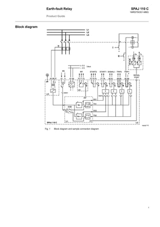


The document provides information on the SPAJ 110 C earth-fault relay: 1) The relay has two protection stages, a low-set and high-set neutral overcurrent stage, and can be used for primary or back-up earth-fault protection on power systems. 2) Key features include definite time and inverse time operation for the low-set stage, self-diagnostics, serial communication interface, and flexible configuration of protection and output functions. 3) The relay measures earth fault current via current transformers and provides trip and alarm outputs when fault thresholds are exceeded.


