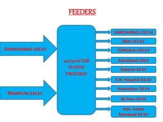
1. The document describes a 220kV substation in Firozabad, including its layout and main equipment.
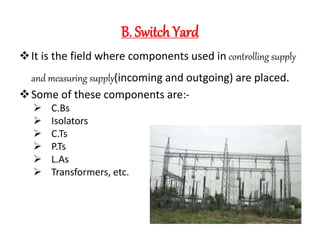
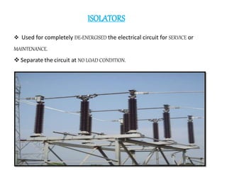
2. The substation has a panel section containing control and relay panels, and a switchyard section with components like circuit breakers, isolators, transformers and lightning arrestors.
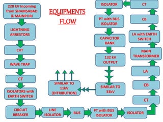
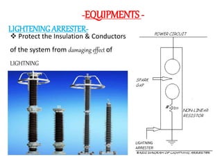
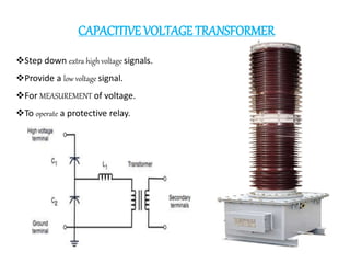
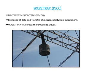
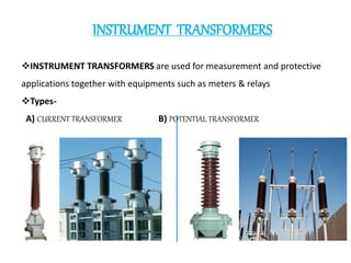
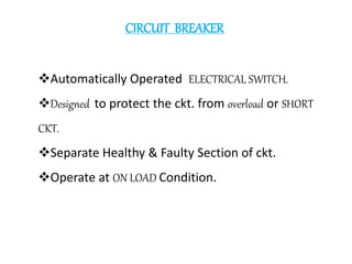
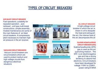
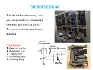
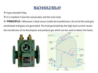
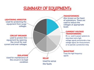
3. Key equipment discussed include transformers, current and voltage transformers, circuit breakers, isolators, lightning arrestors, wave traps and protective relays like Buchholz relays.