Downloaded 3,712 times
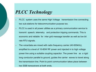
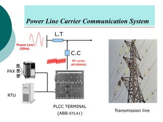
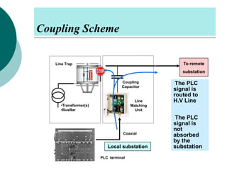

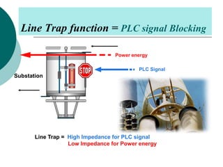
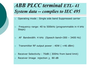
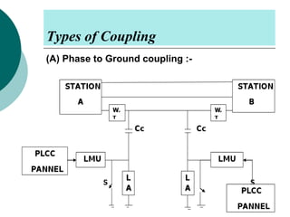
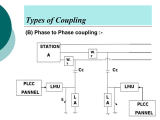
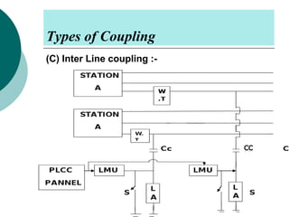
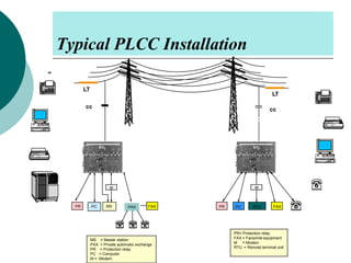


PLCC uses high voltage transmission lines to transmit speech, telemetry, and protection commands between substations in a cost effective and reliable way. The signals are modulated onto a carrier frequency between 40-500kHz and injected onto the line through coupling capacitors. Line traps allow the signals to pass through but prevent them from entering the substations. The technology provides communication without additional wiring by using the existing power infrastructure.


