Downloaded 31 times
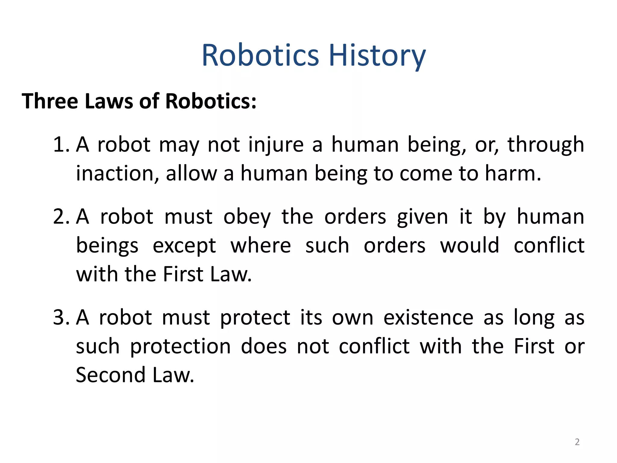
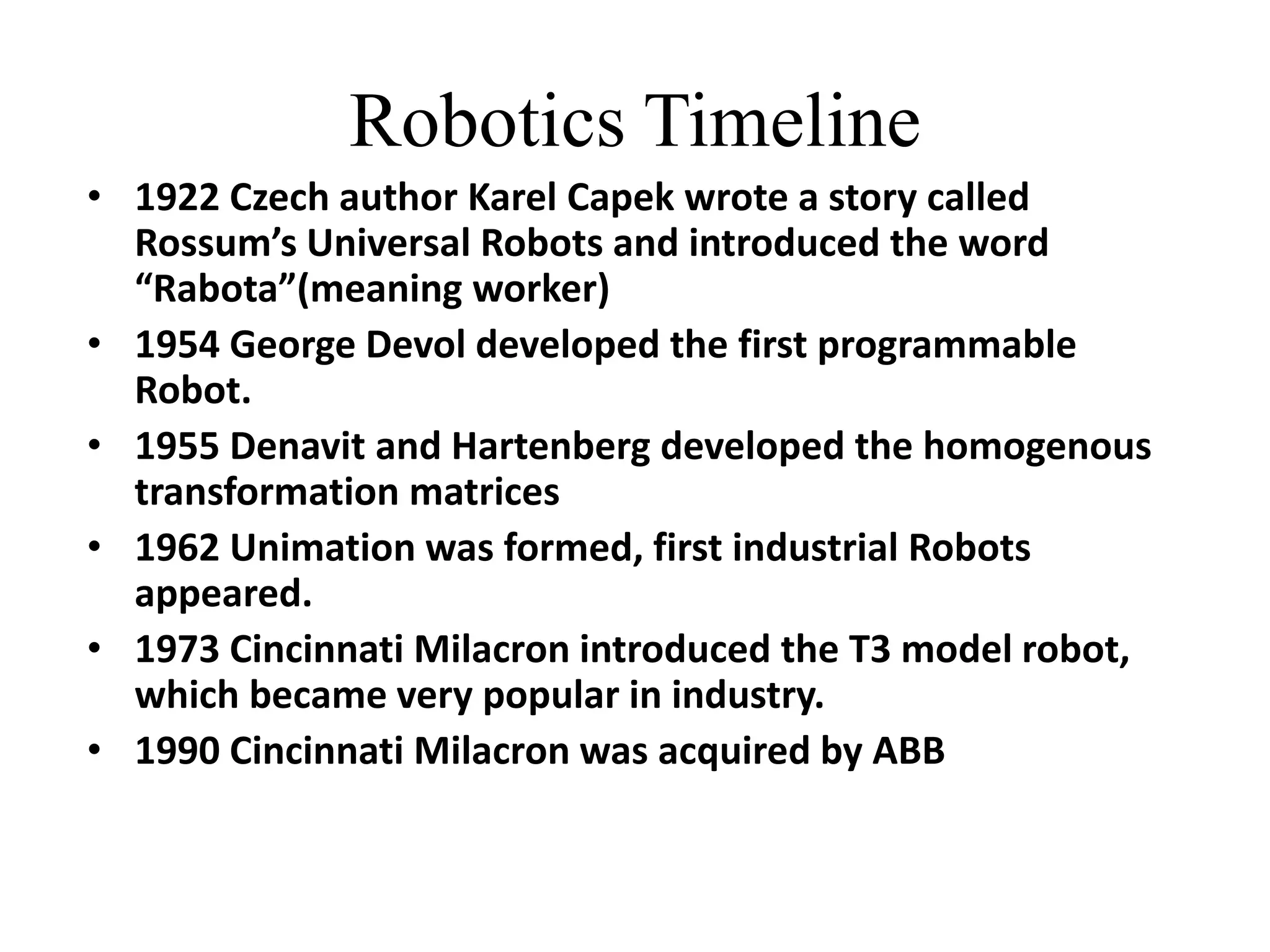
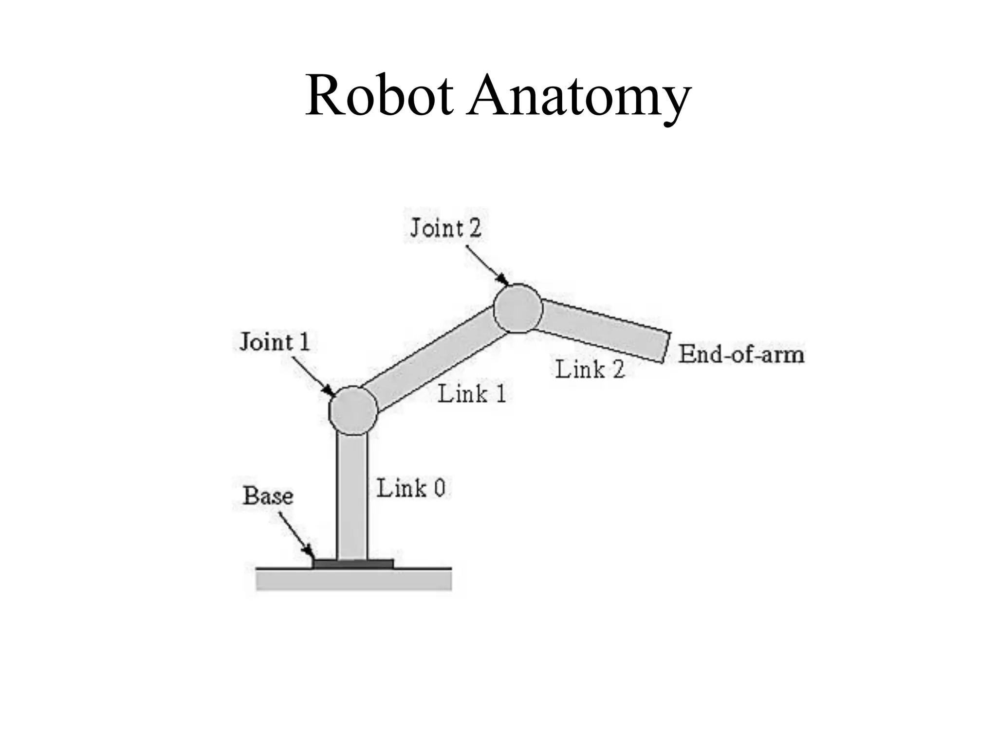
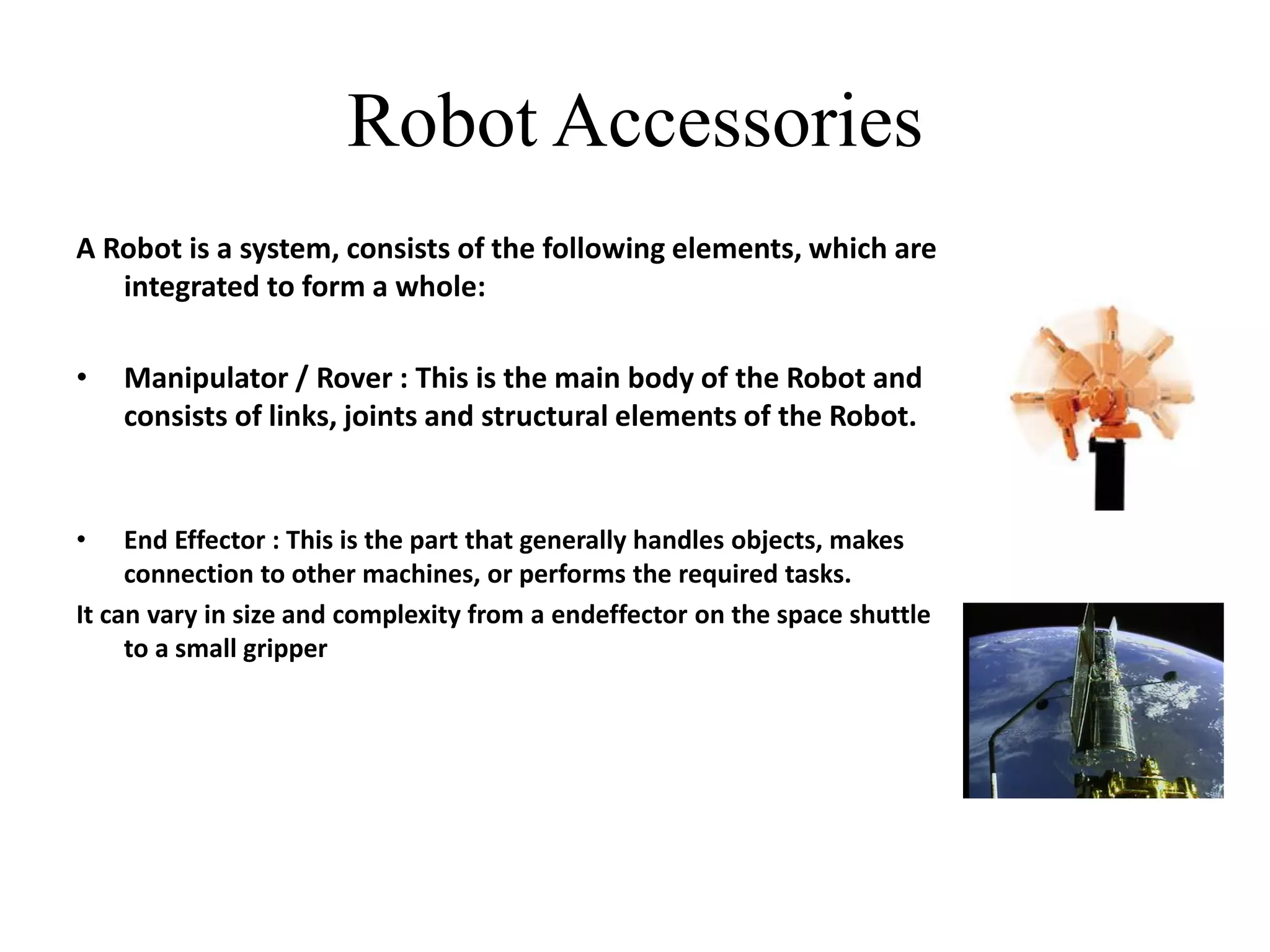
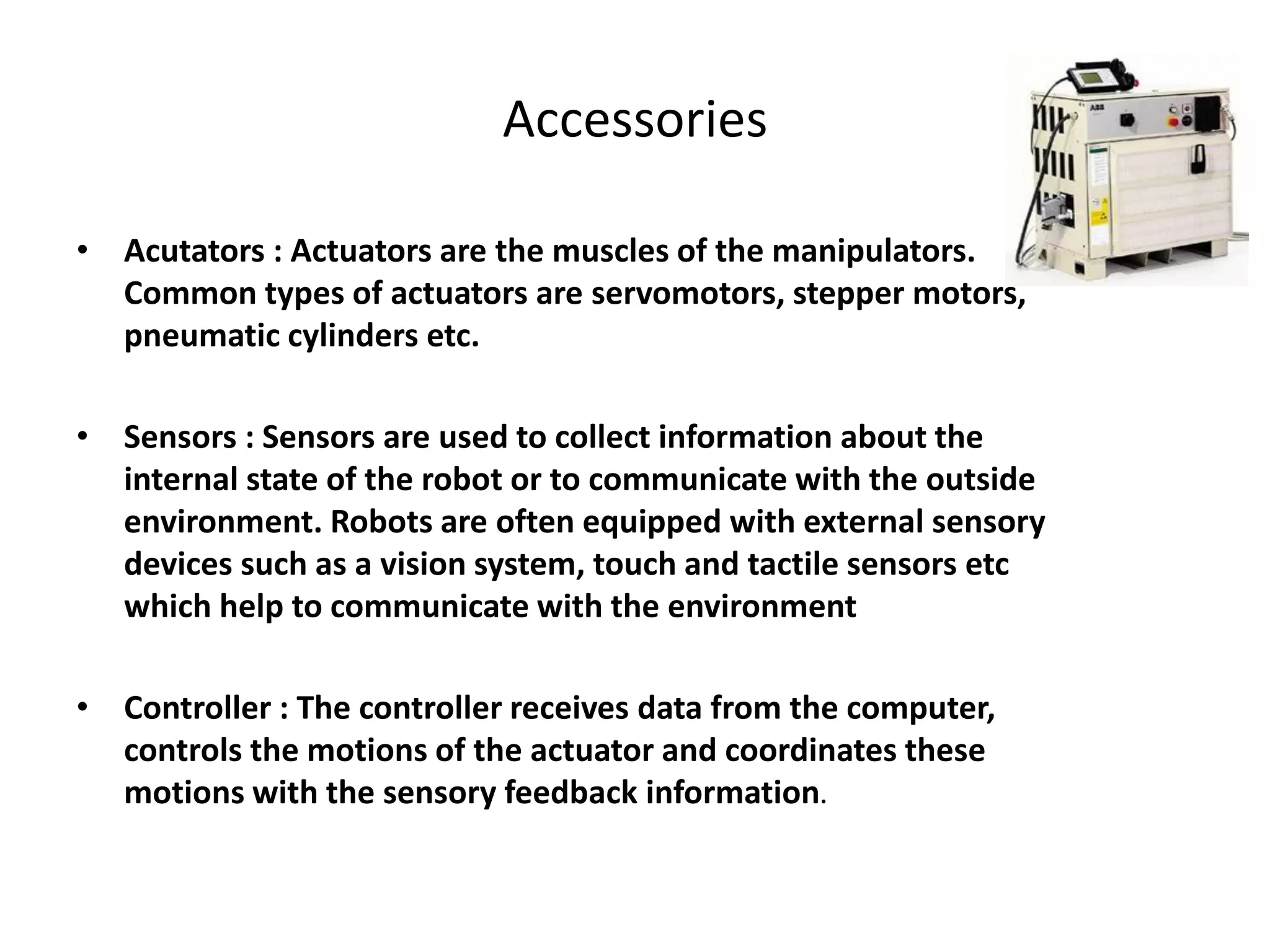
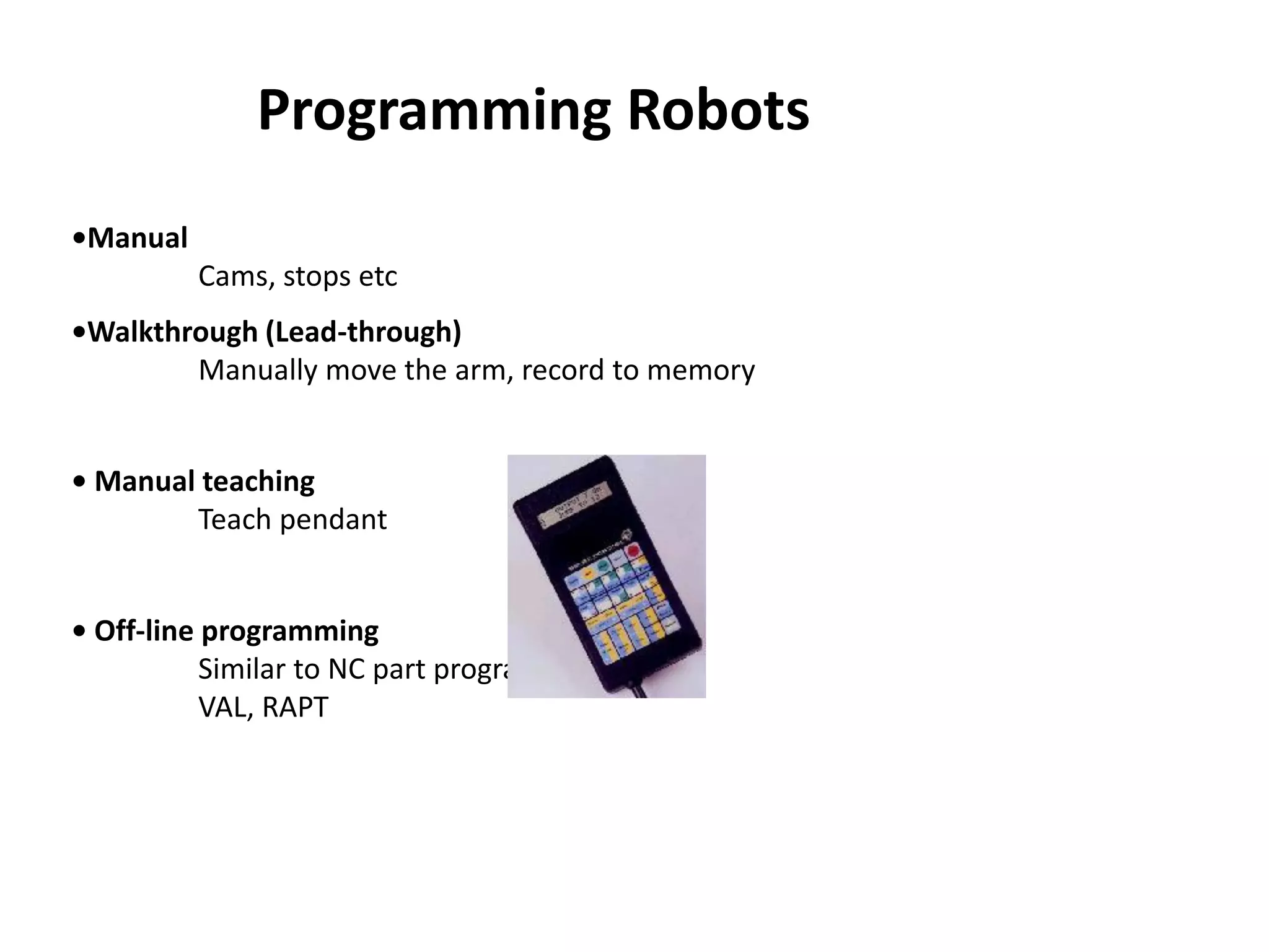
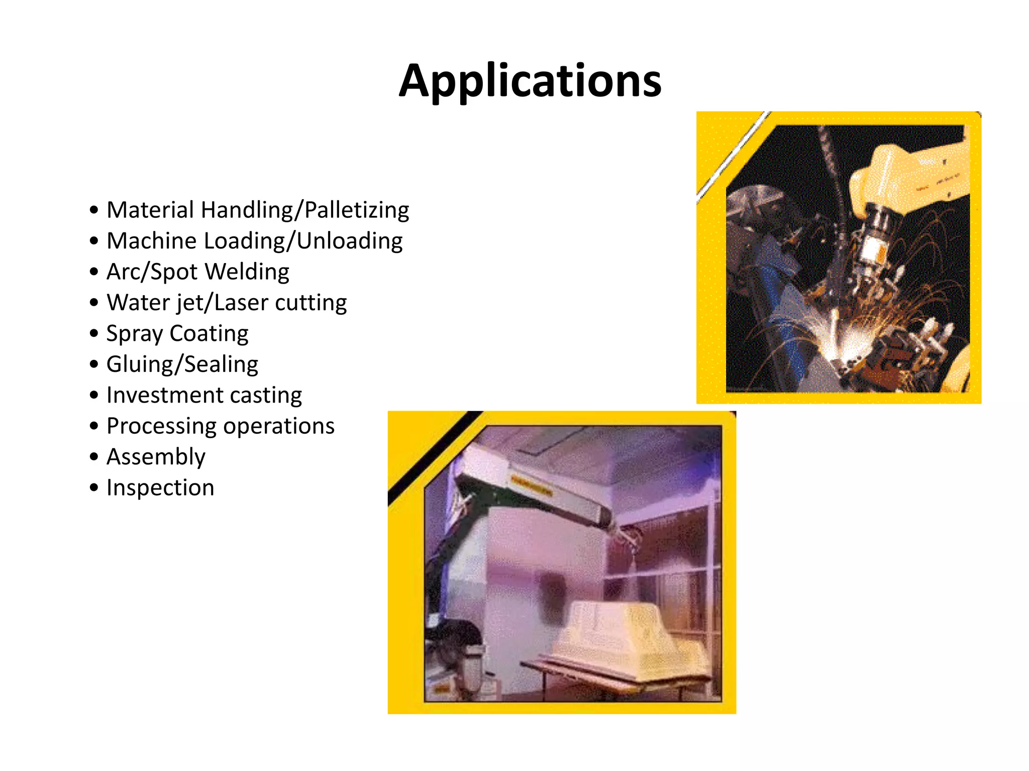
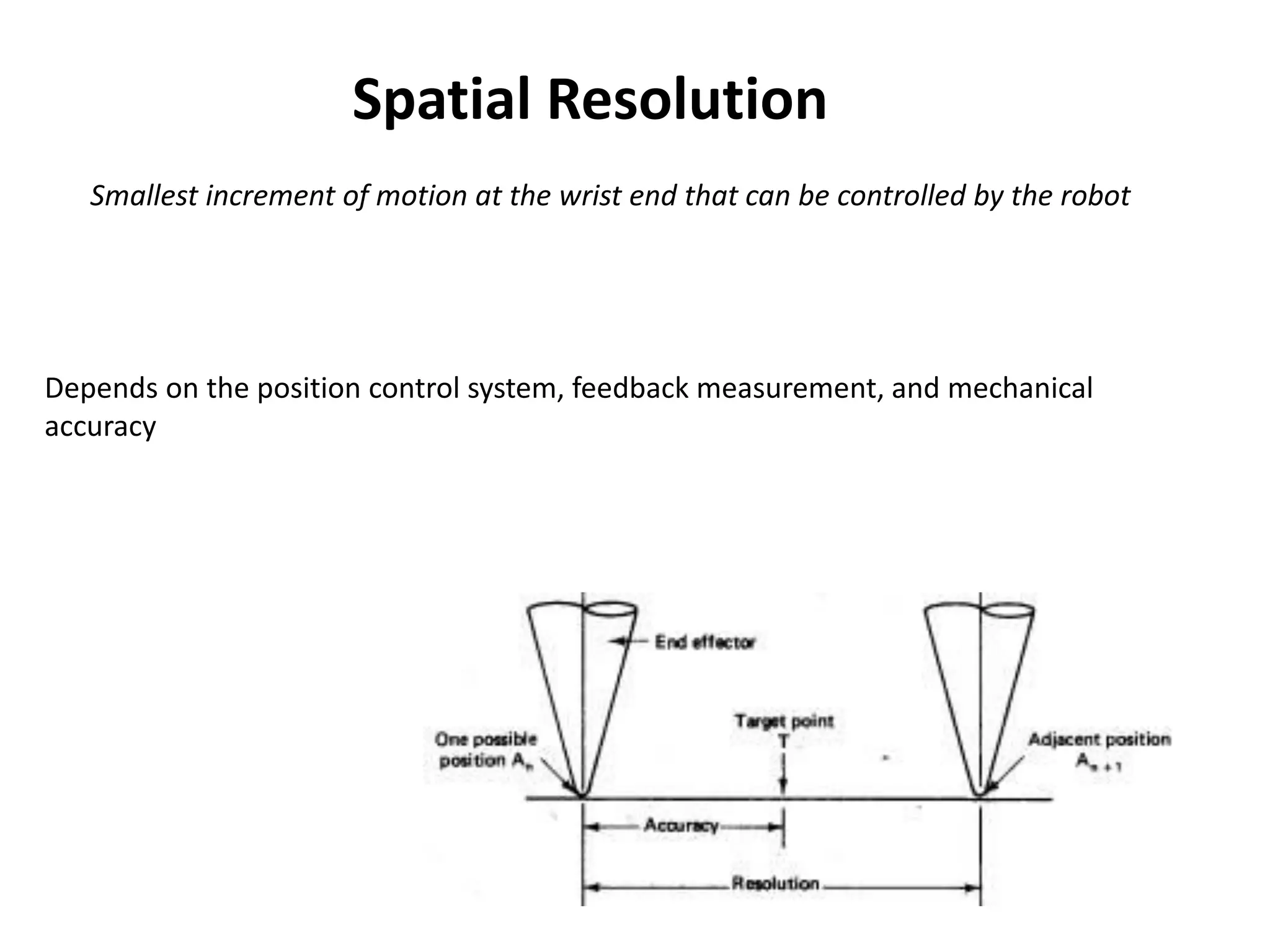
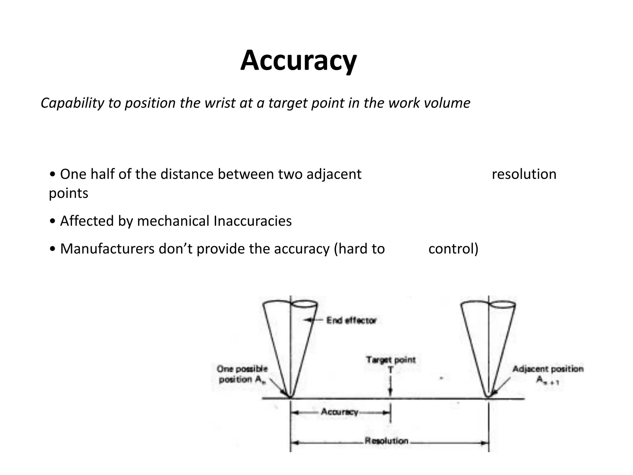
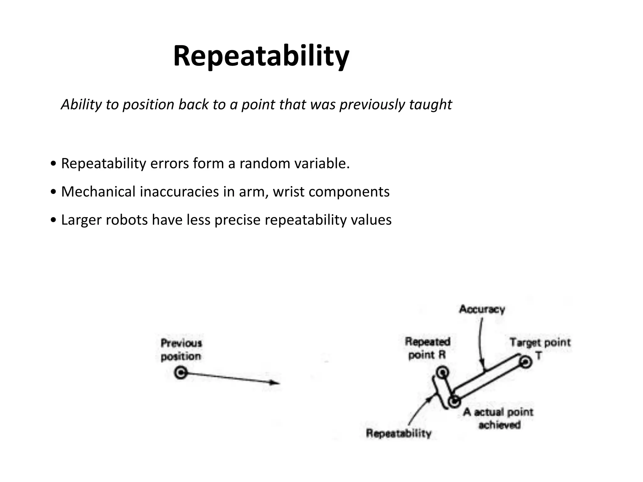


This document provides an overview of robot fundamentals including: - The three laws of robotics which govern robot behavior to protect humans. - A timeline of major developments in robotics from the 1920s to the 1990s. - The main components of an industrial robot including the manipulator, end effector, drive source, control system, and sensors. - Common robot programming methods like manual teaching, walkthrough, and offline programming. - Applications of industrial robots in areas like materials handling, machine loading, welding, and assembly. - Performance specifications that characterize robots like work volume, speed, accuracy, load capacity, and repeatability.
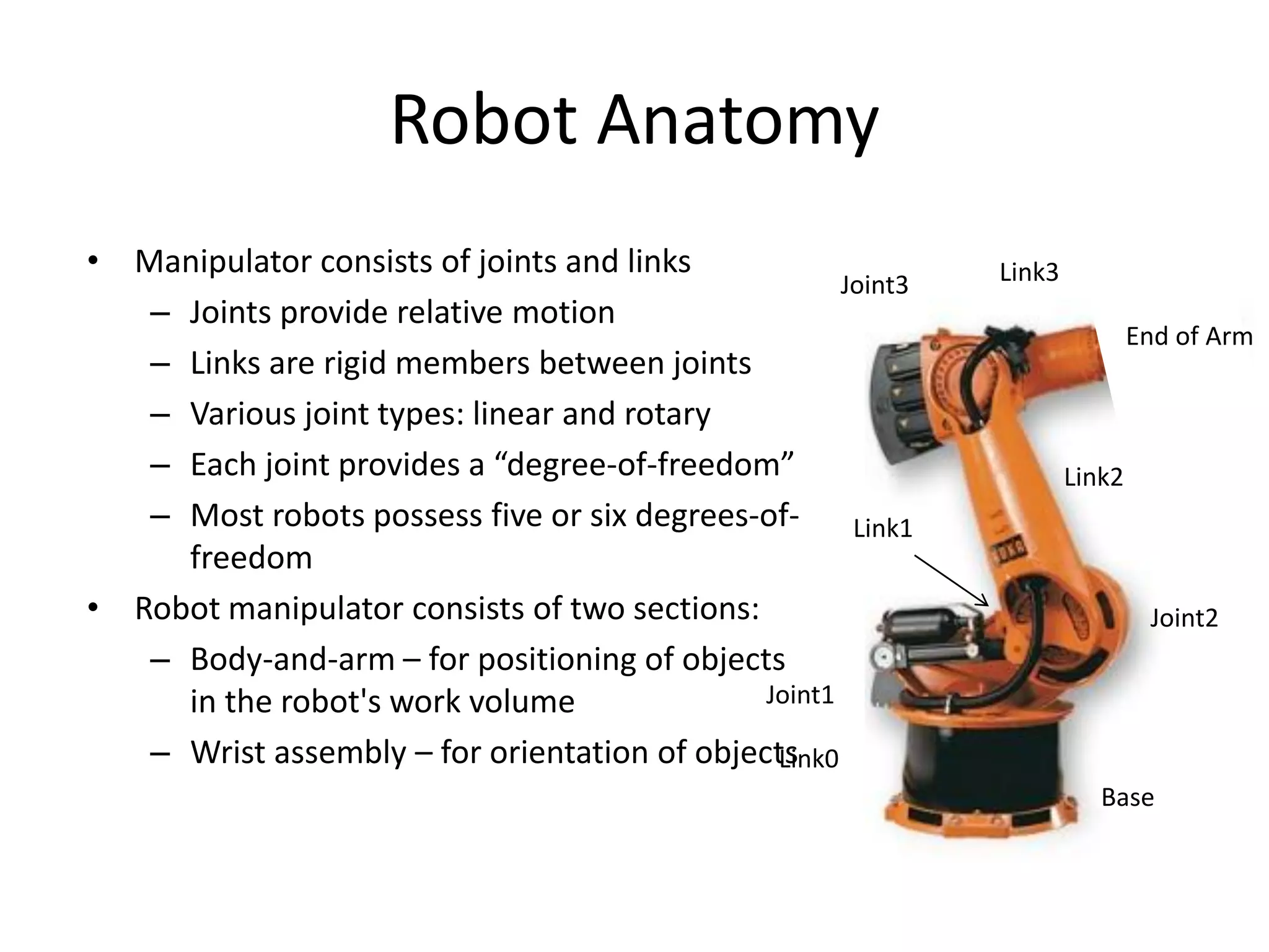
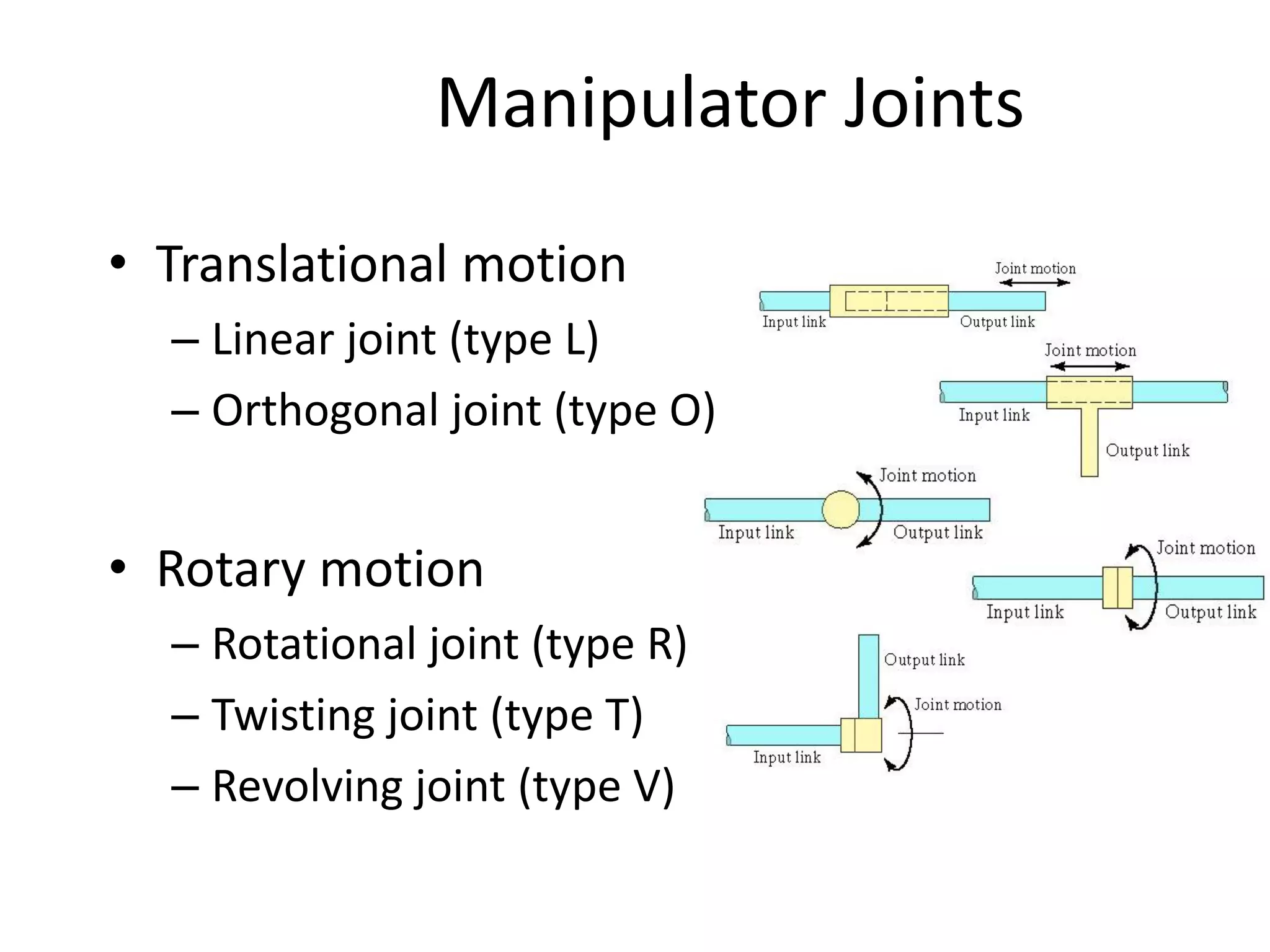
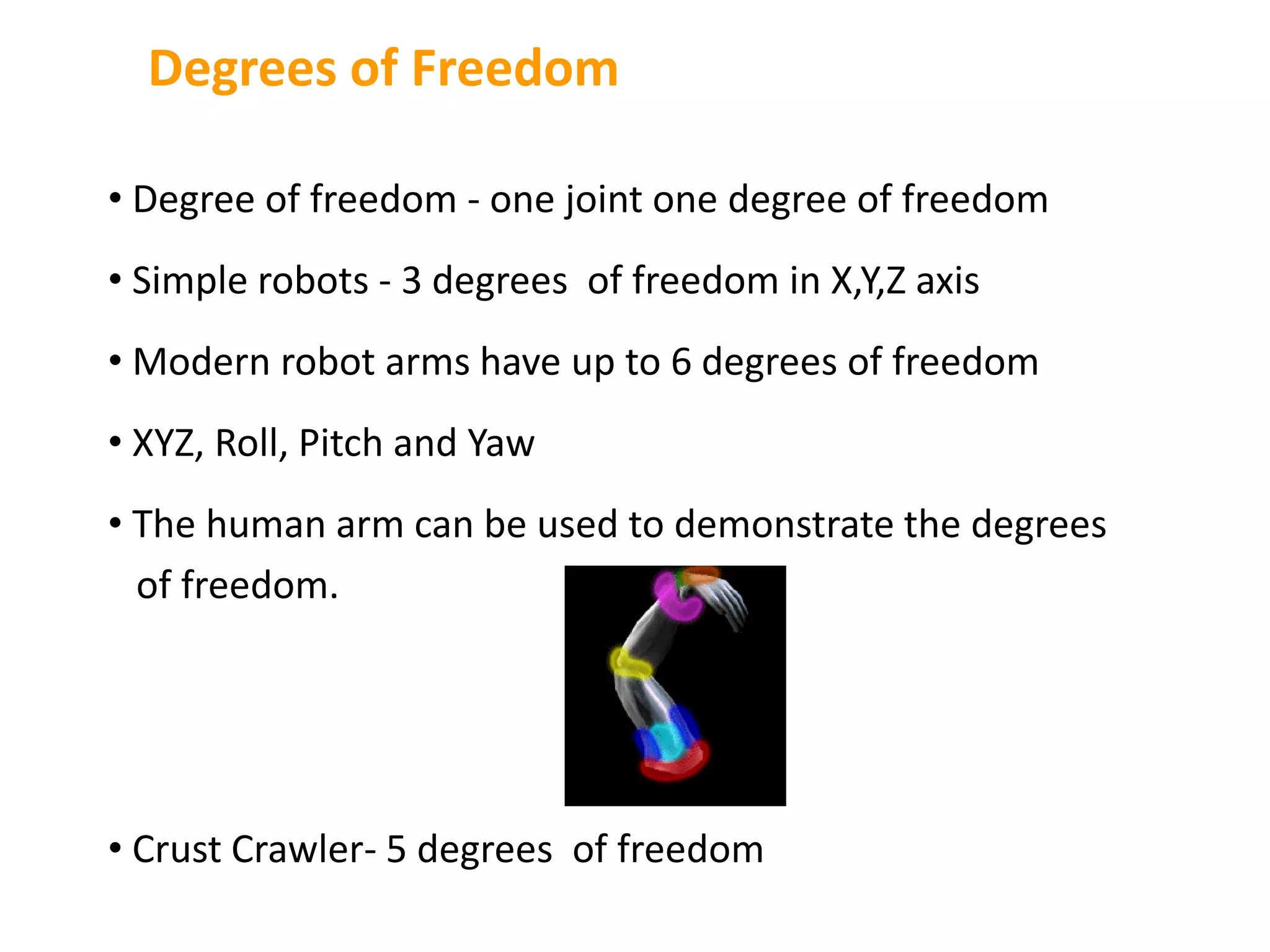
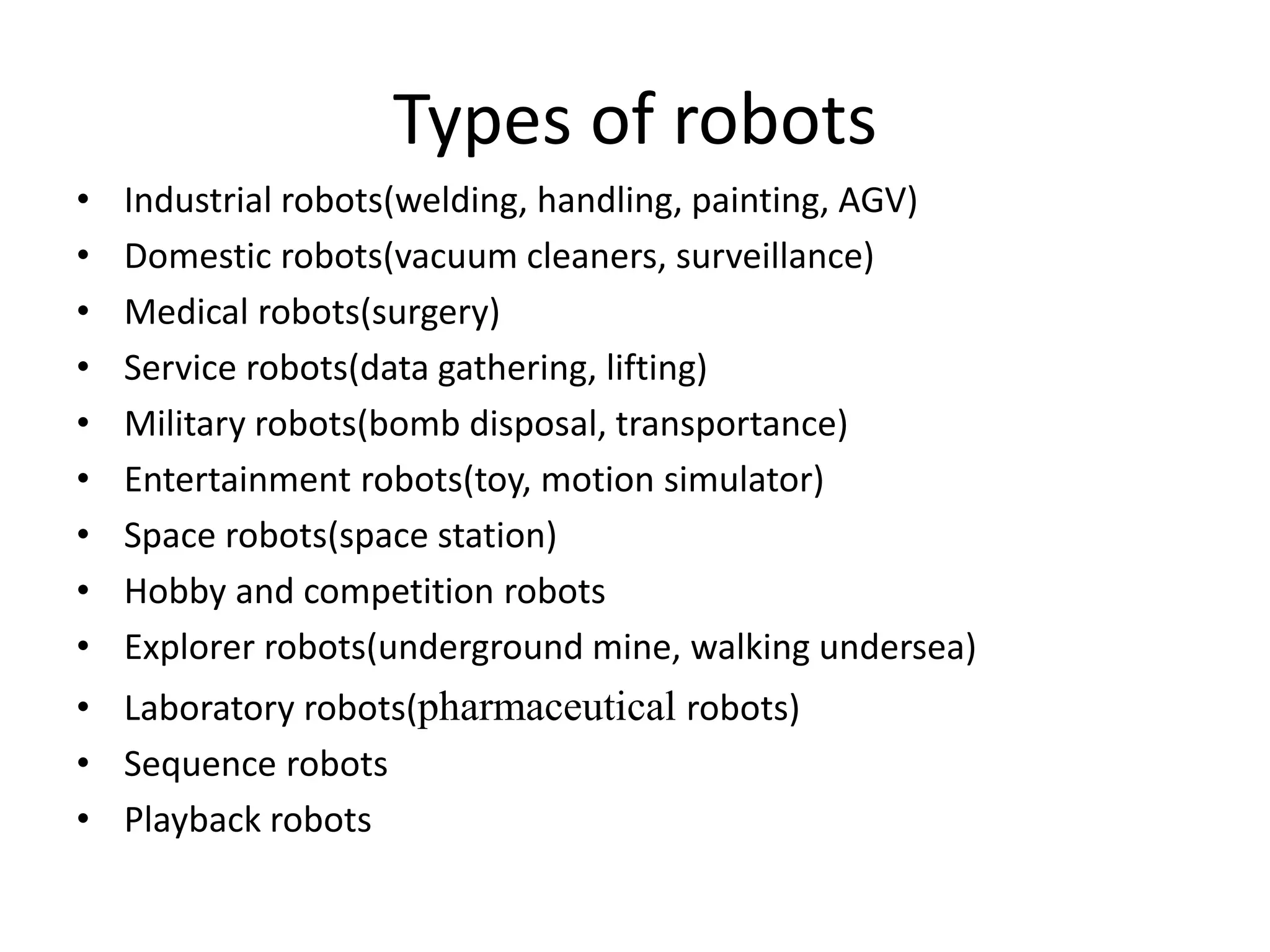
Introduction to robotics, history, laws, anatomy, functions, and classification of robots including actuators and controls.
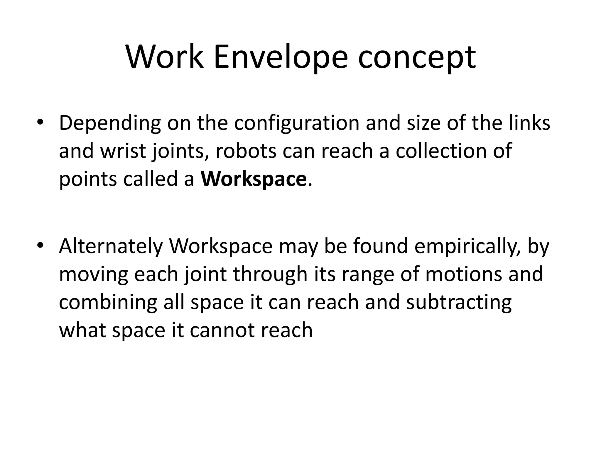
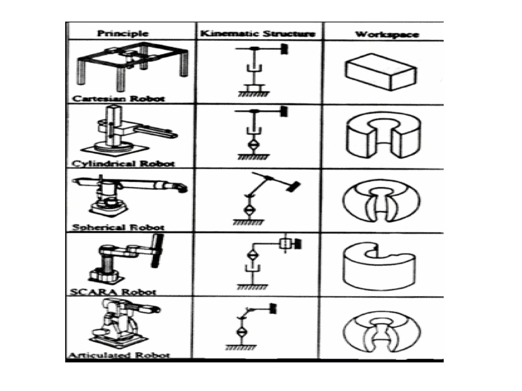
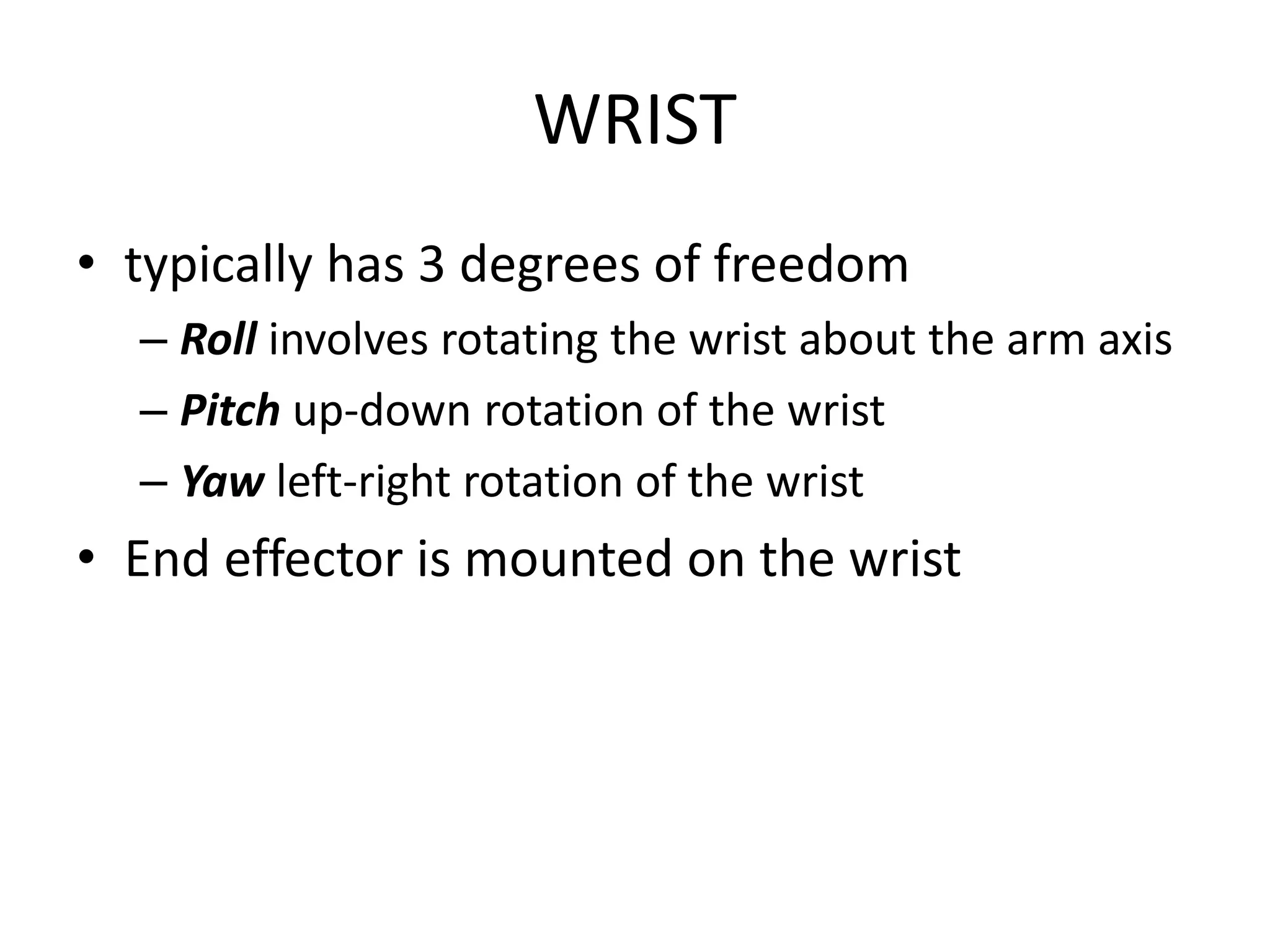
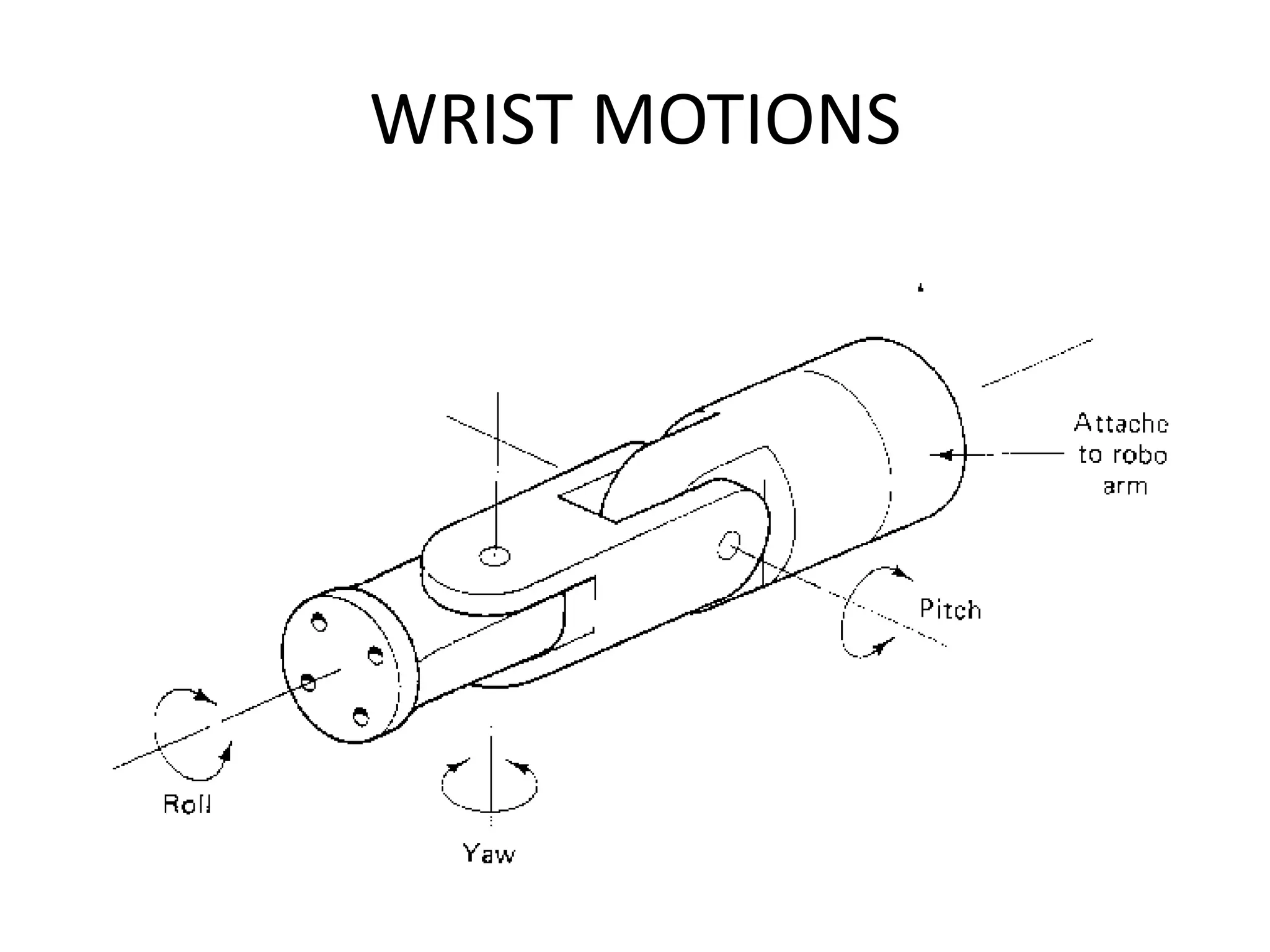
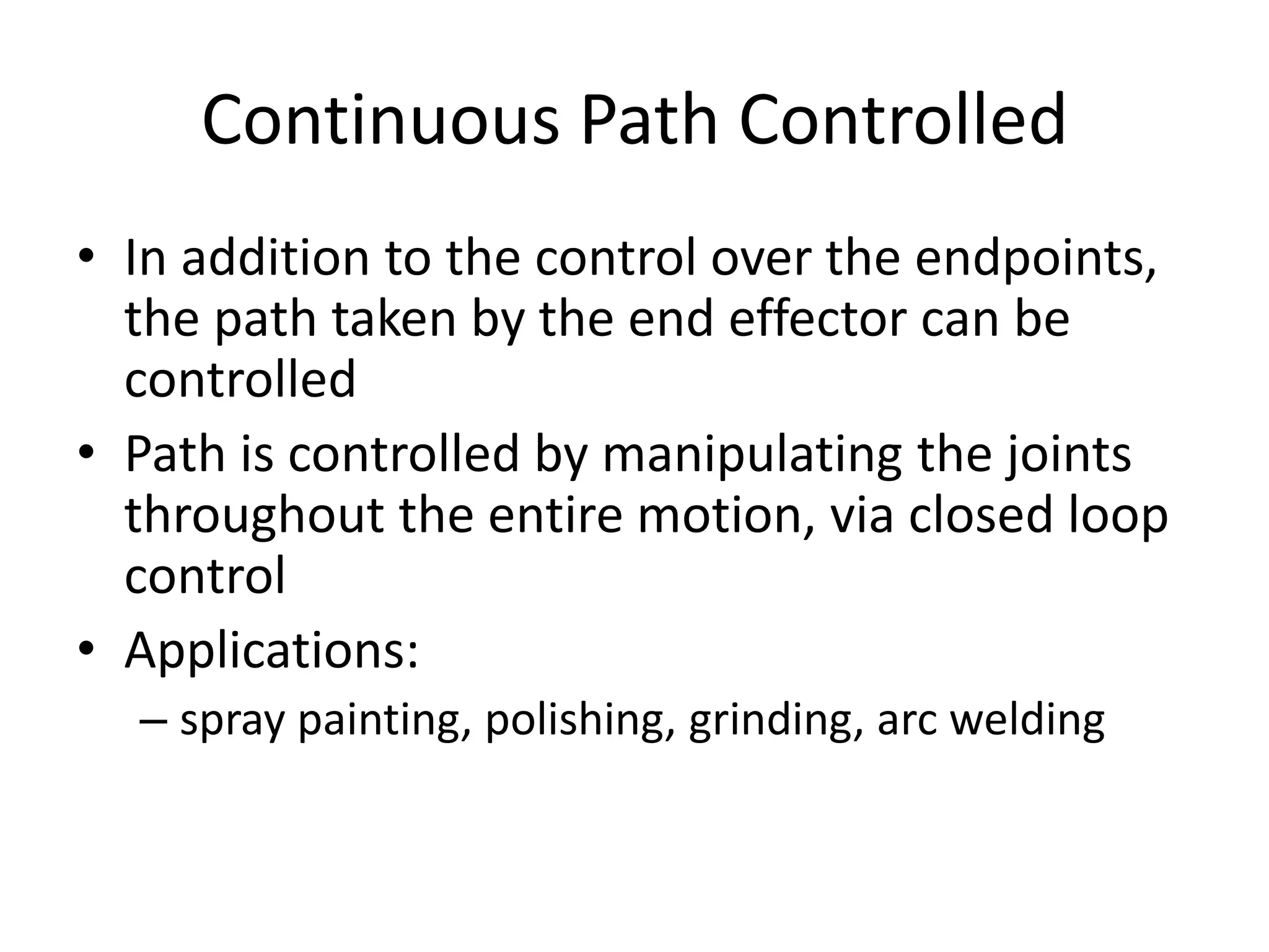
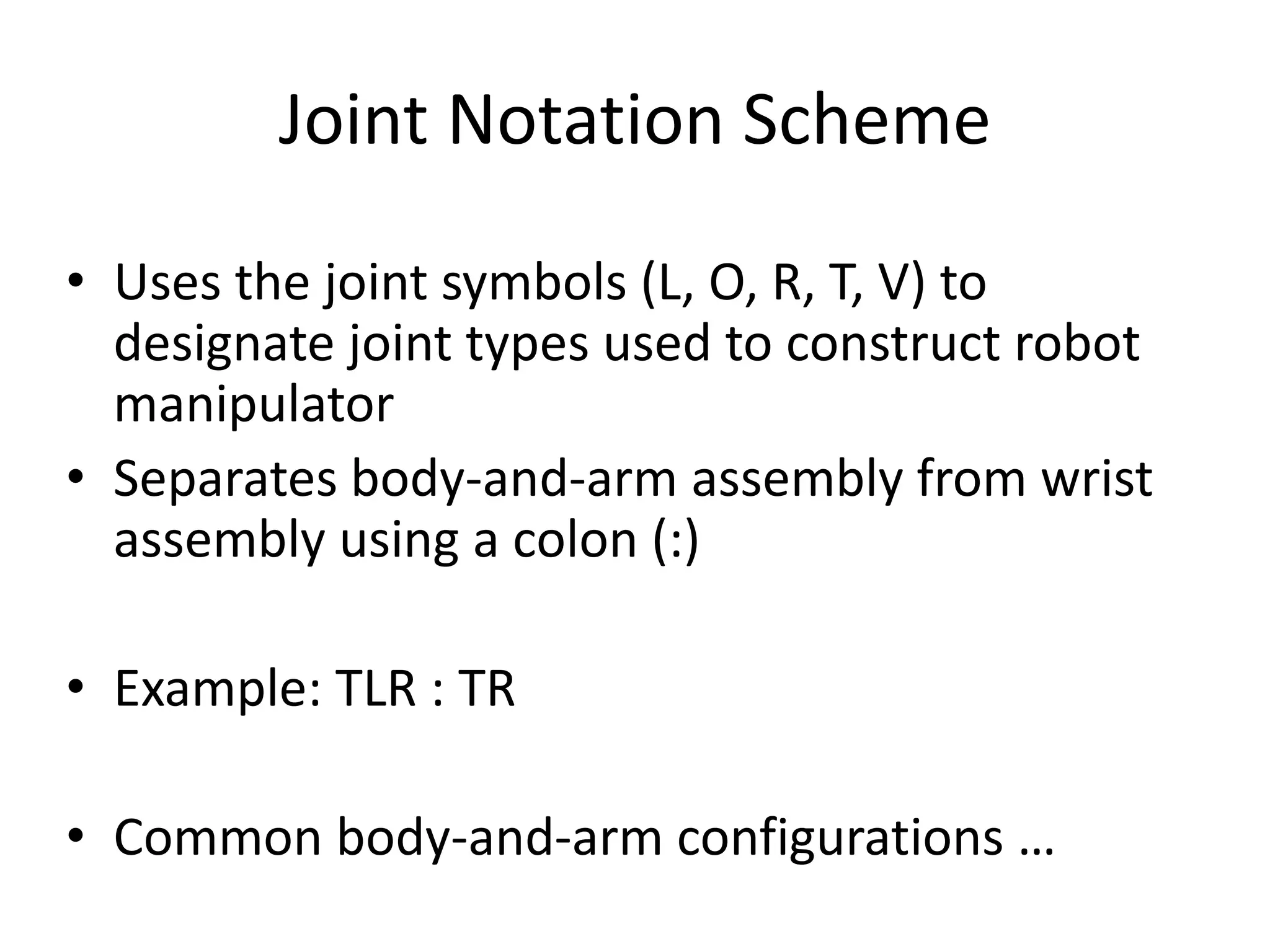
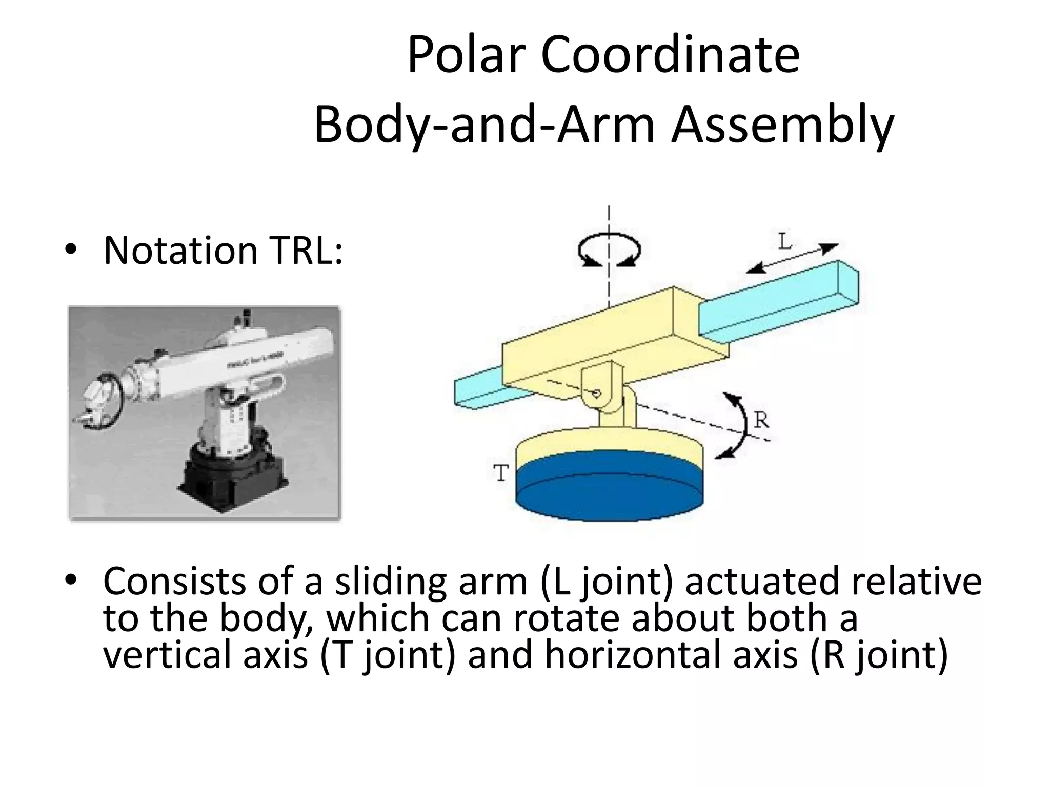
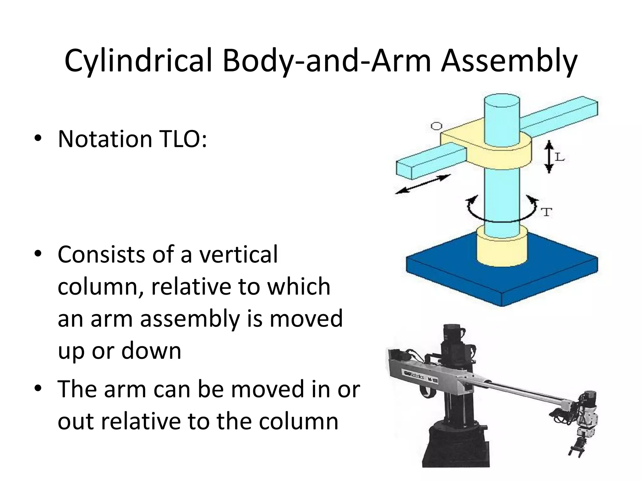
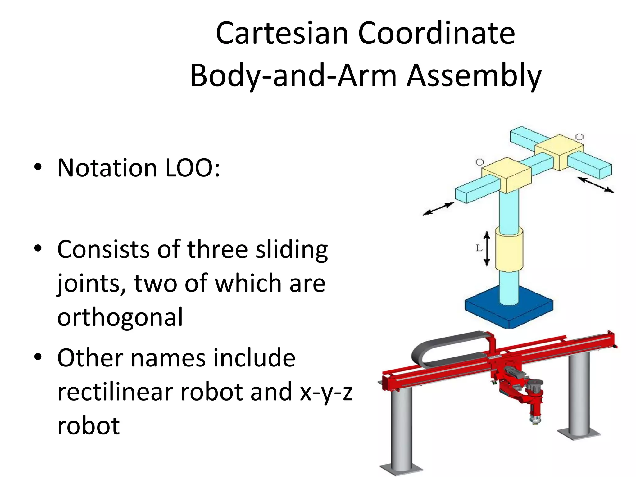
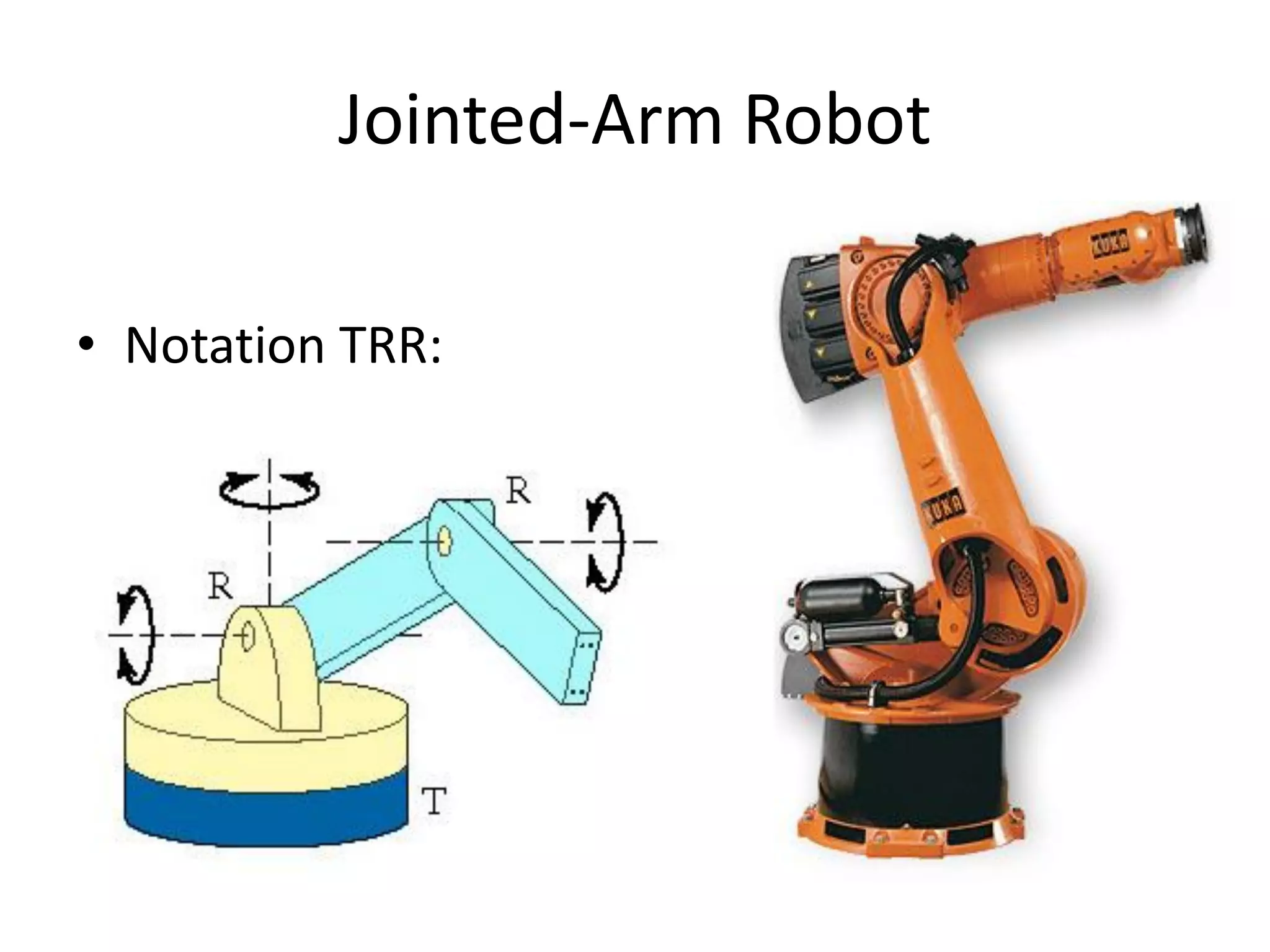
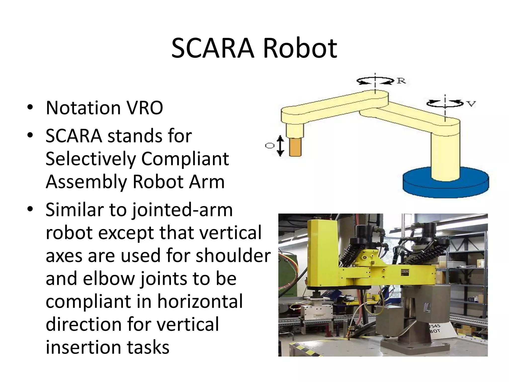
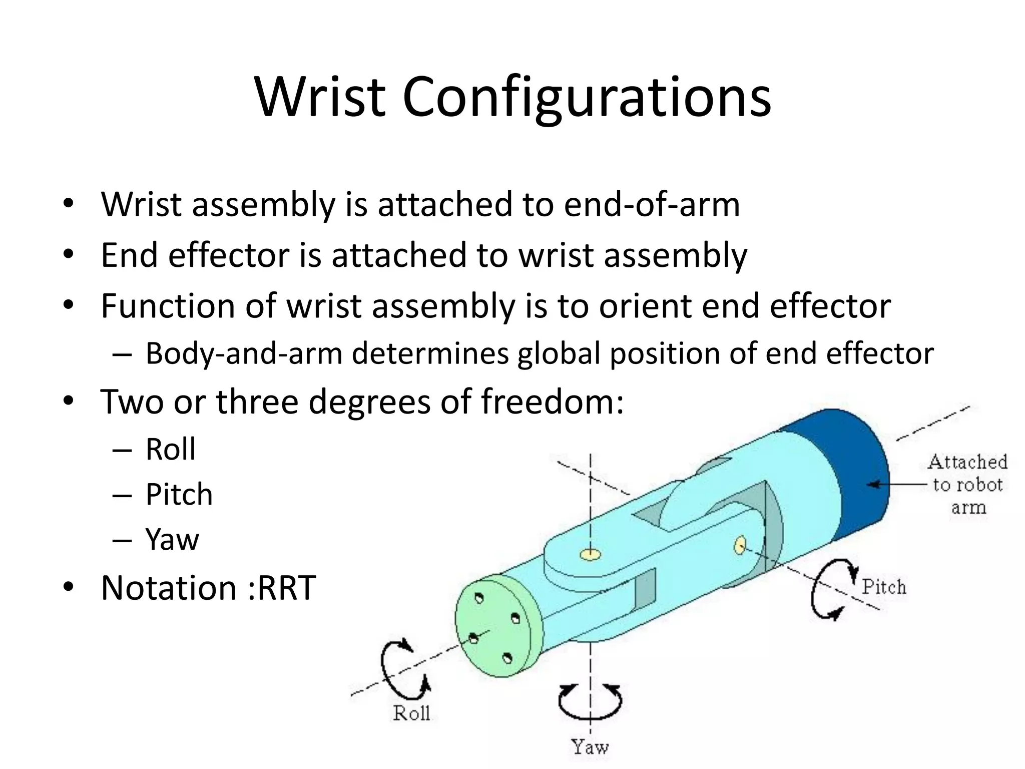
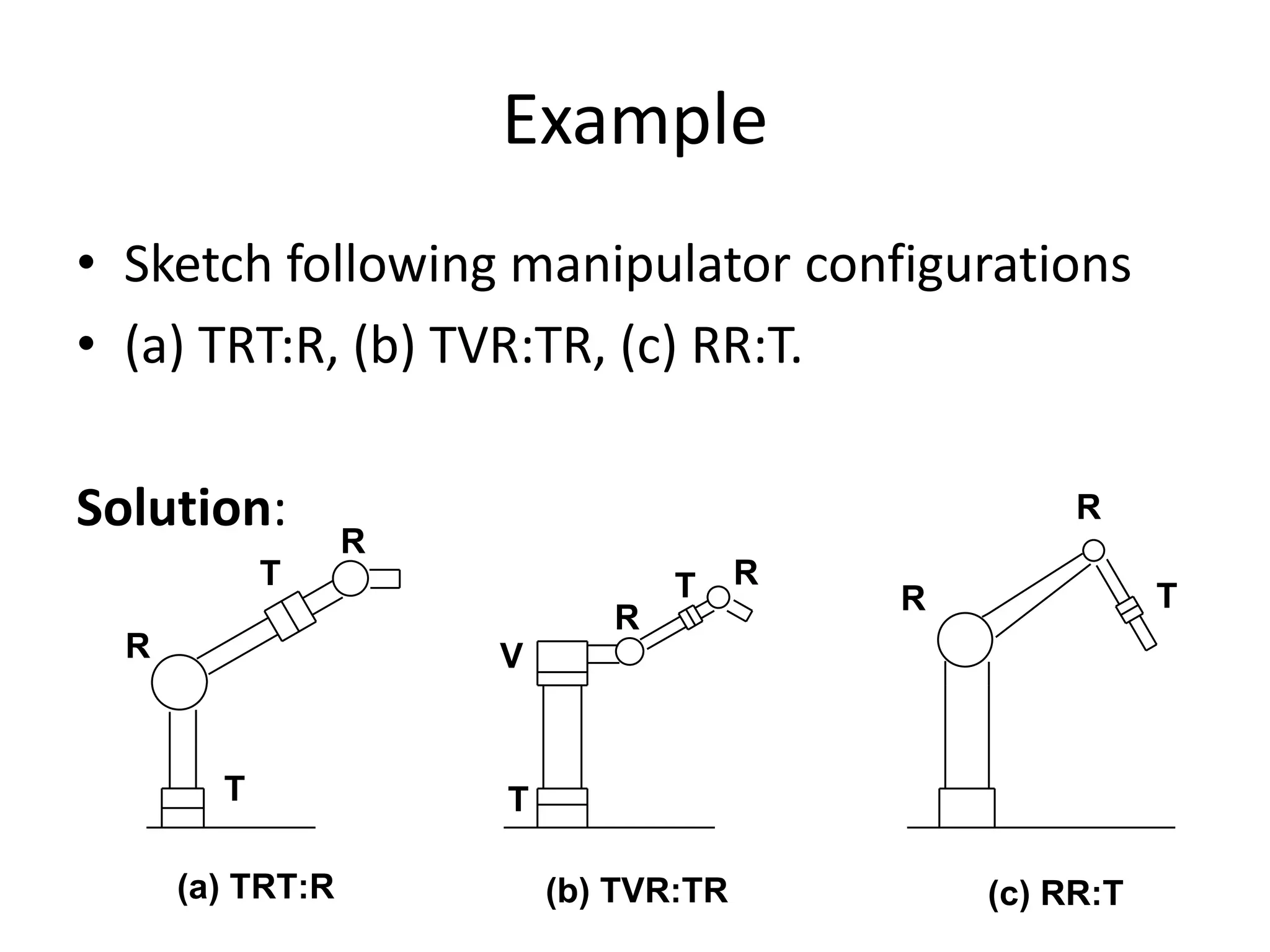
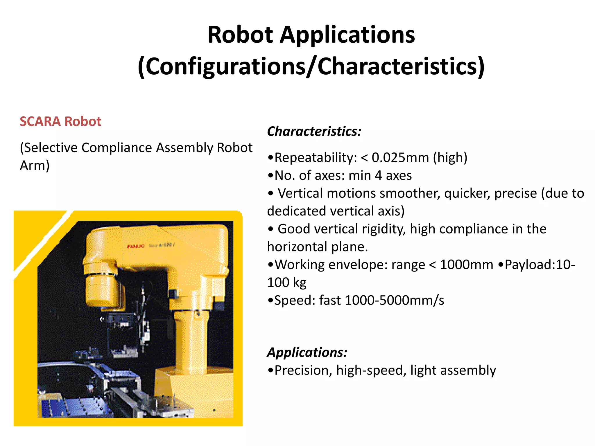
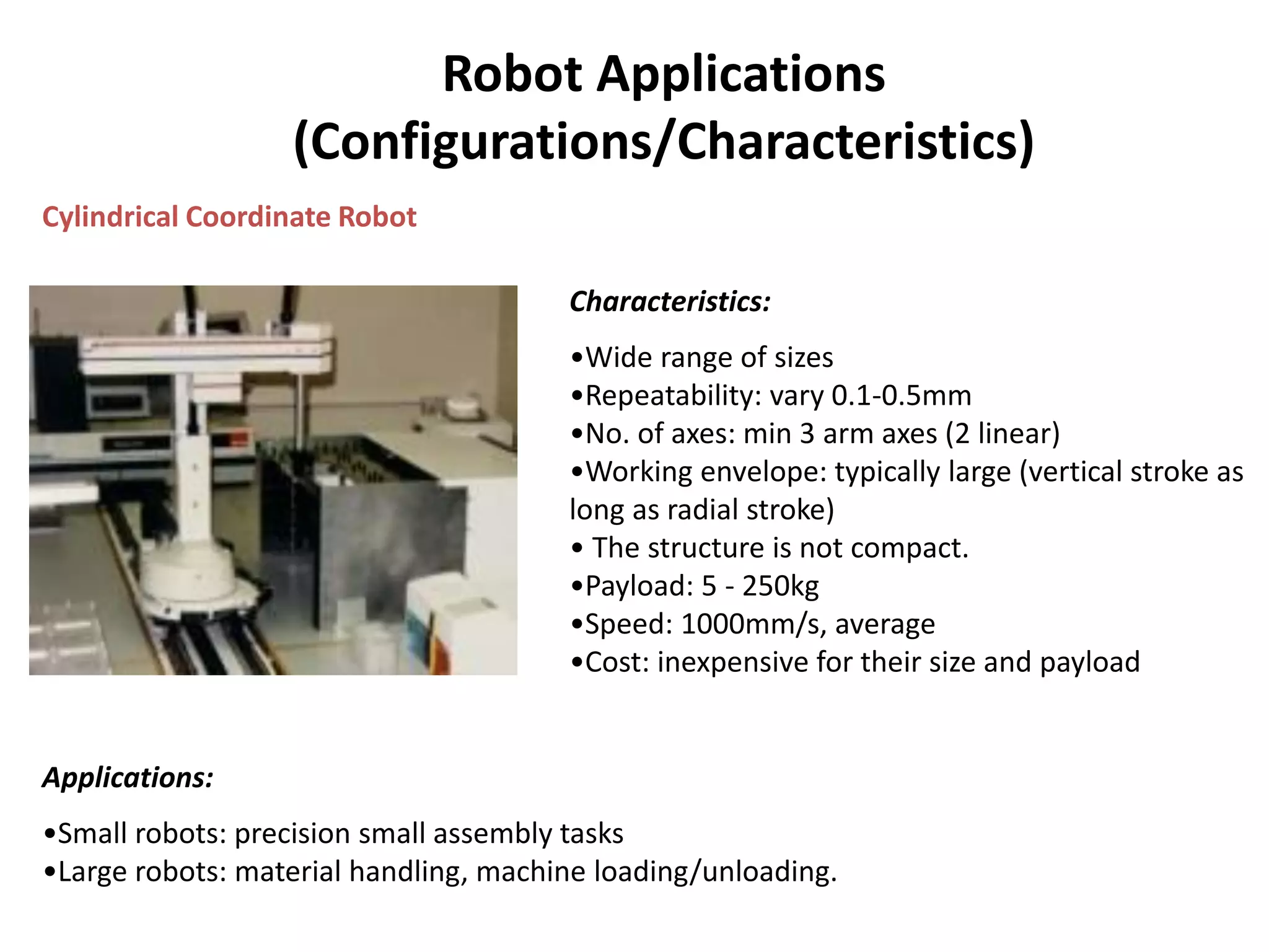
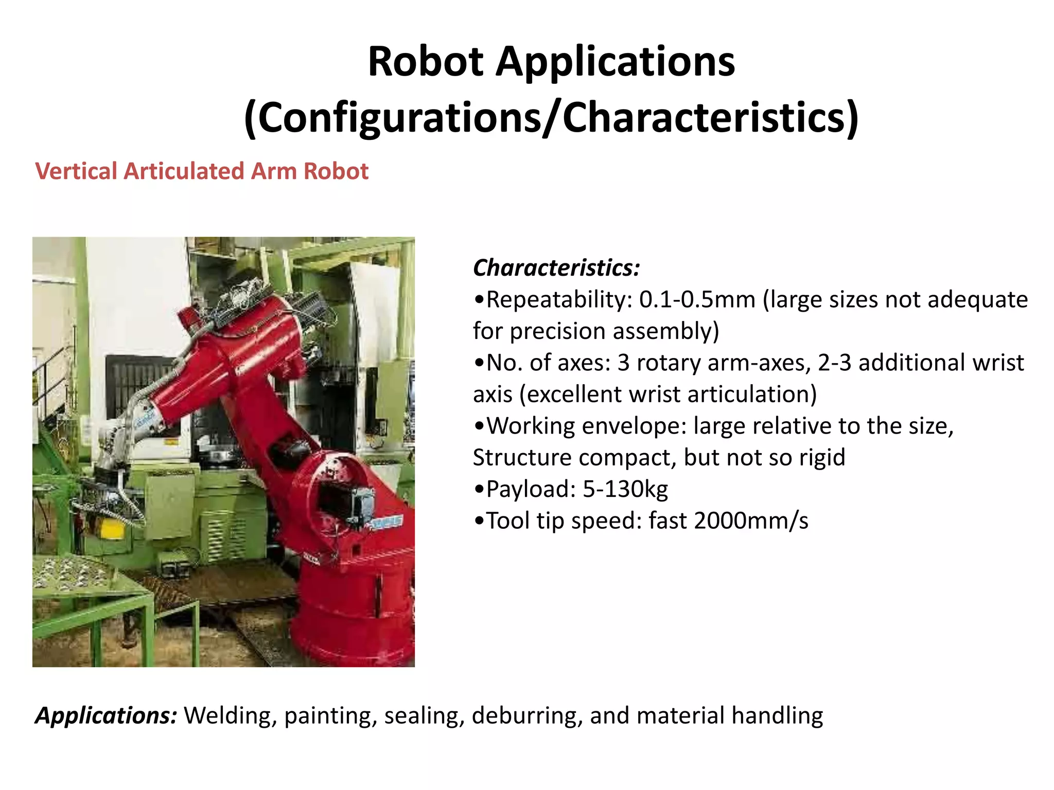
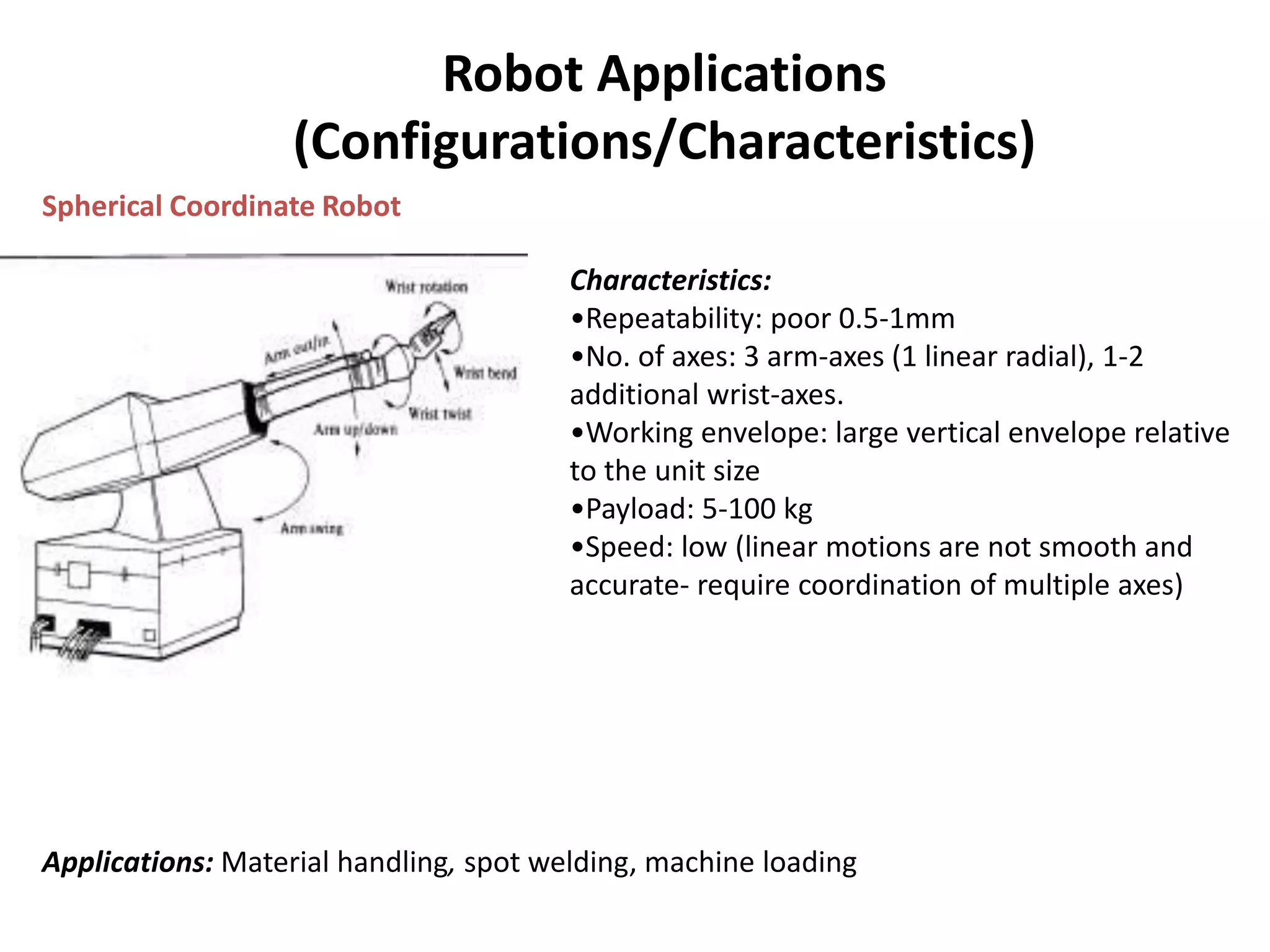
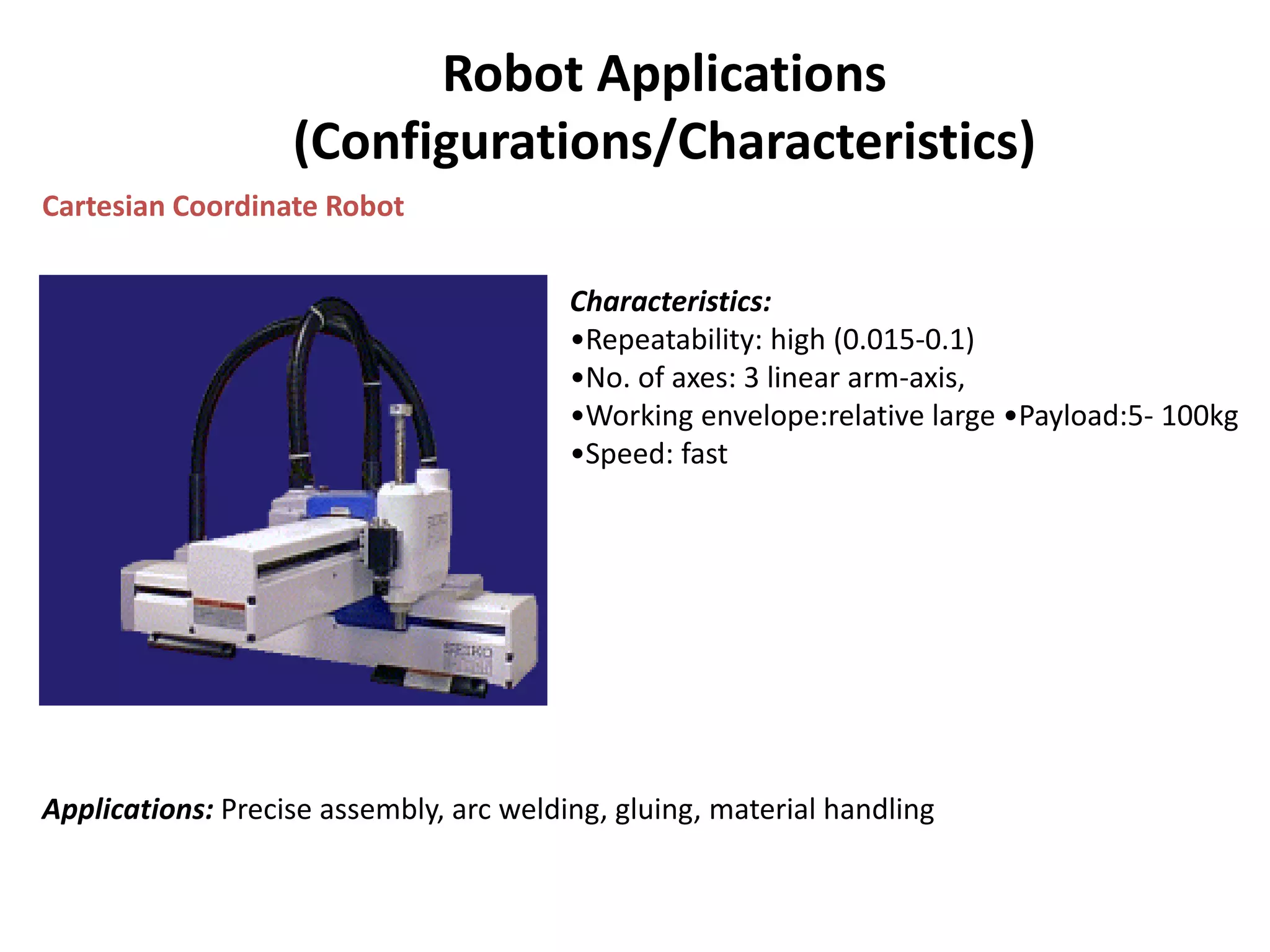
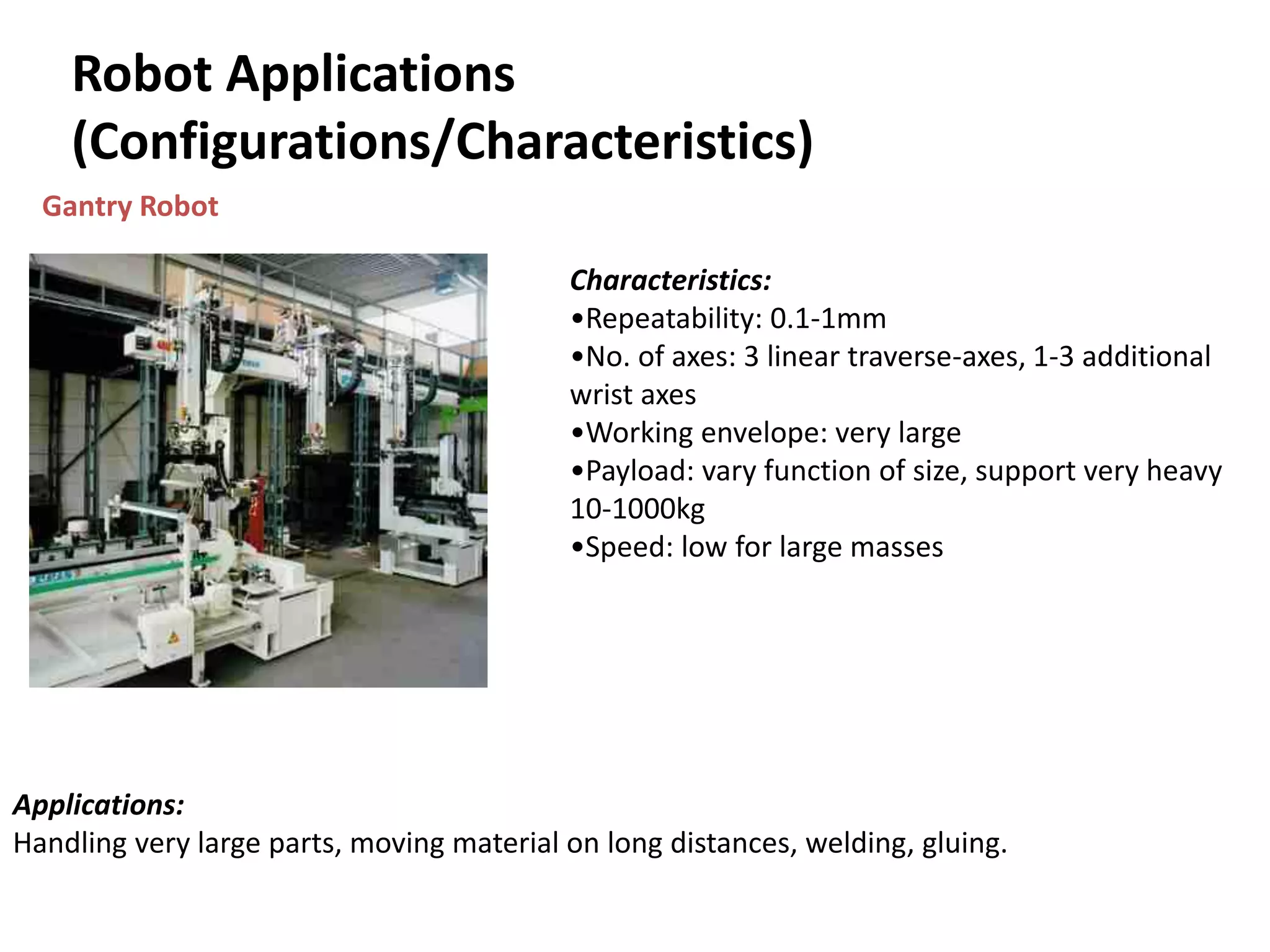
Overview of various types of robots, their configurations, characteristics, and tailored applications for industrial tasks.
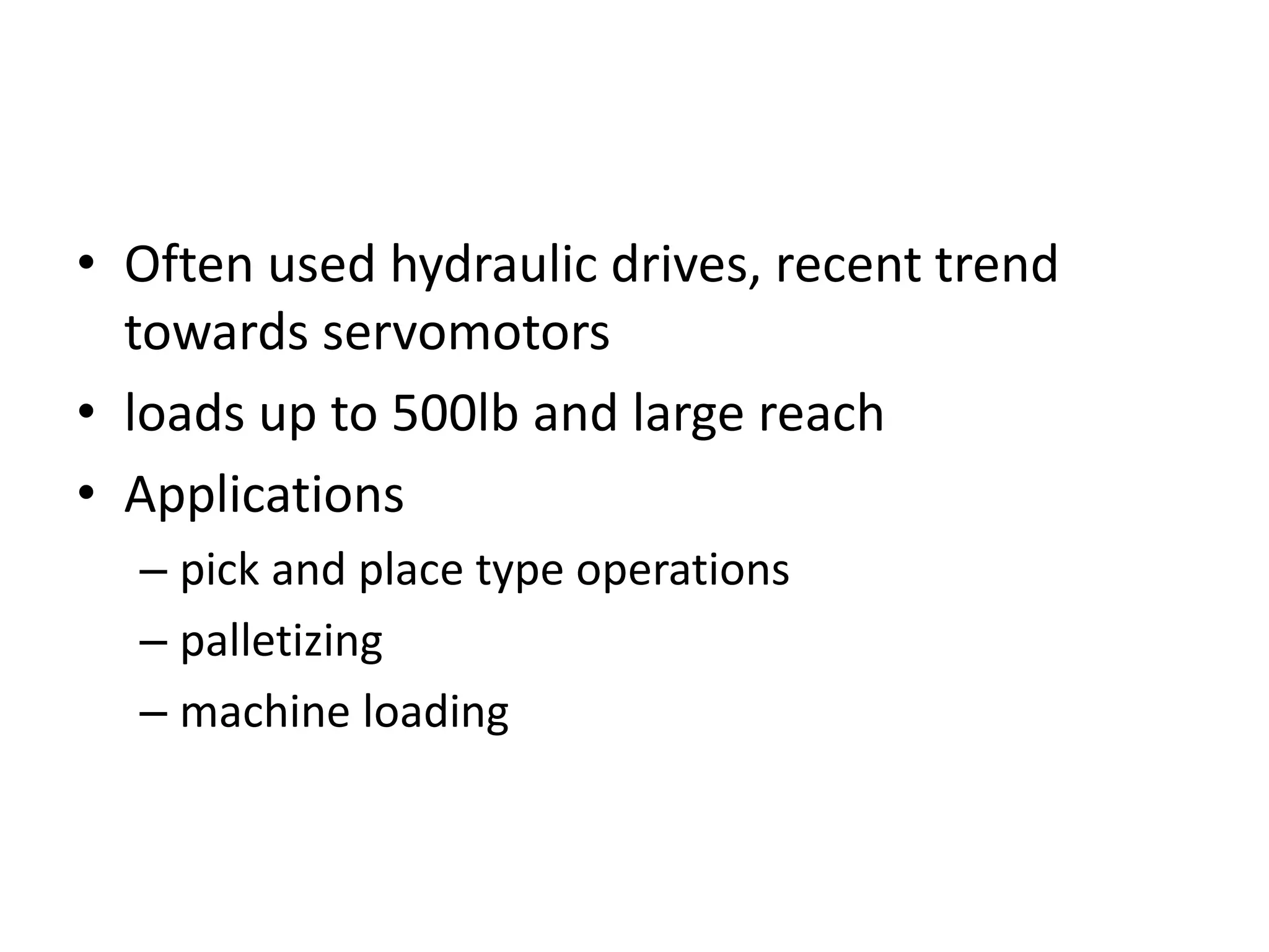
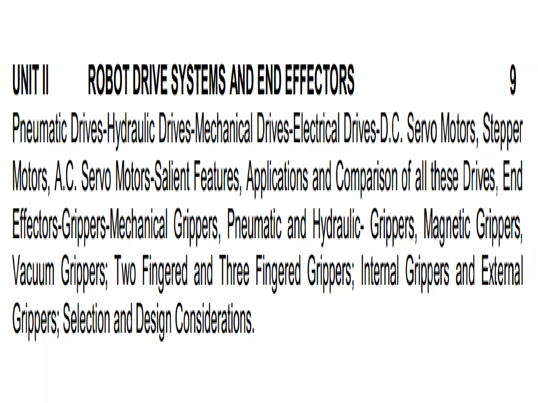
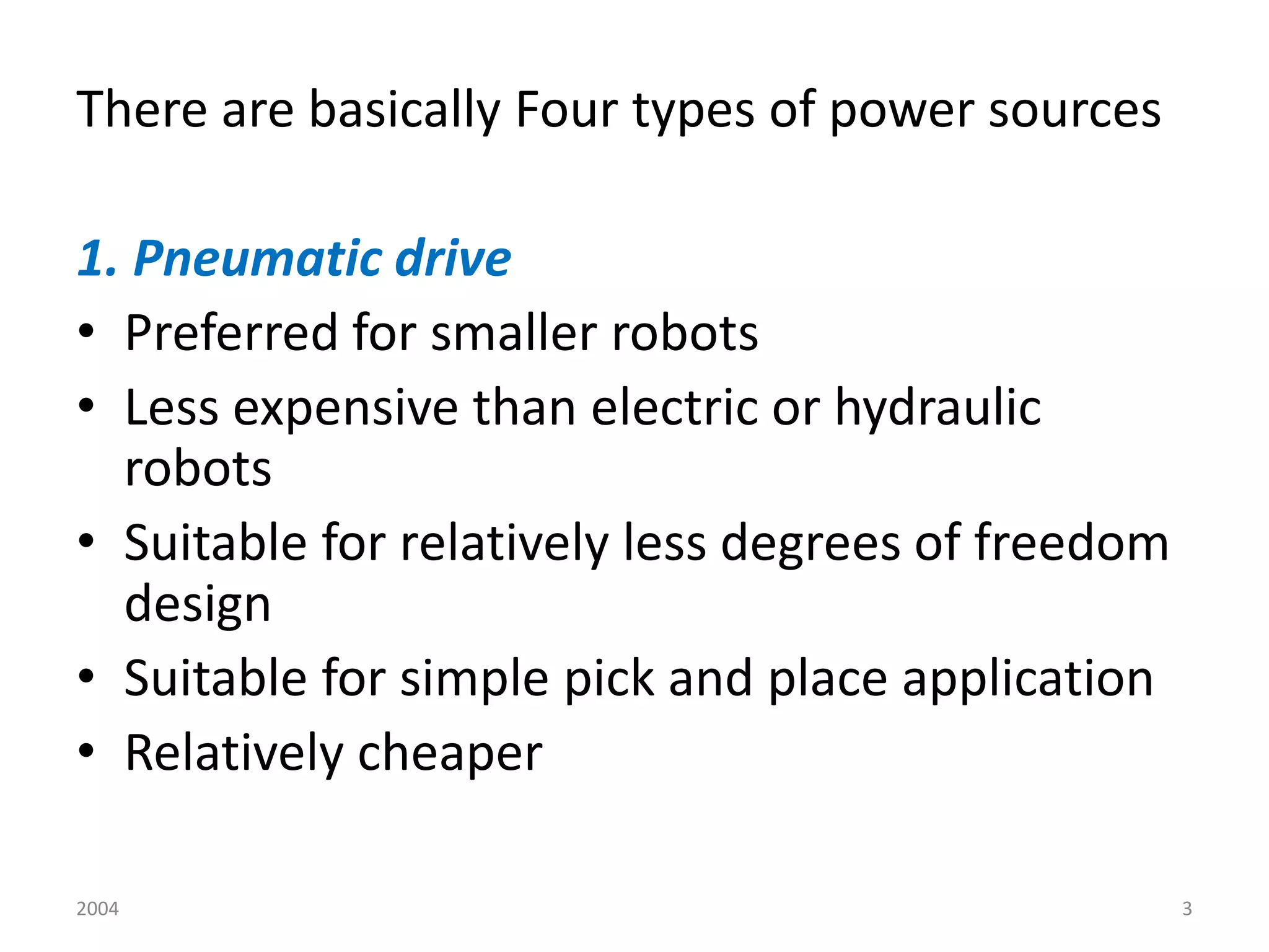
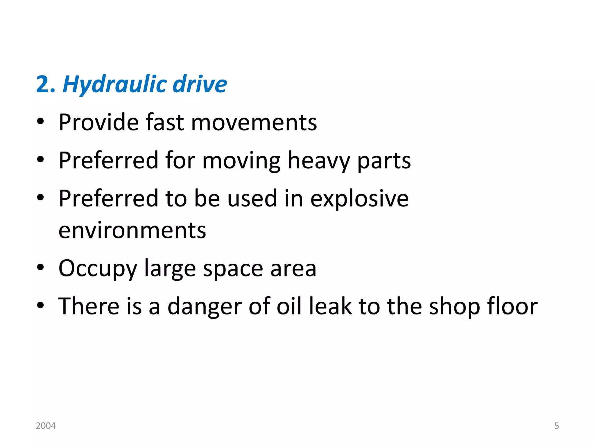
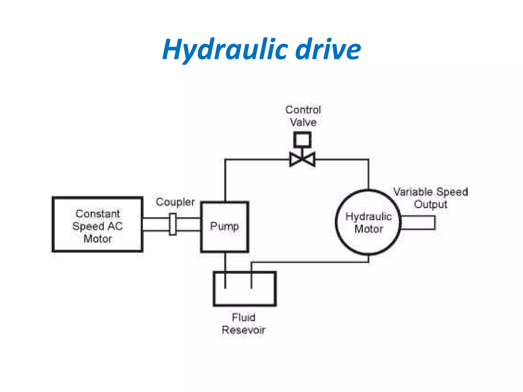
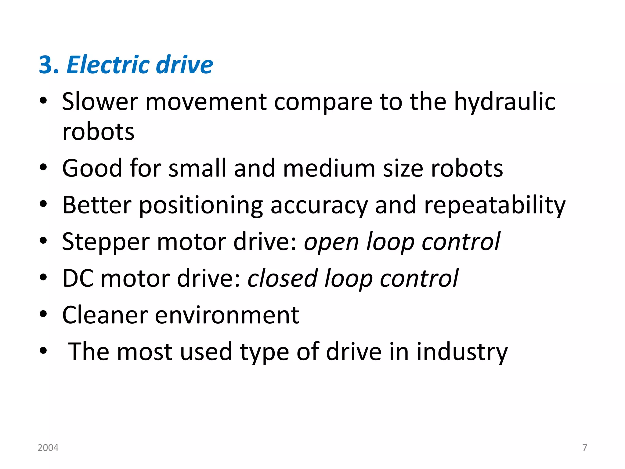
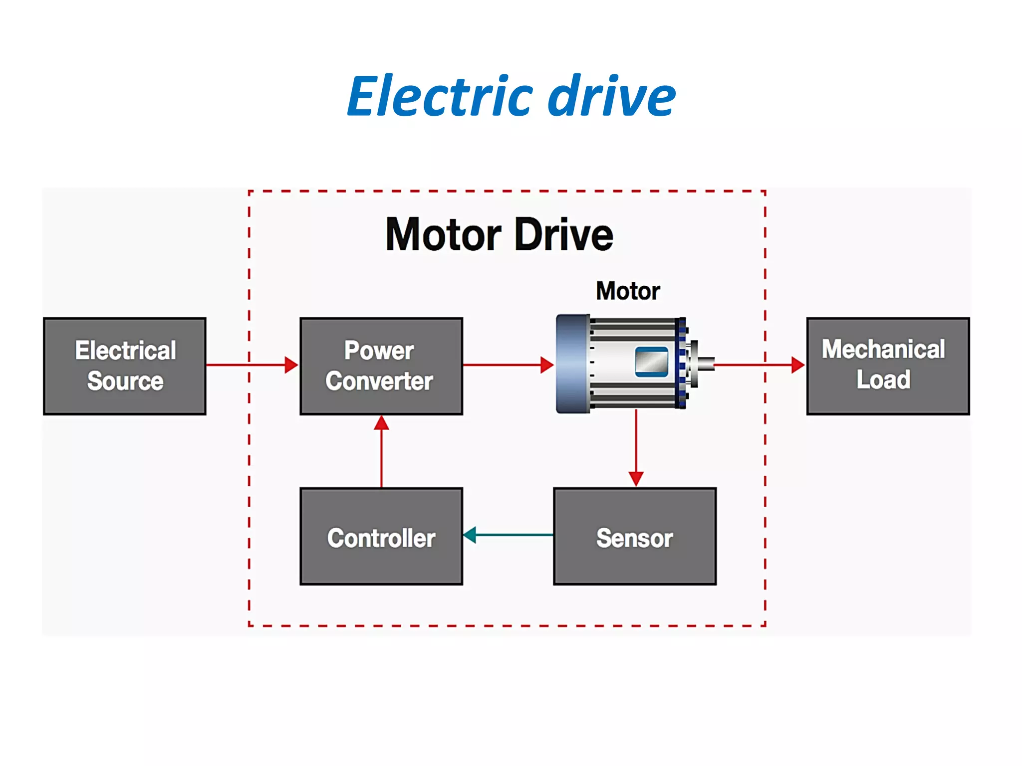
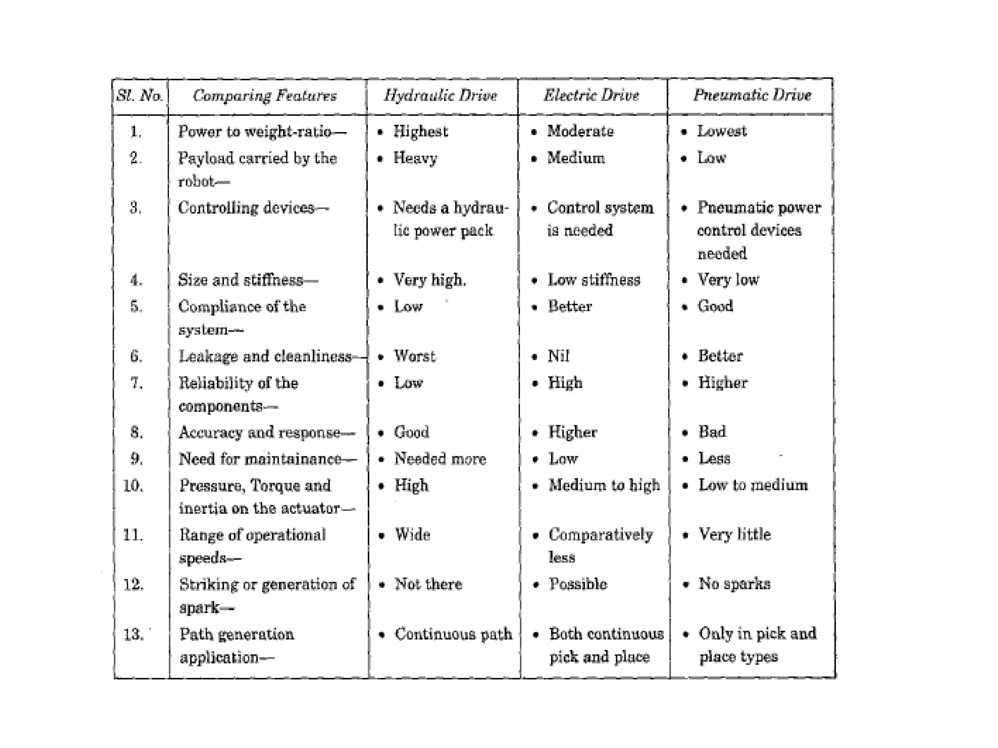
Detailed examination of drive systems for robots including types such as pneumatic, hydraulic, and electric drives.
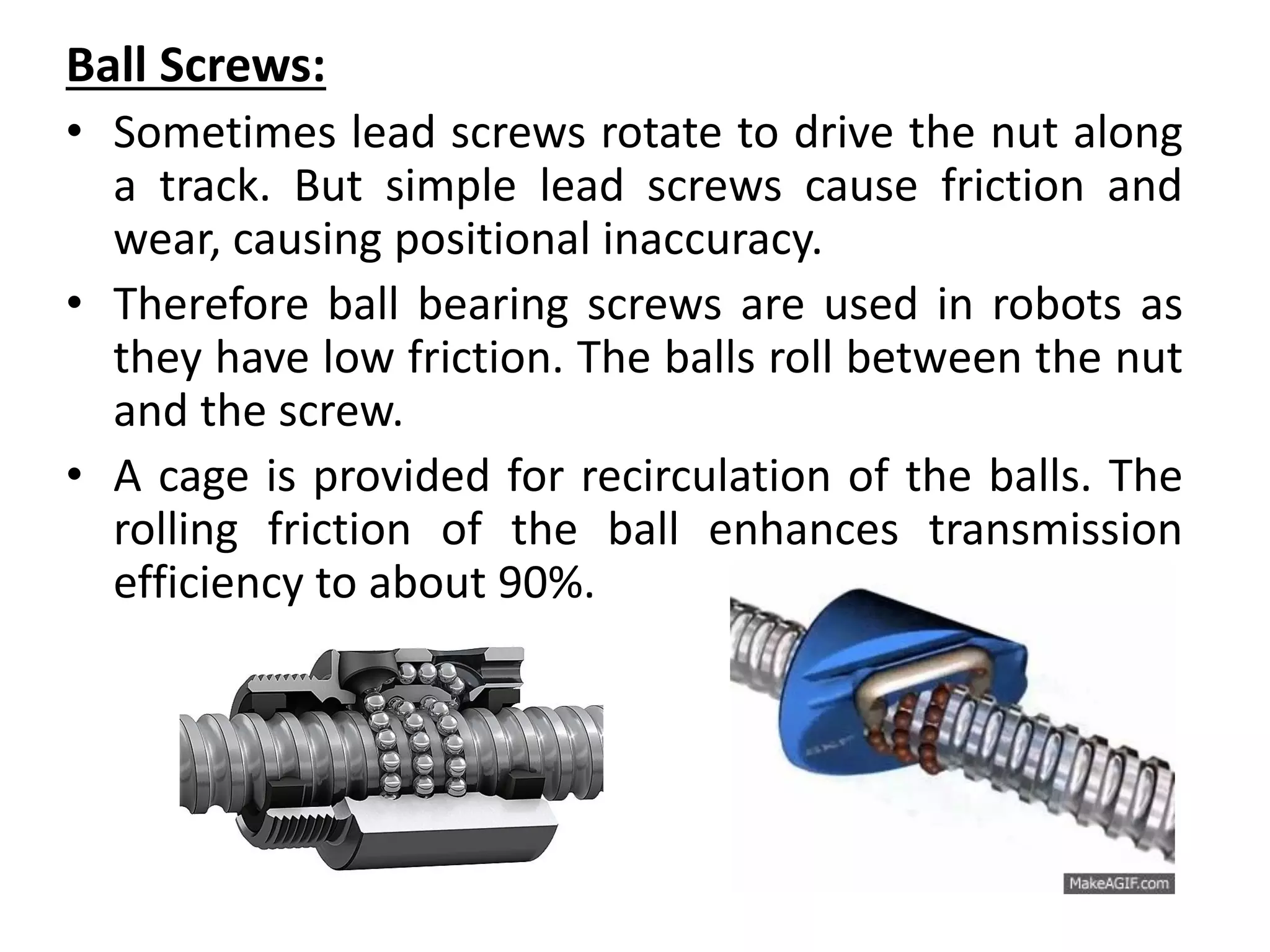
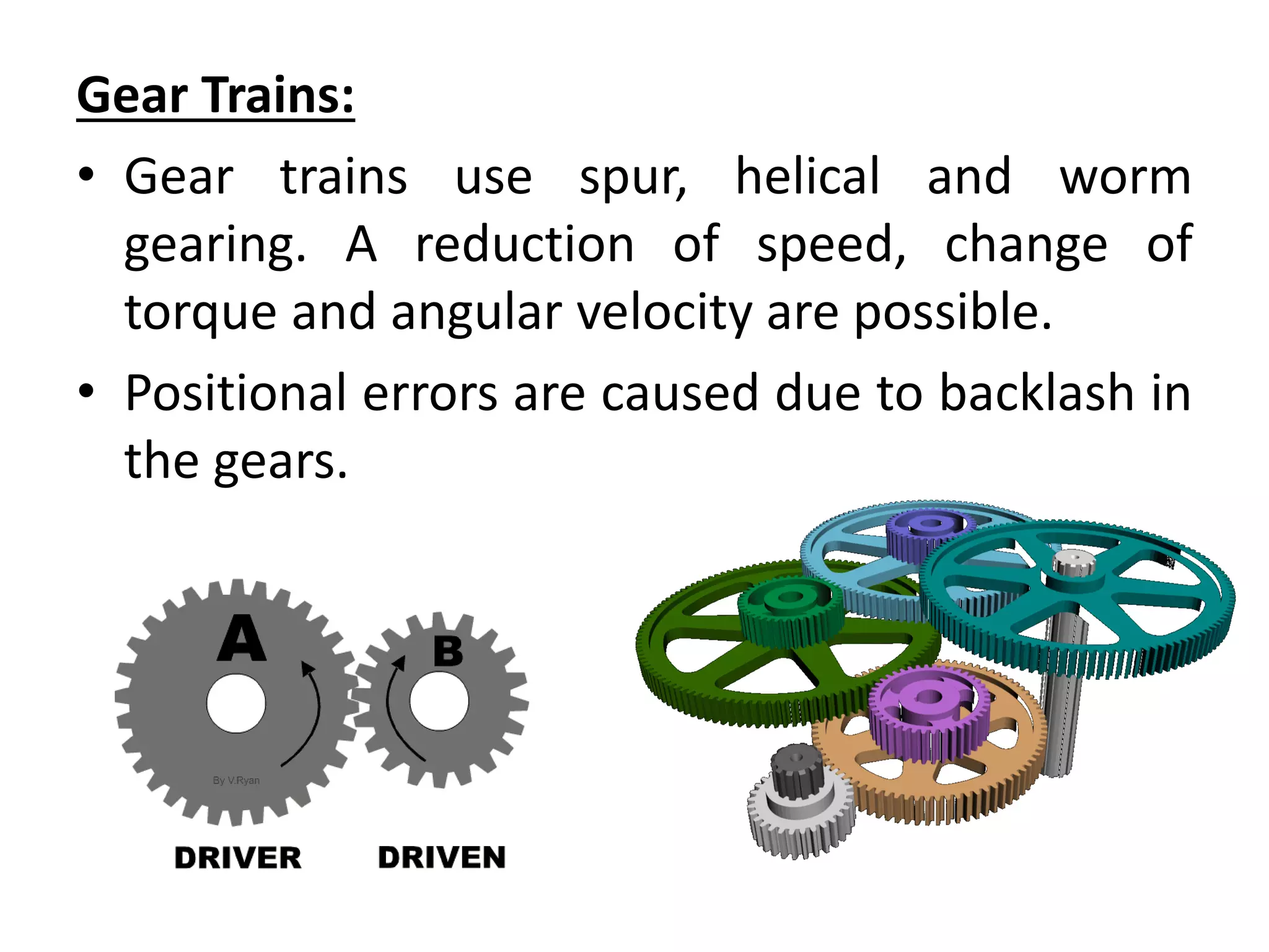
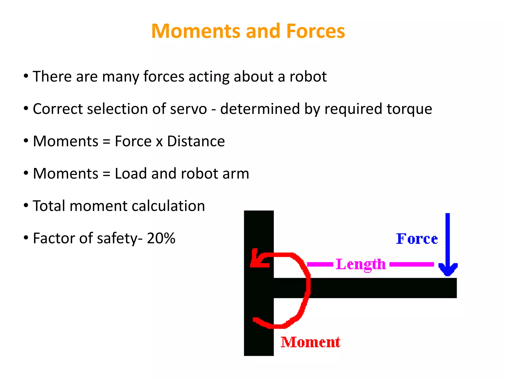
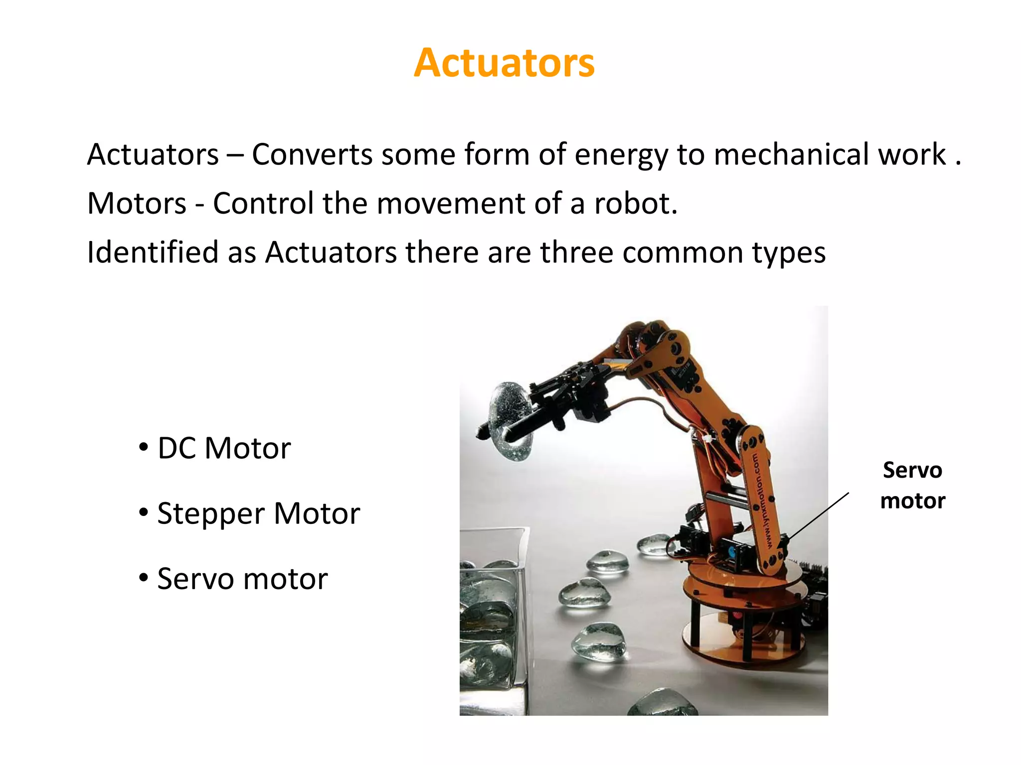
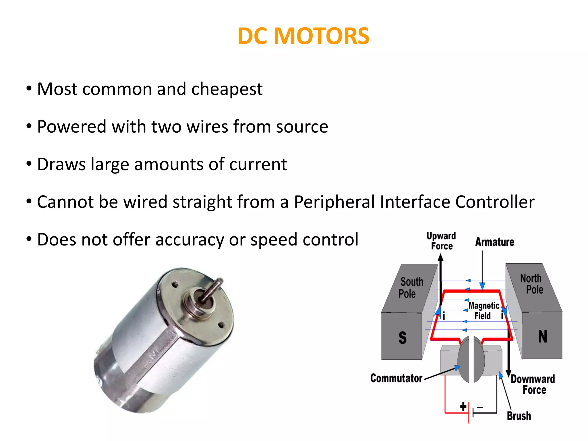
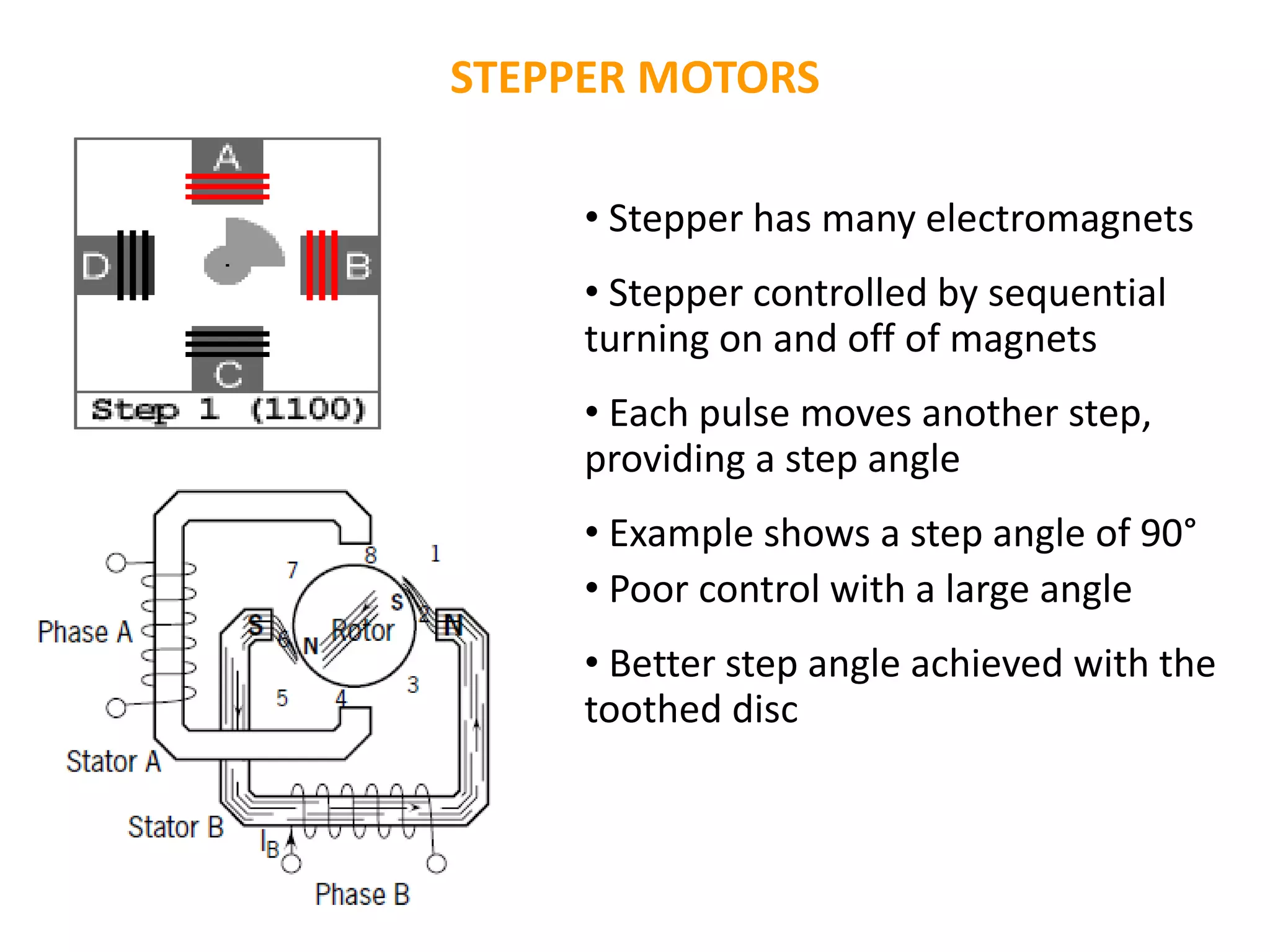
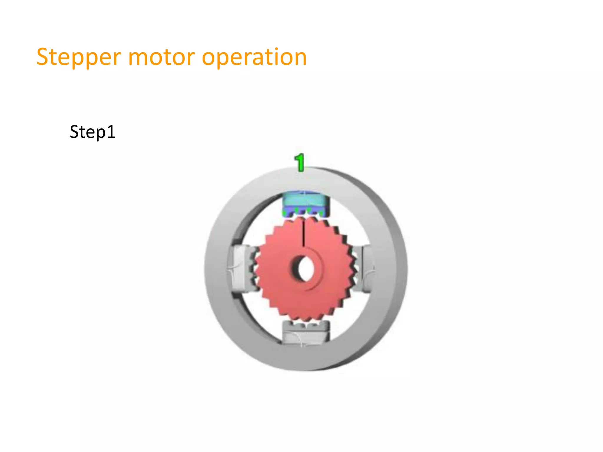
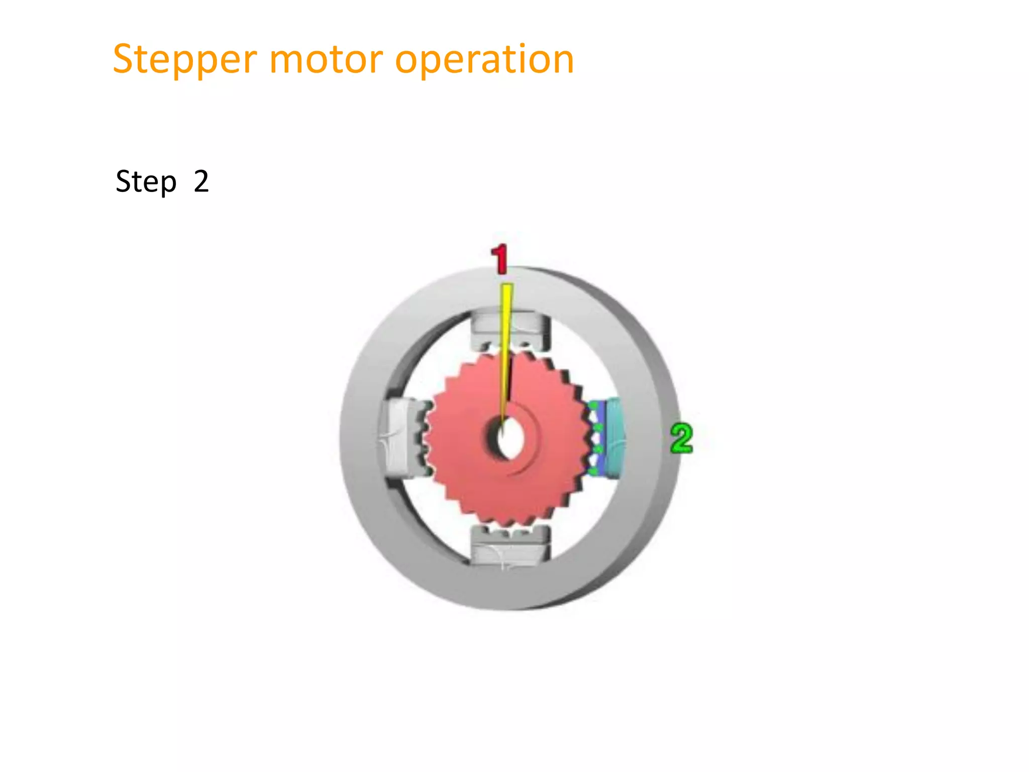
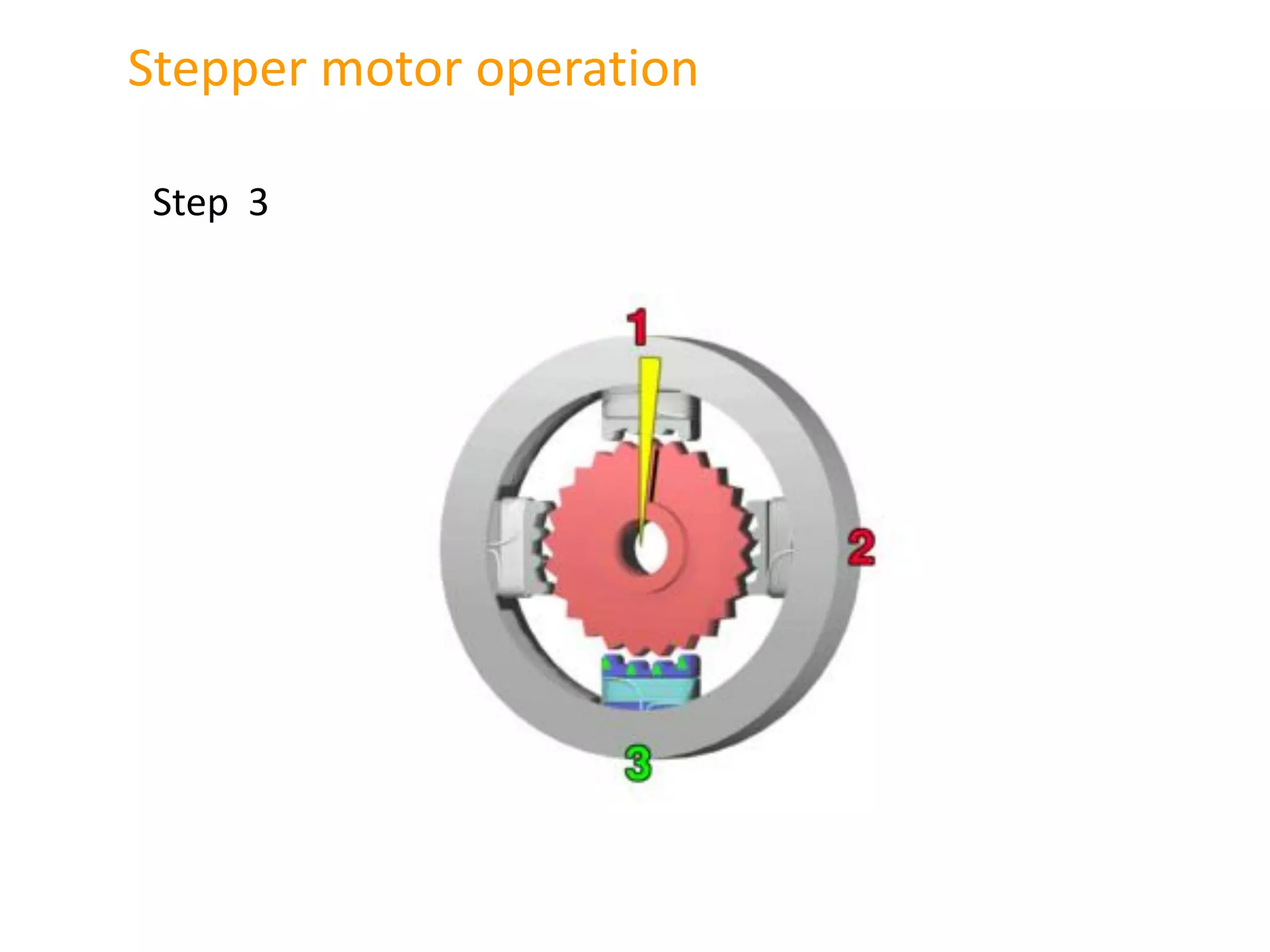
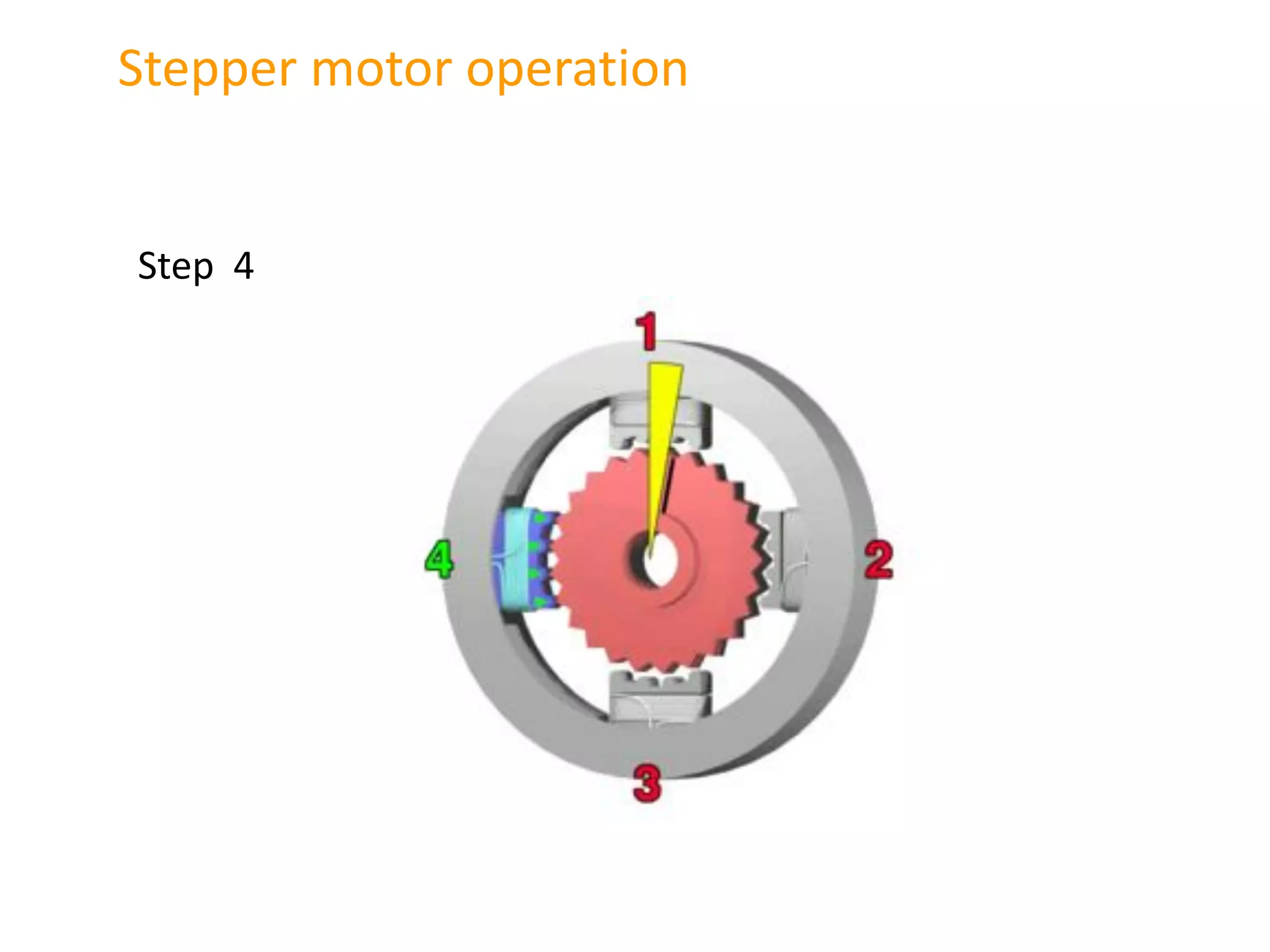
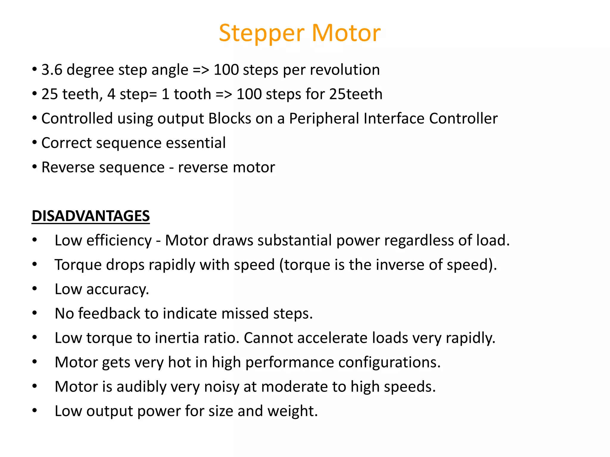
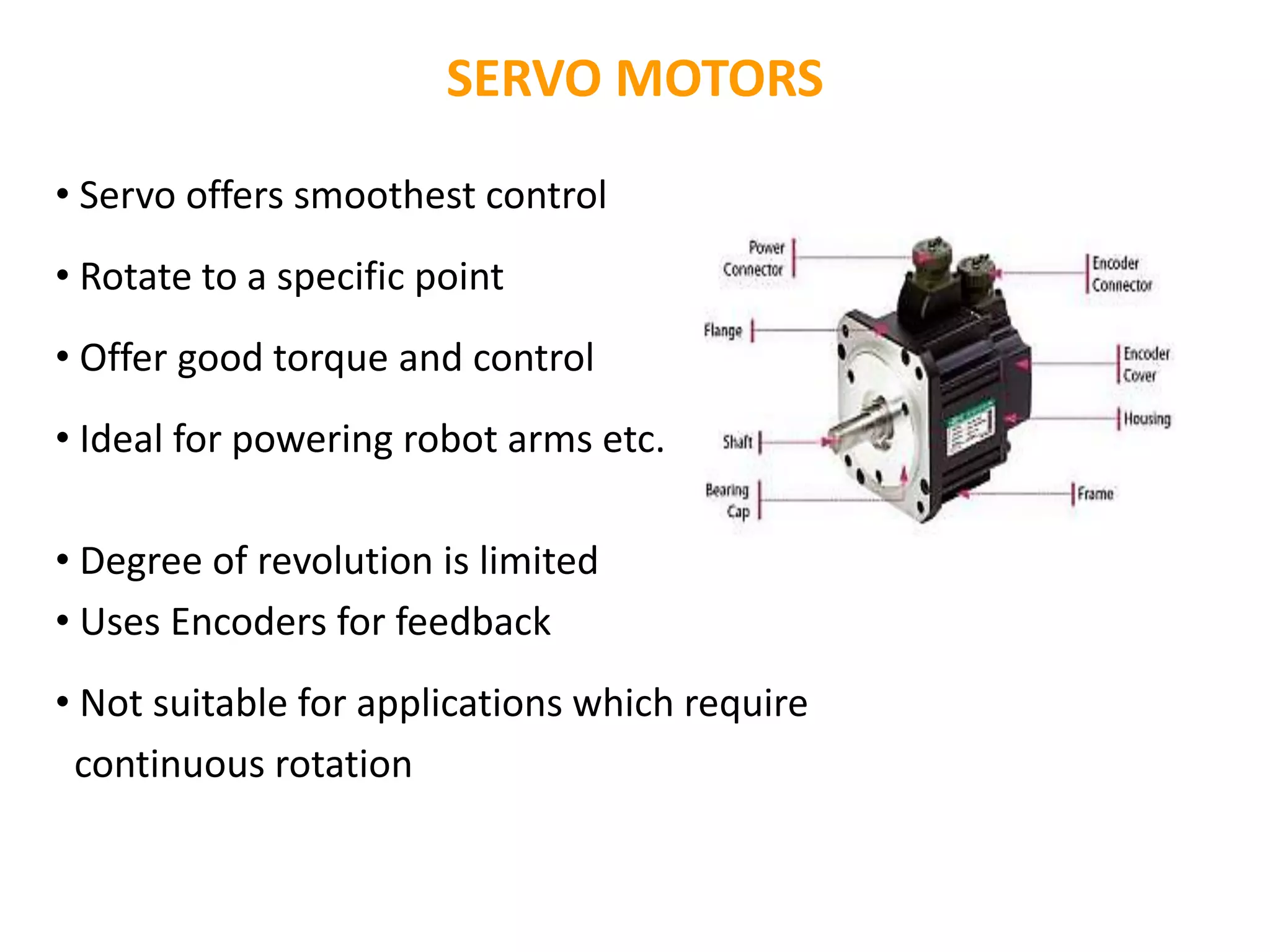
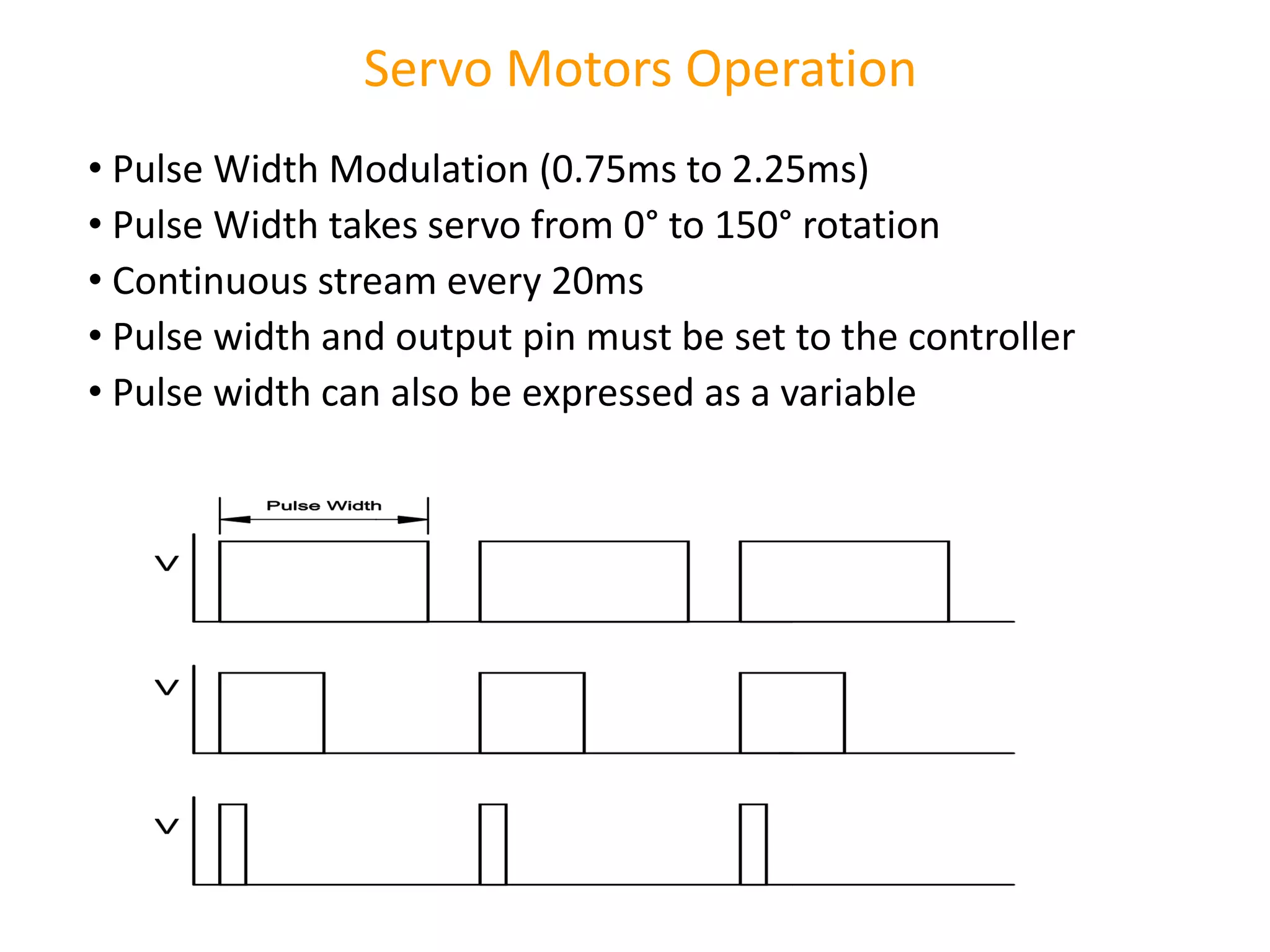
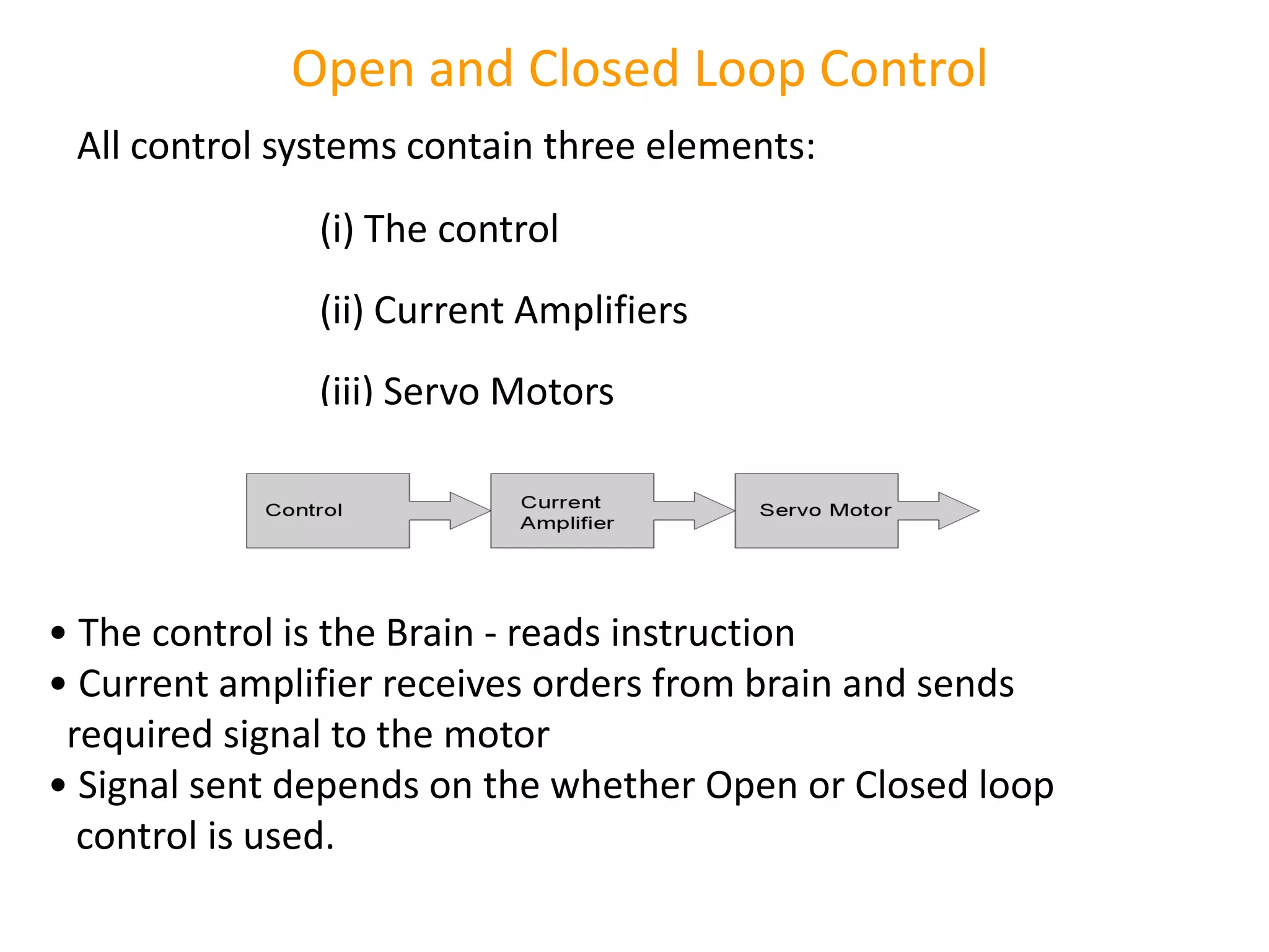
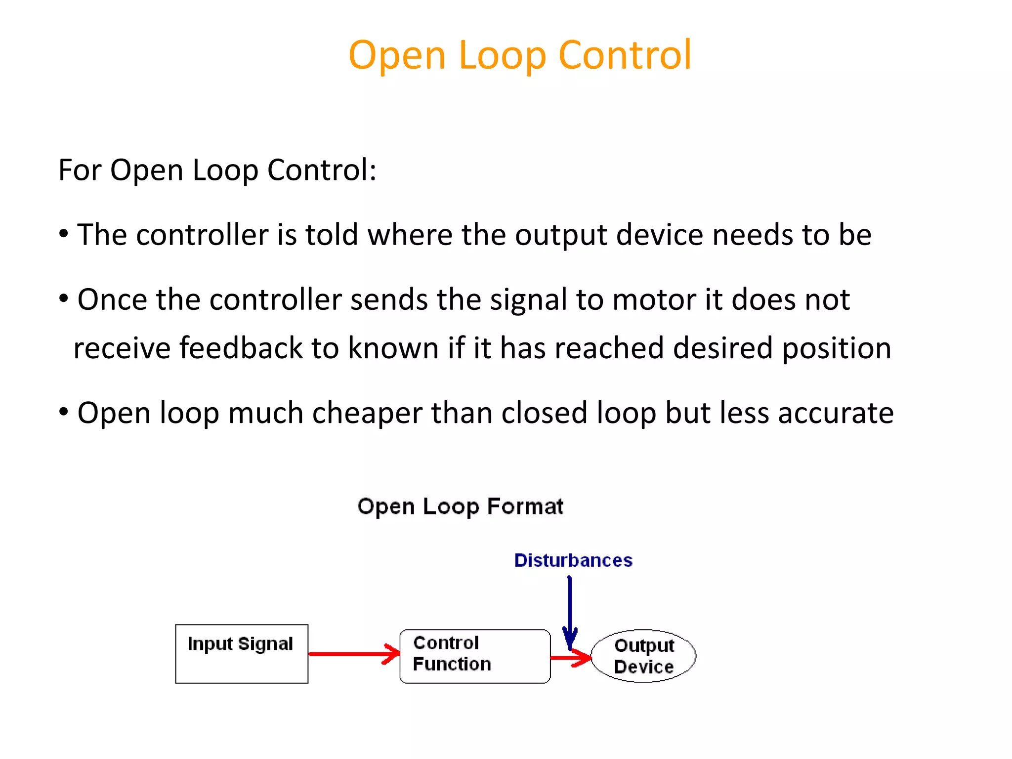
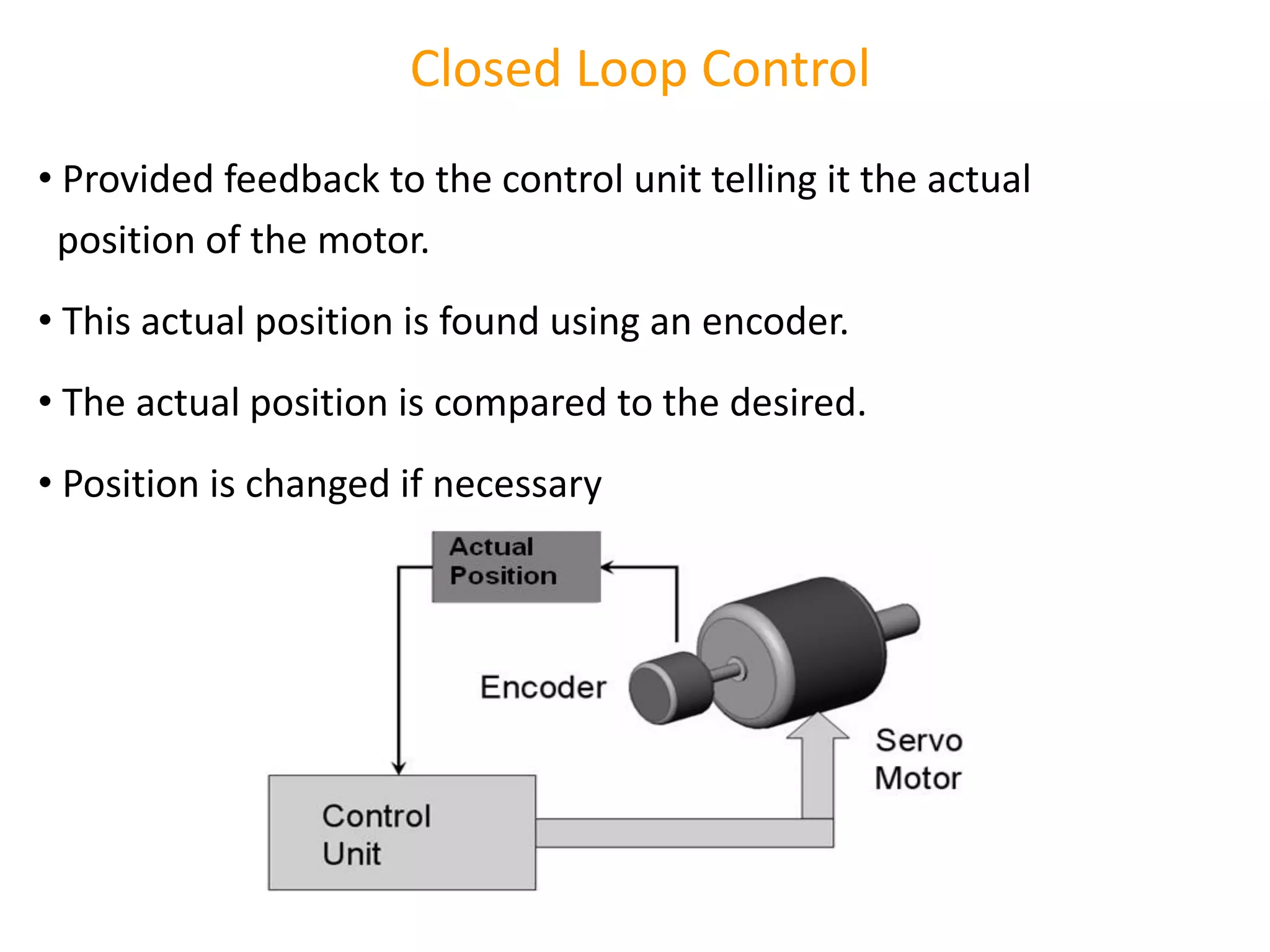
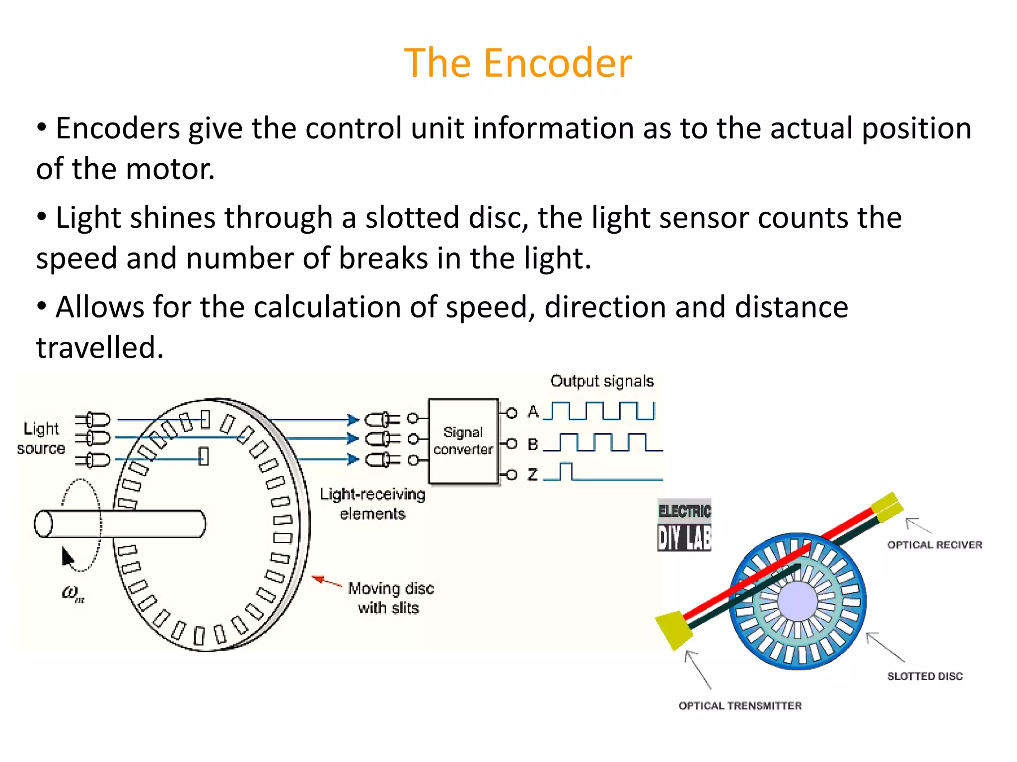
Actuators types like DC, stepper, and servo; control systems and their significance in robot movement and positioning.
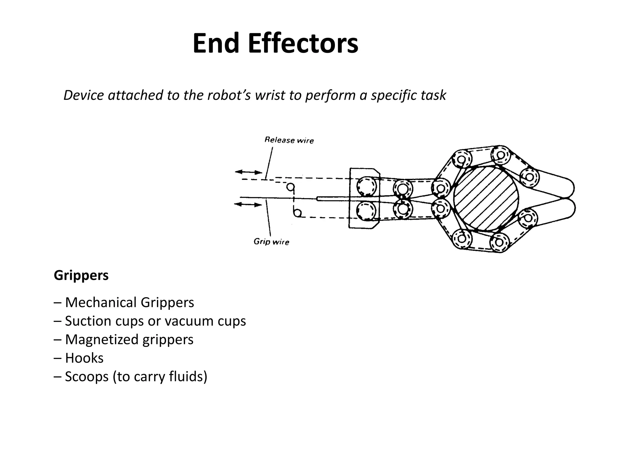
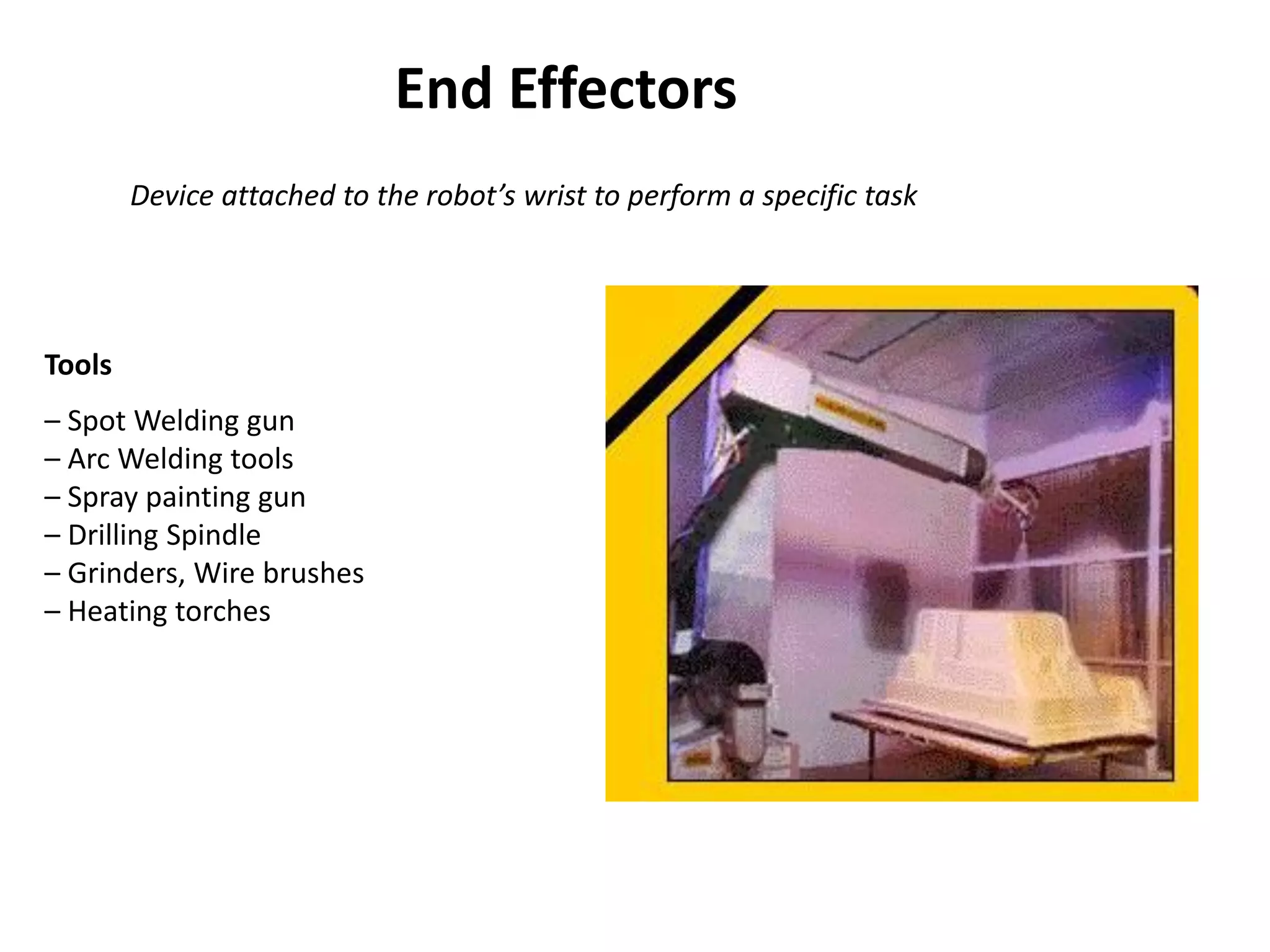
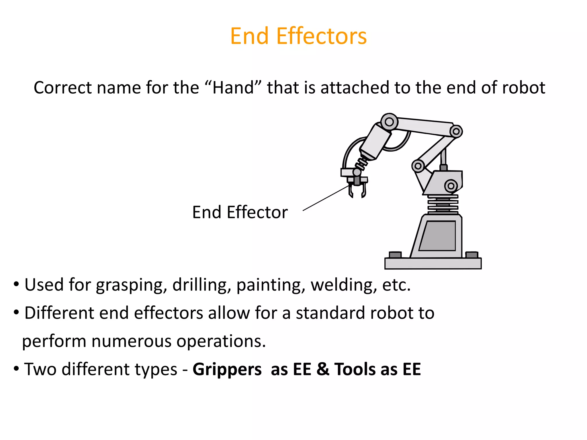
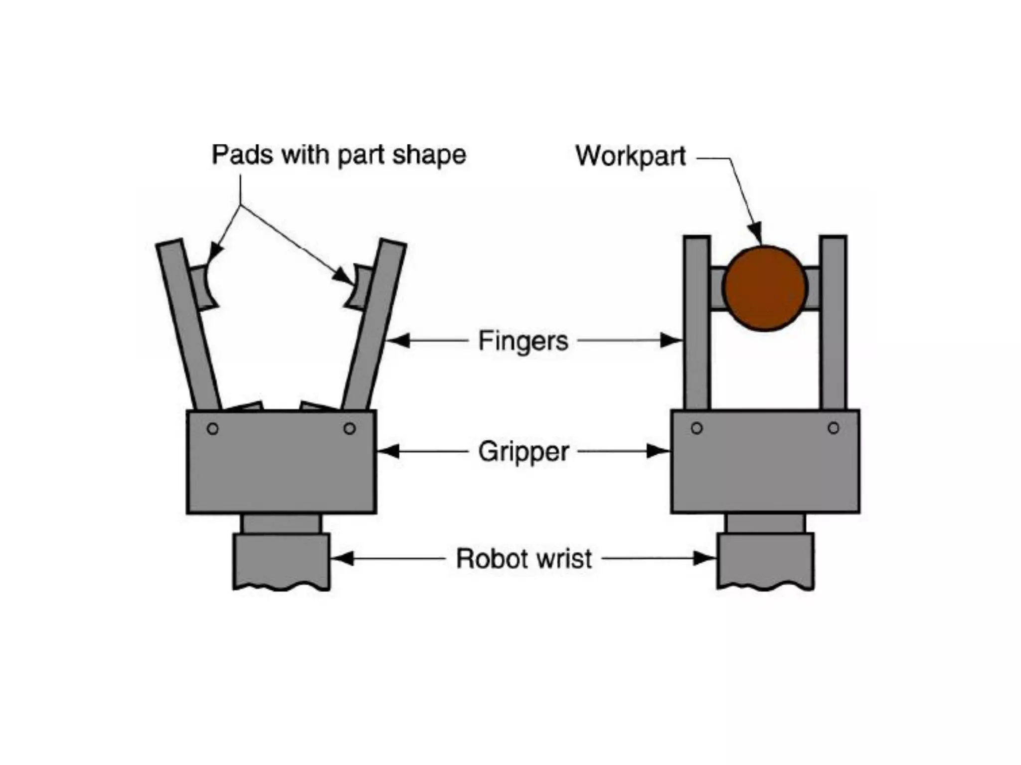
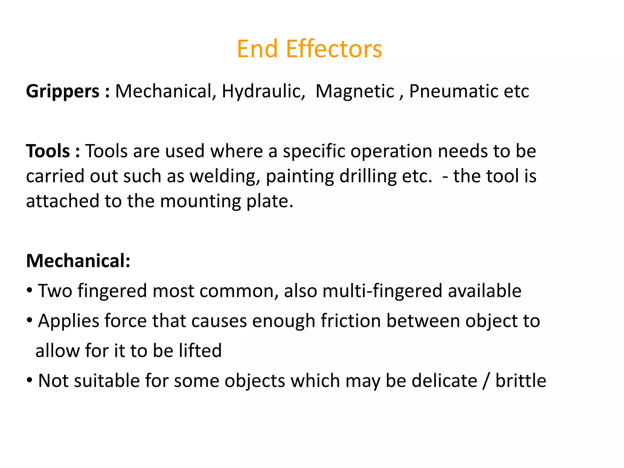
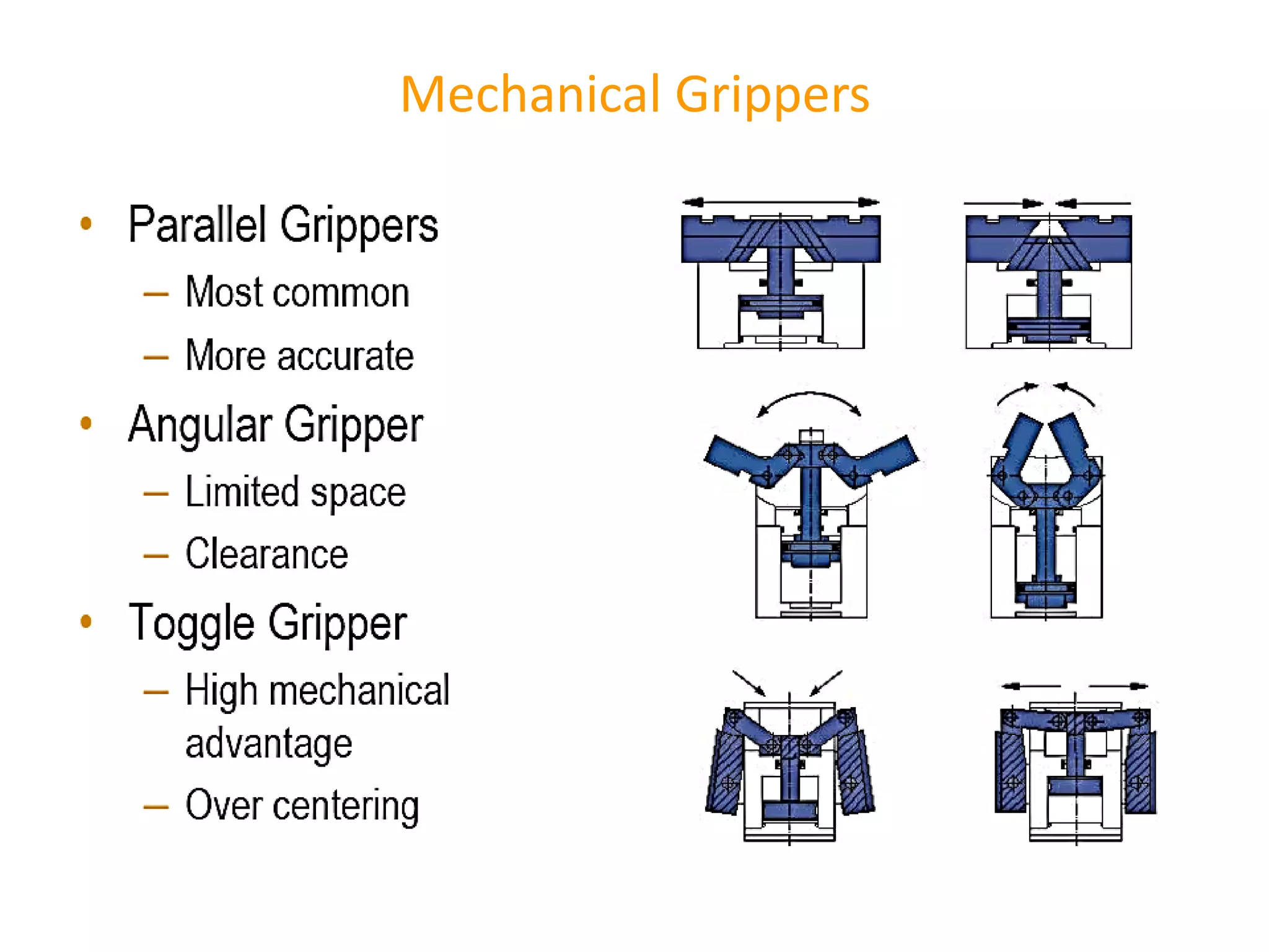
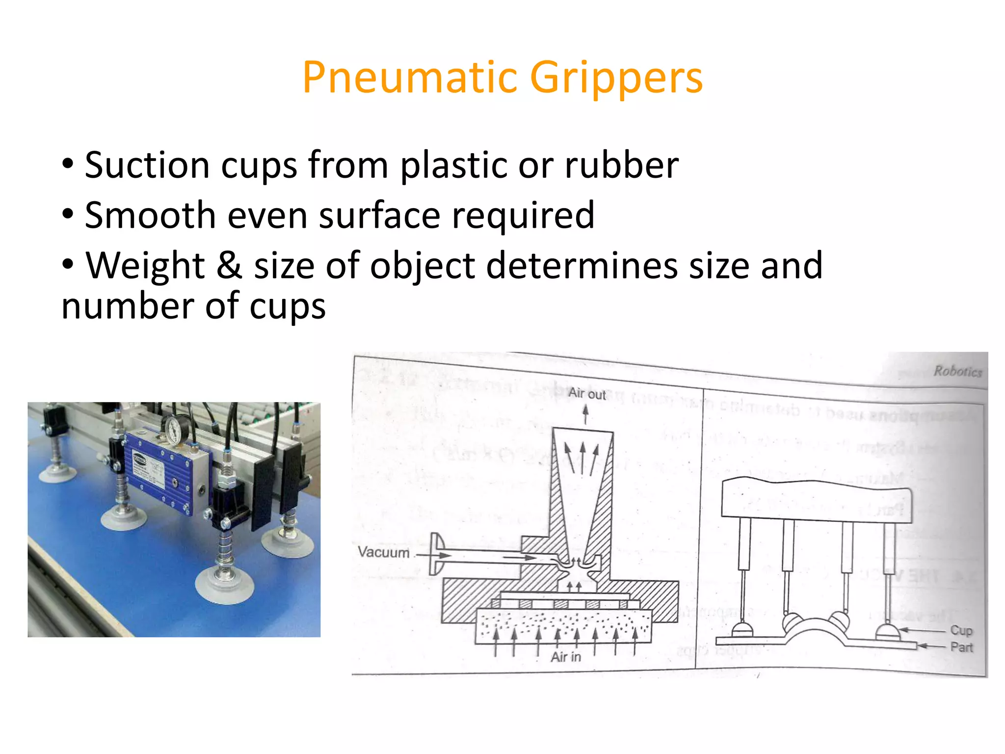
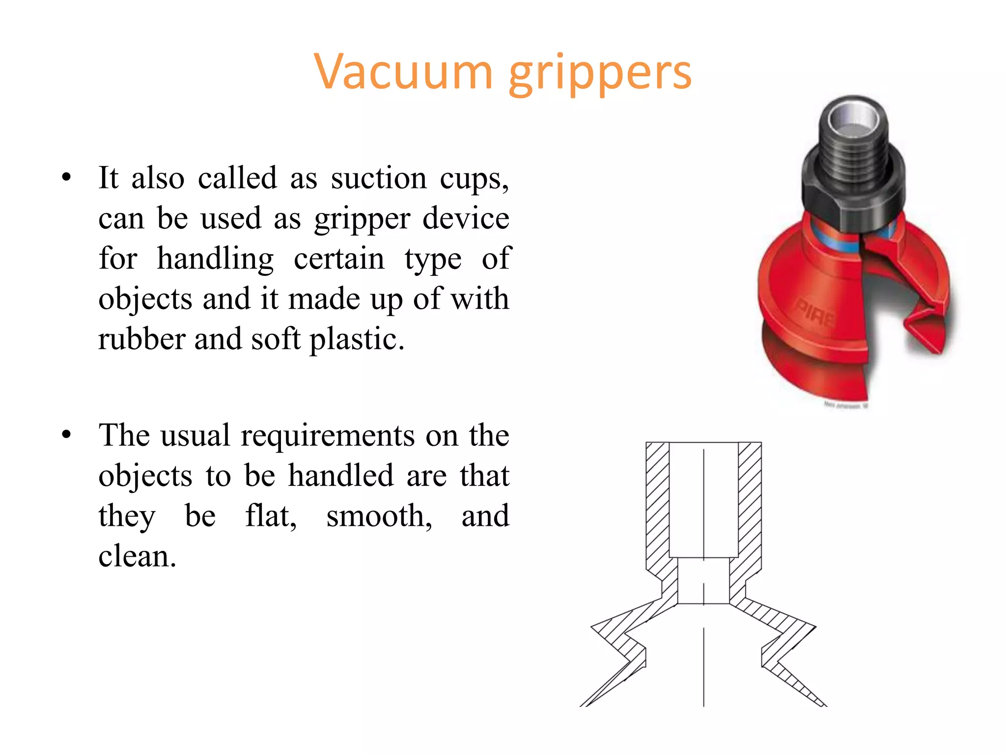
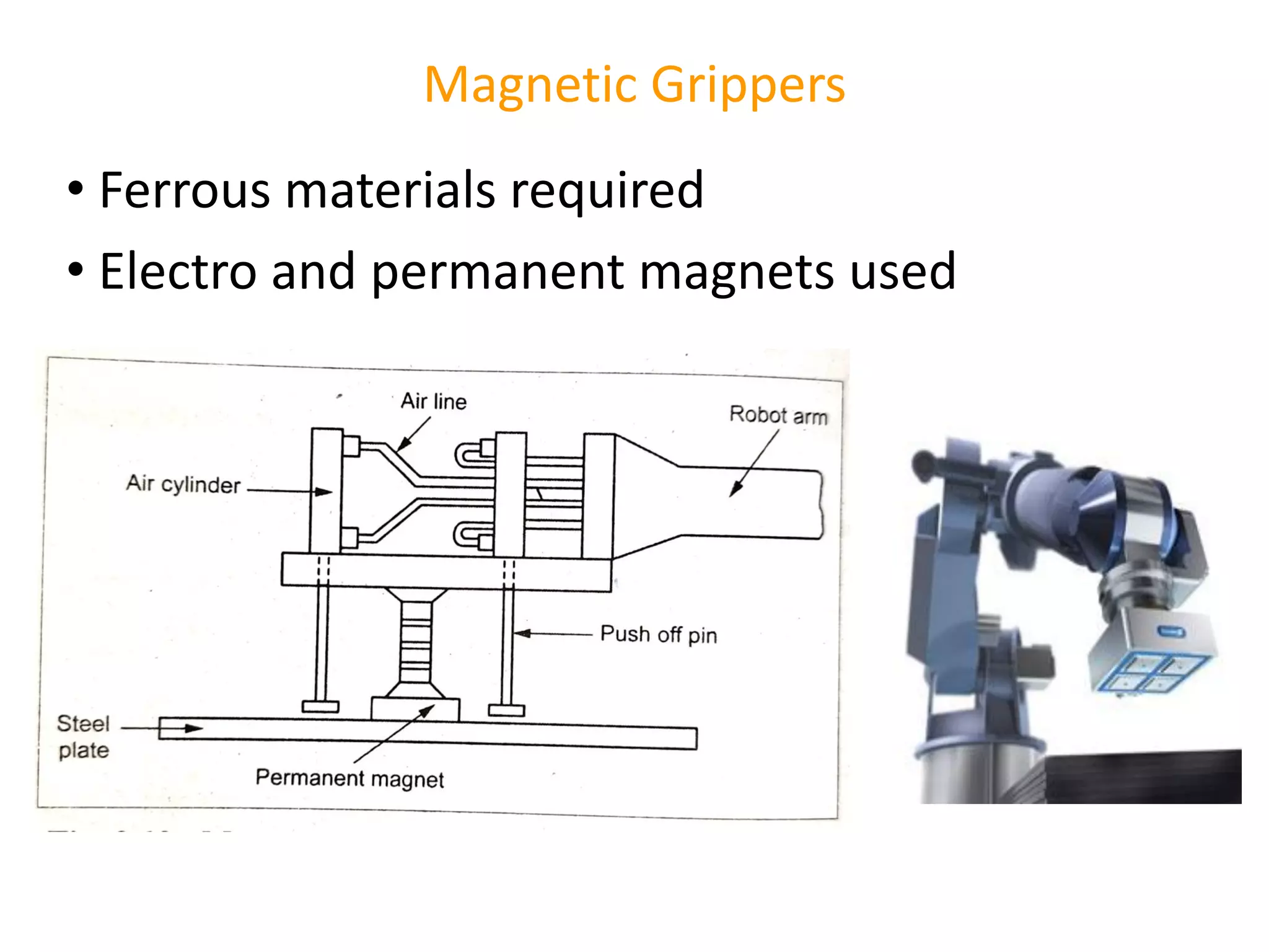
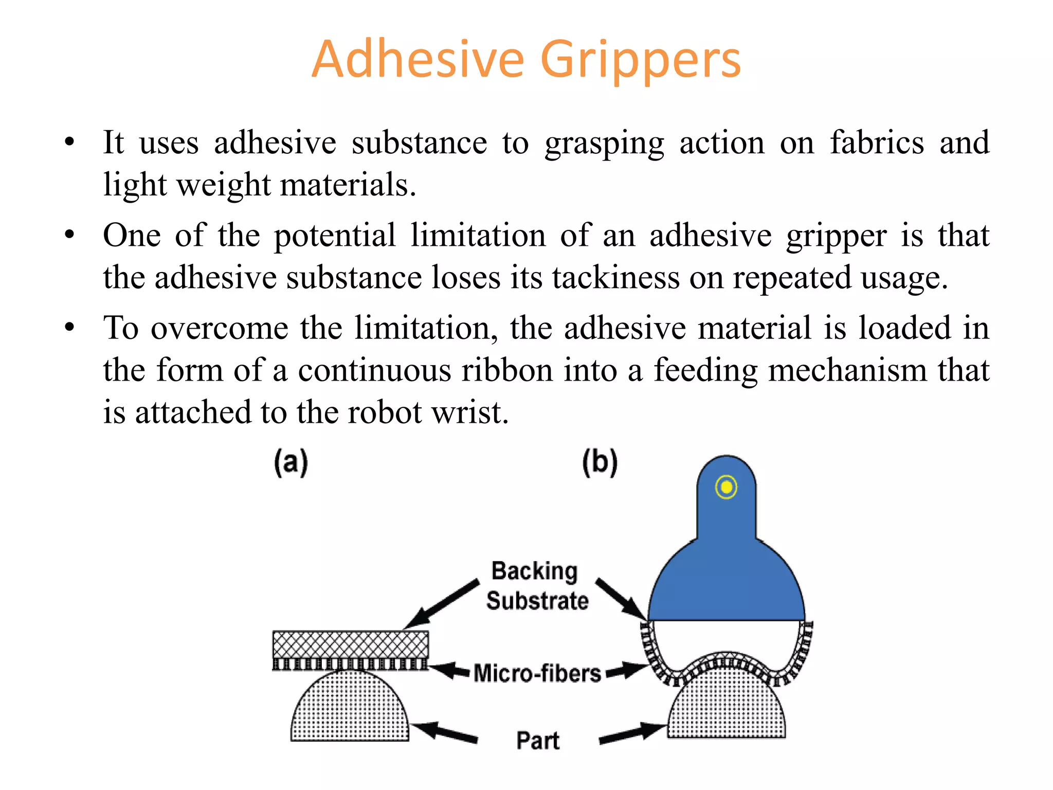
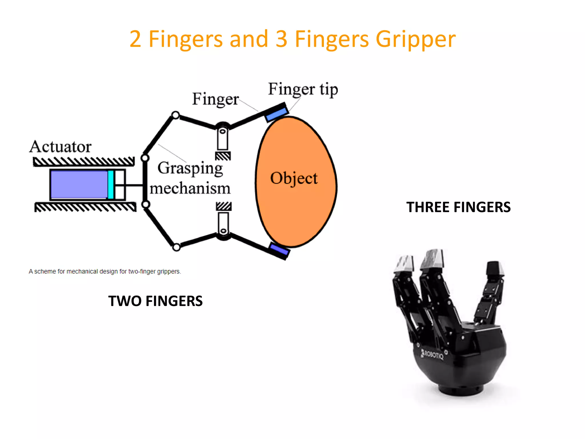
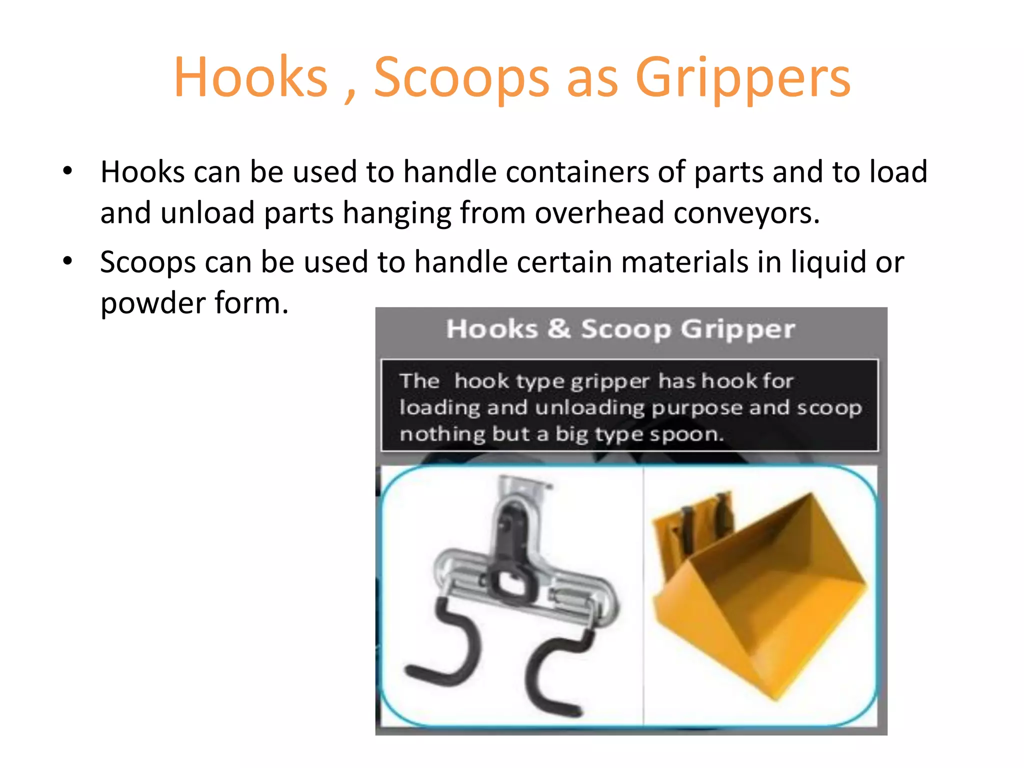
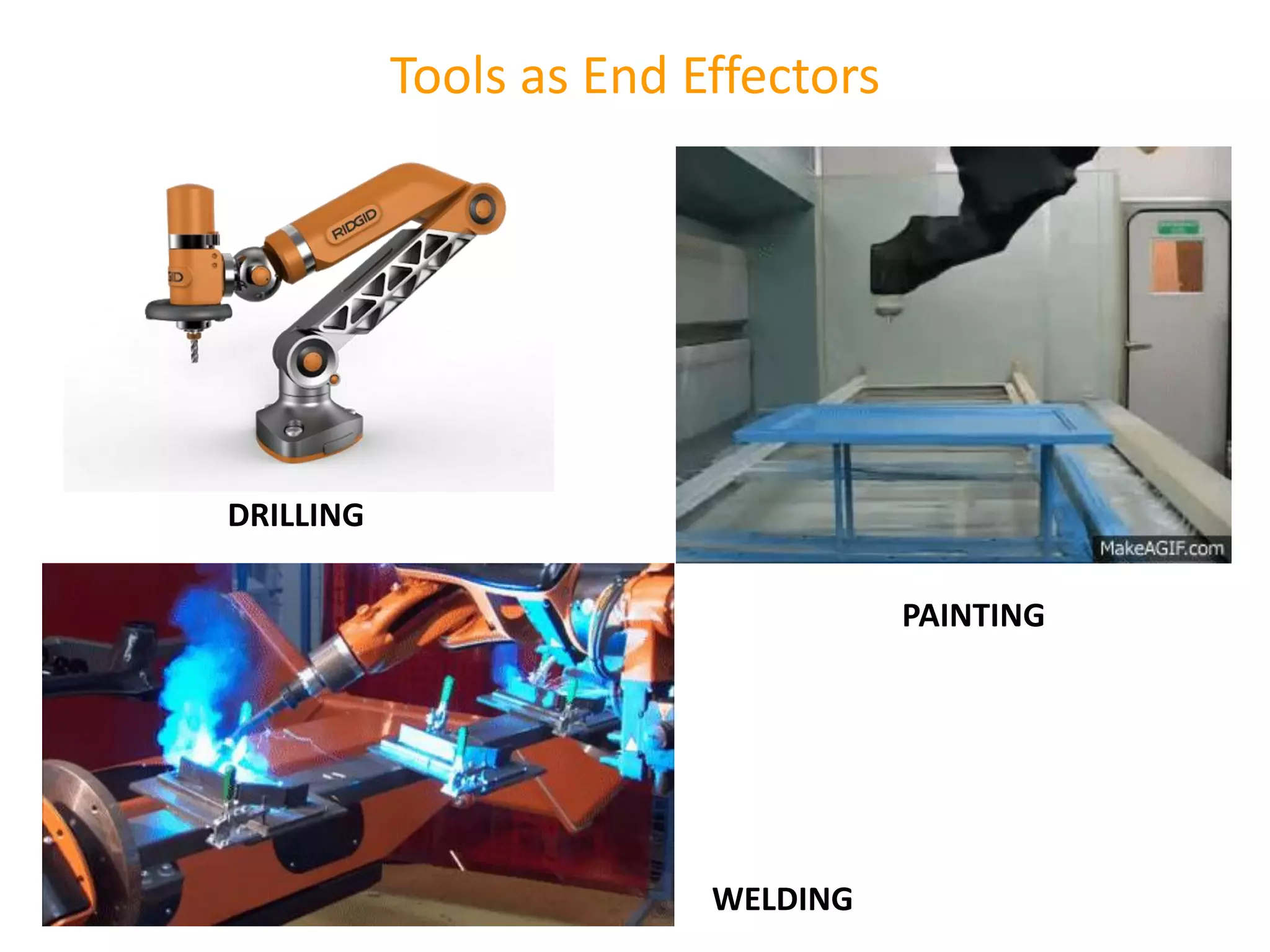
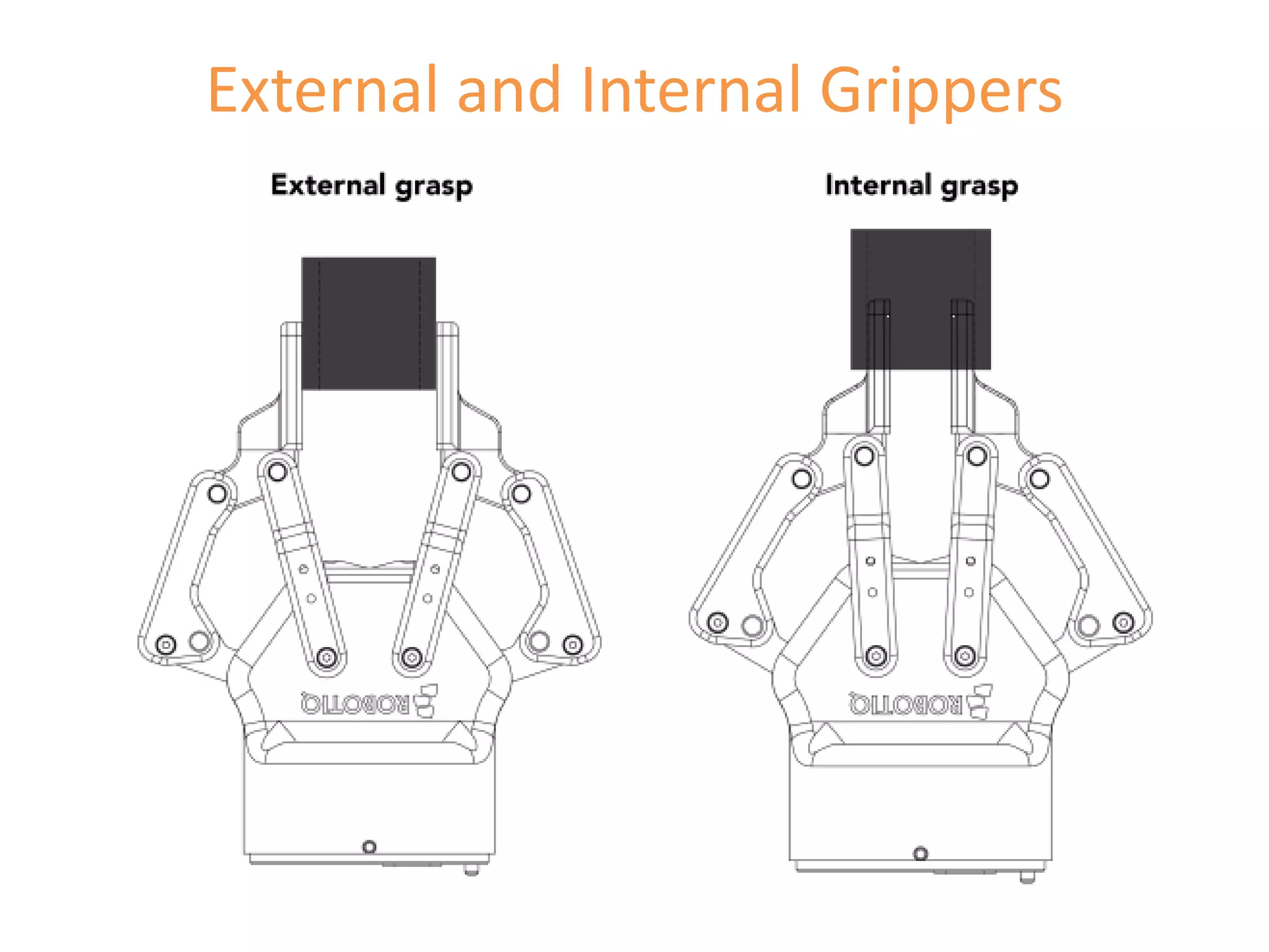
Discussion on end effectors, their types and functions, including grippers and specific tools for robotic applications.
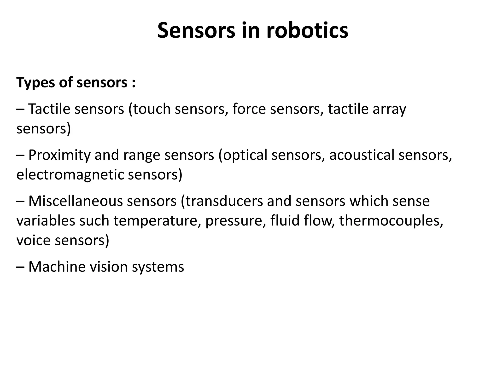
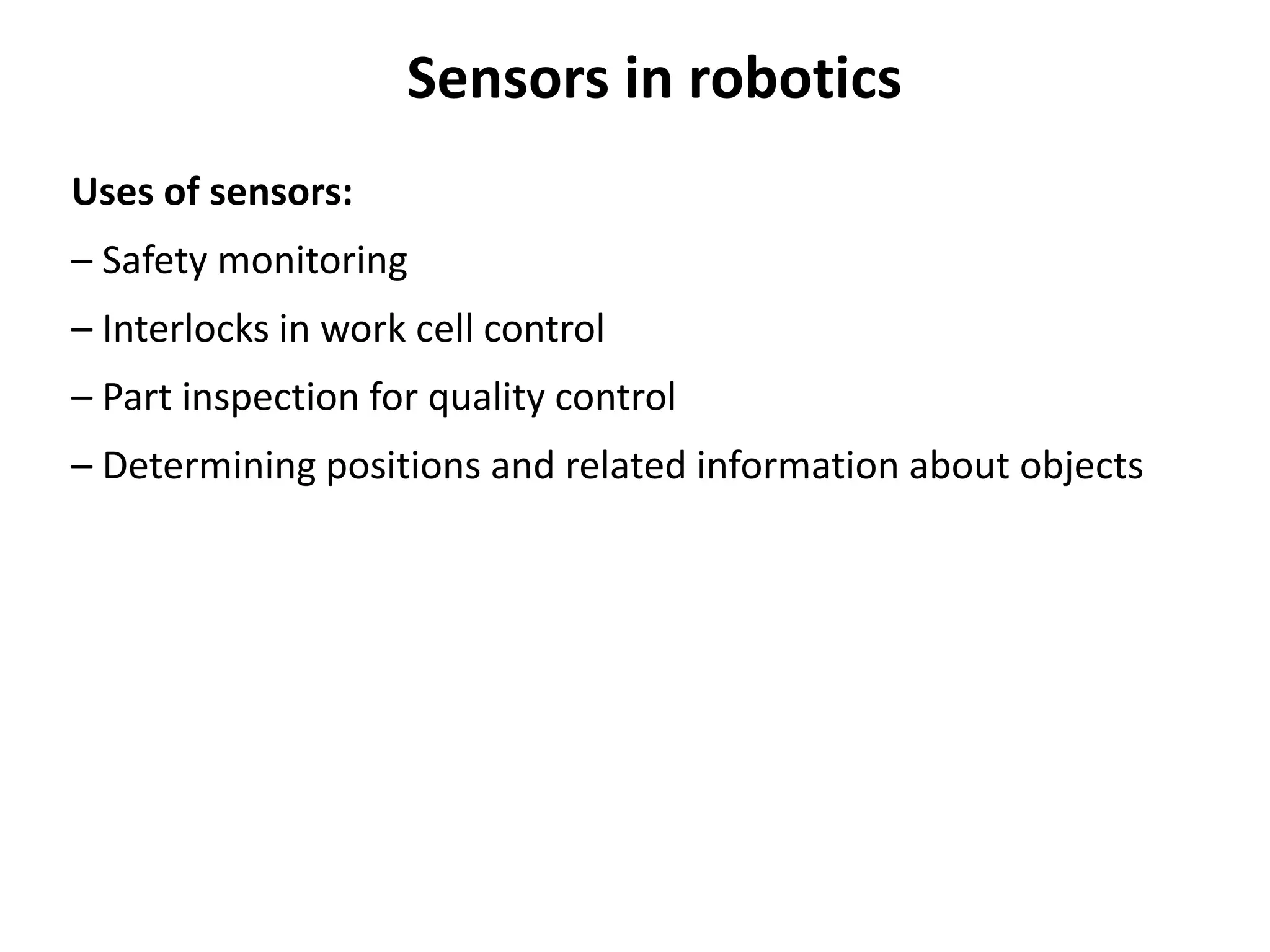
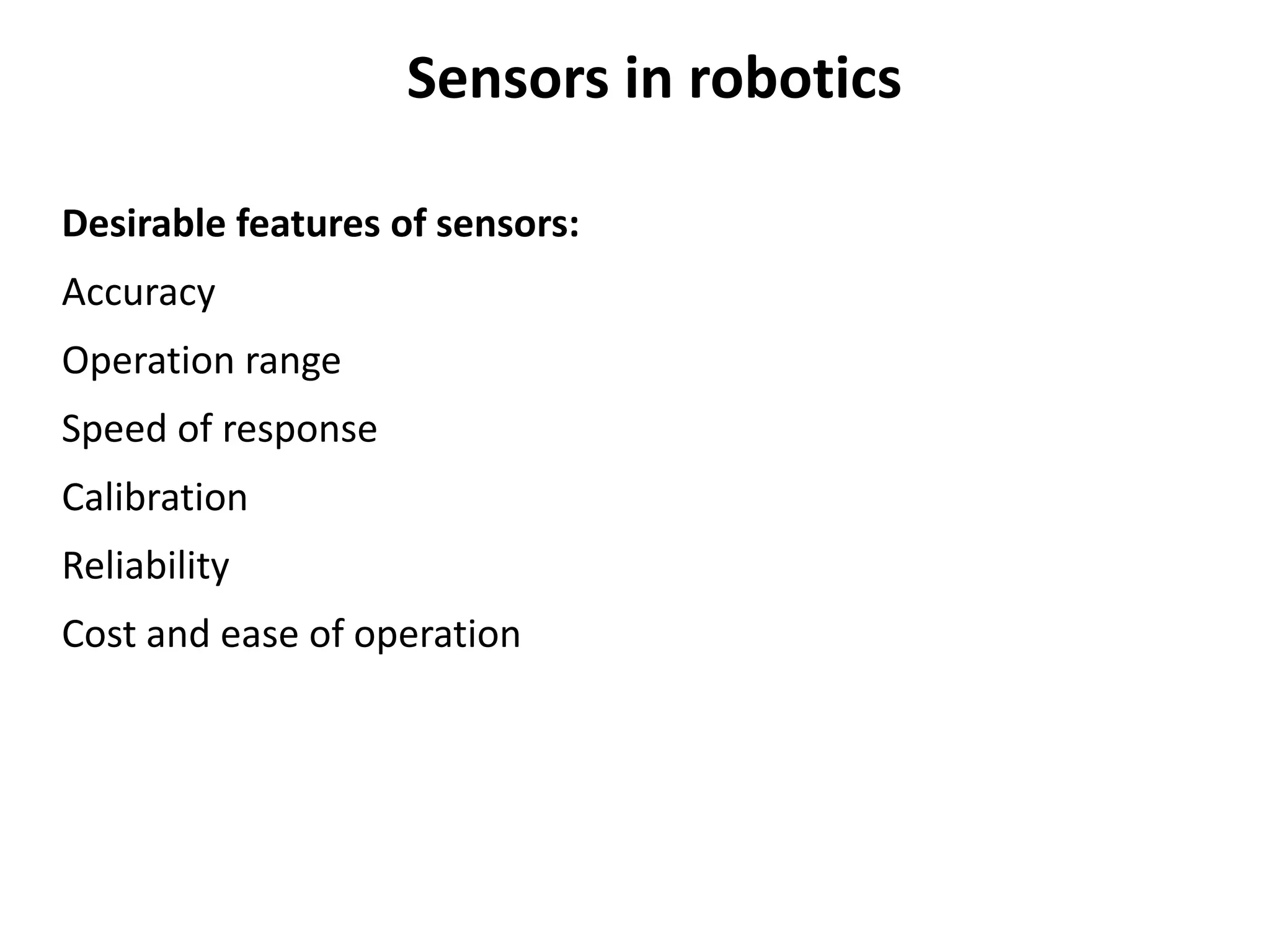
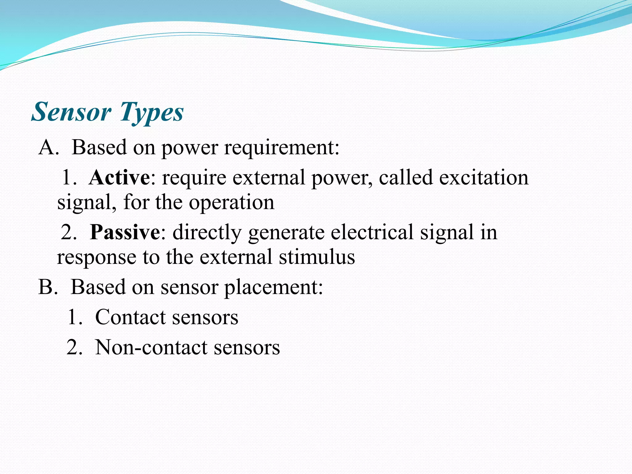
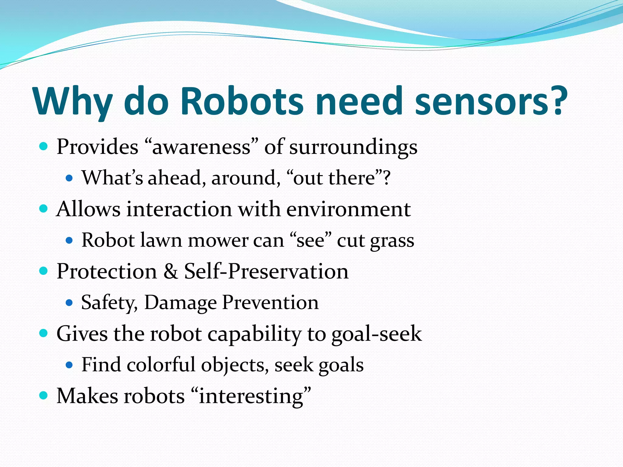
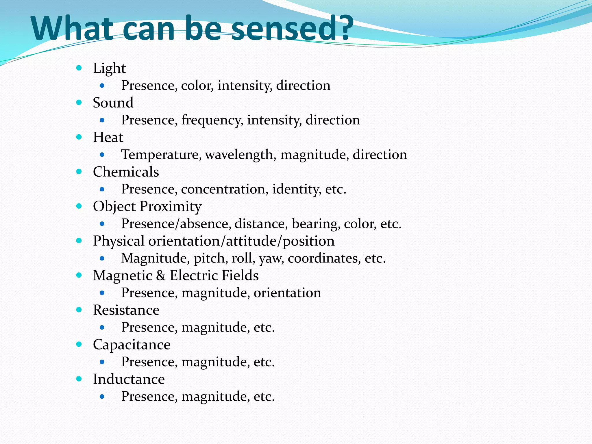
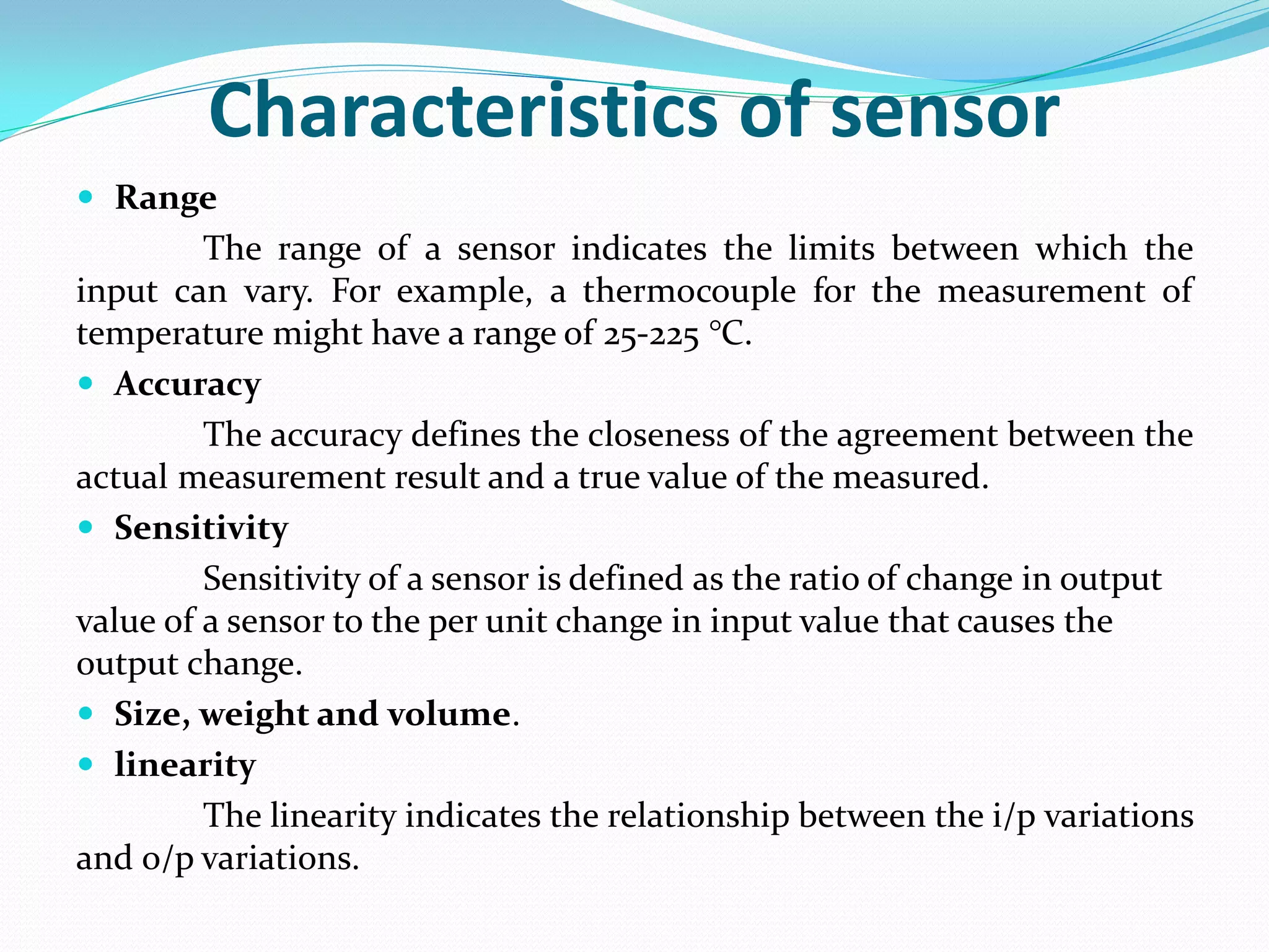
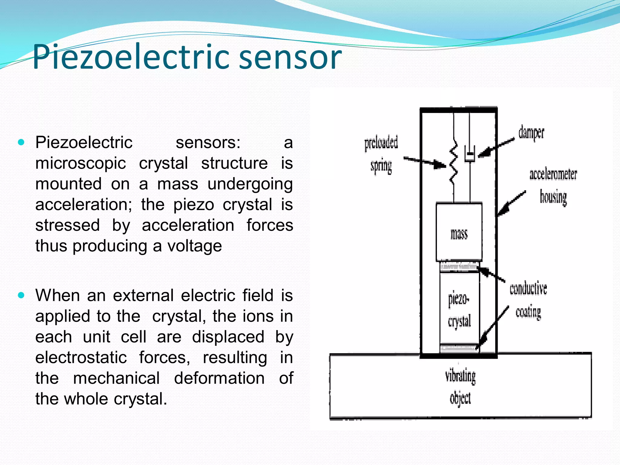
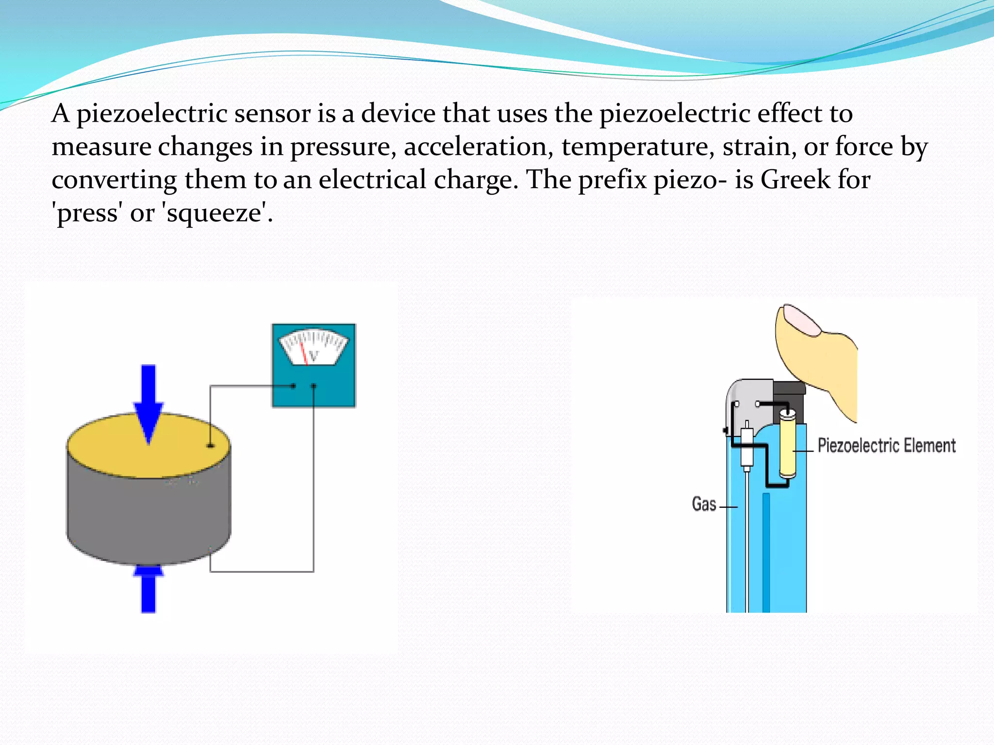
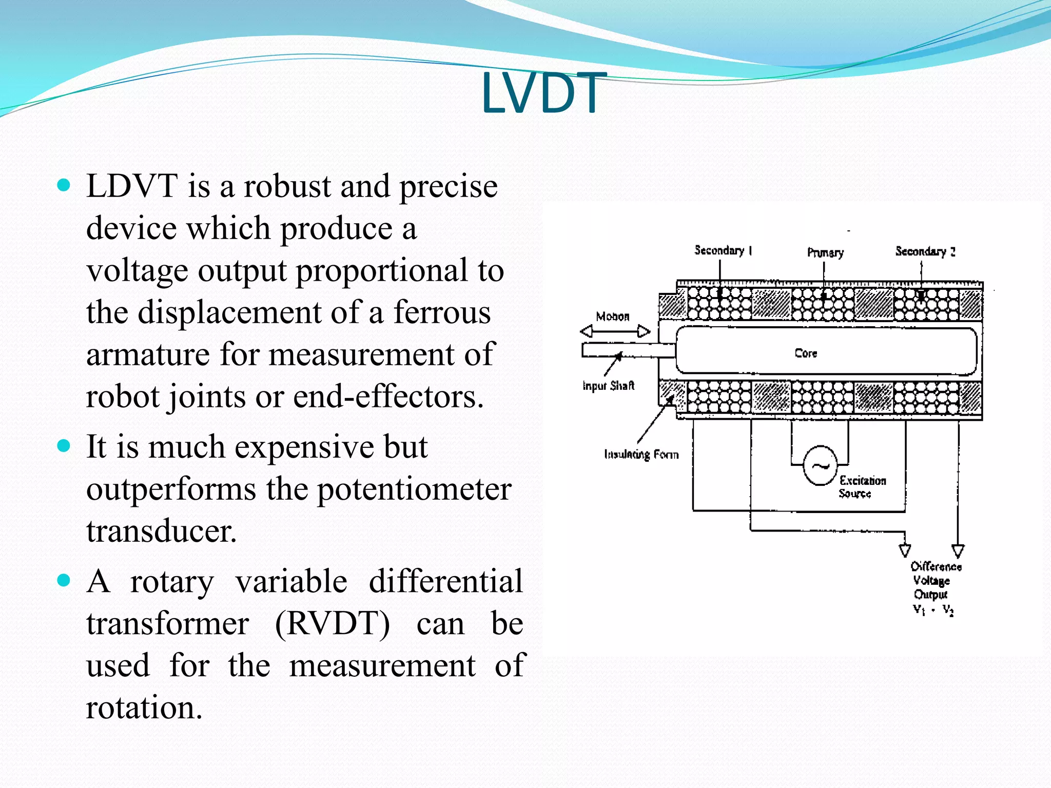
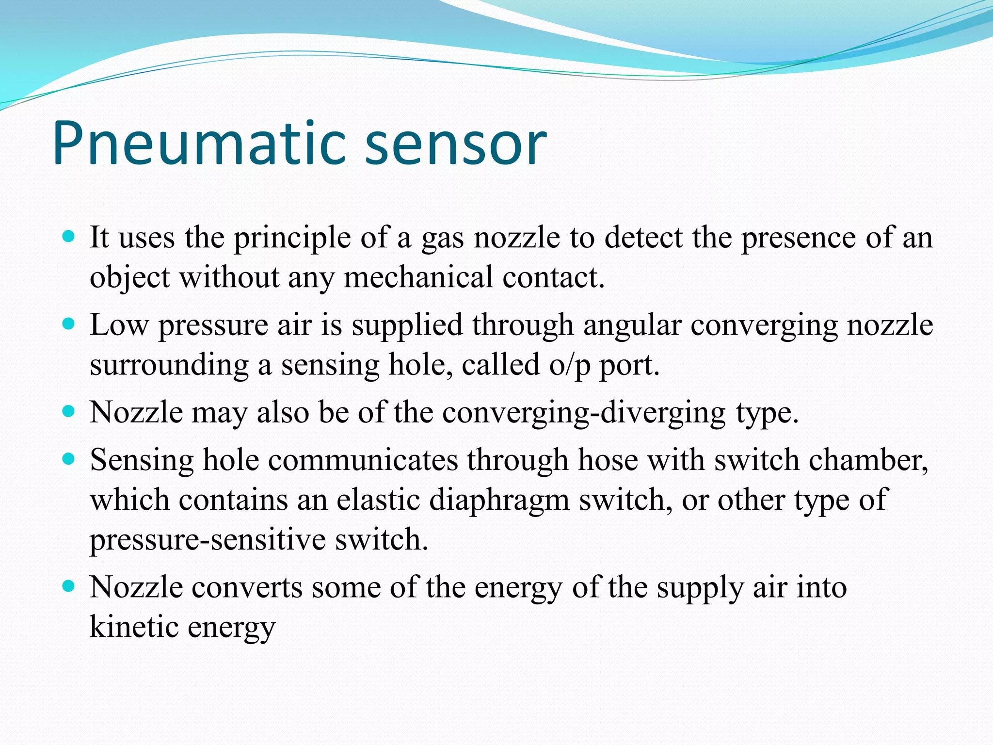
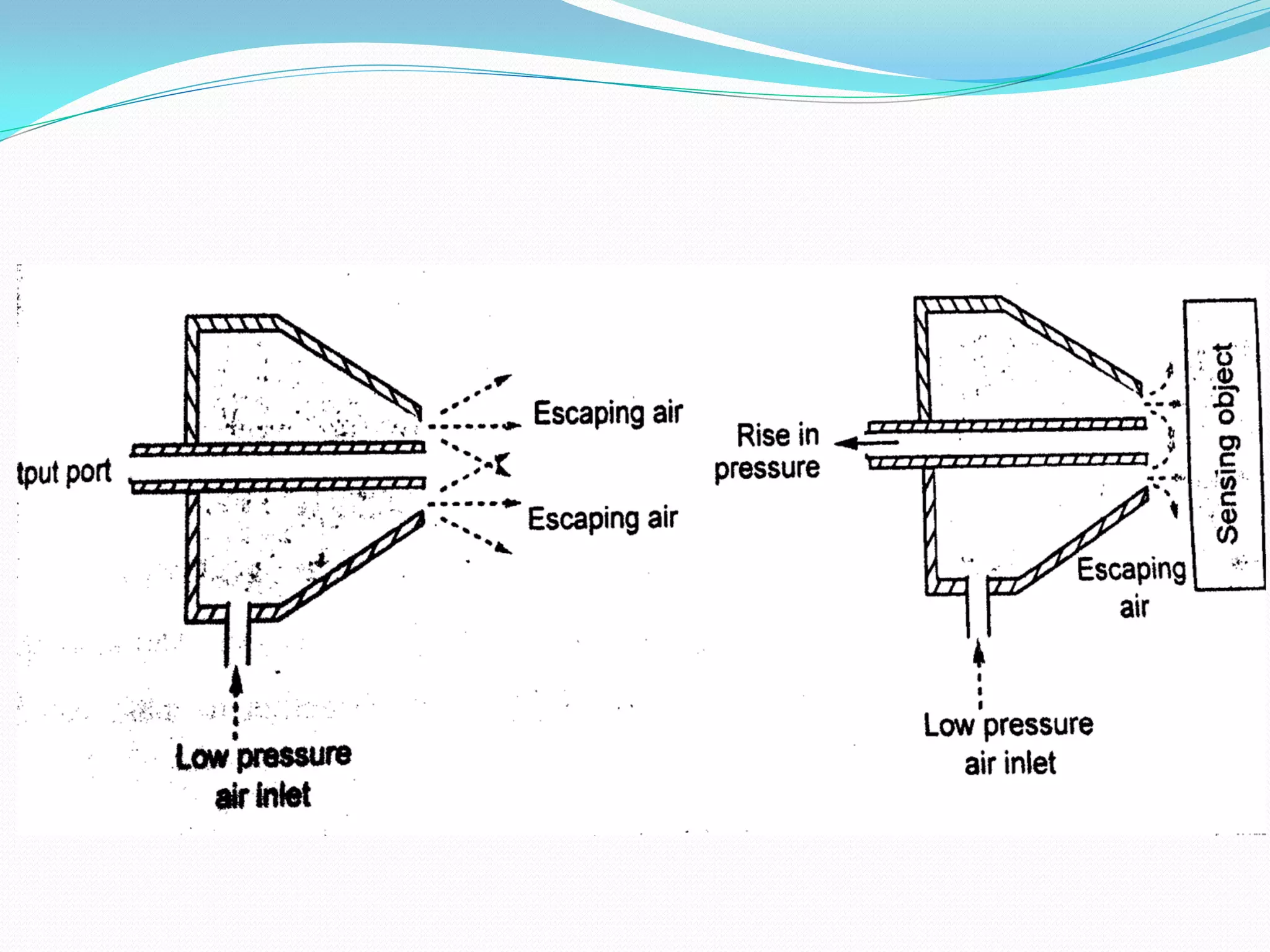
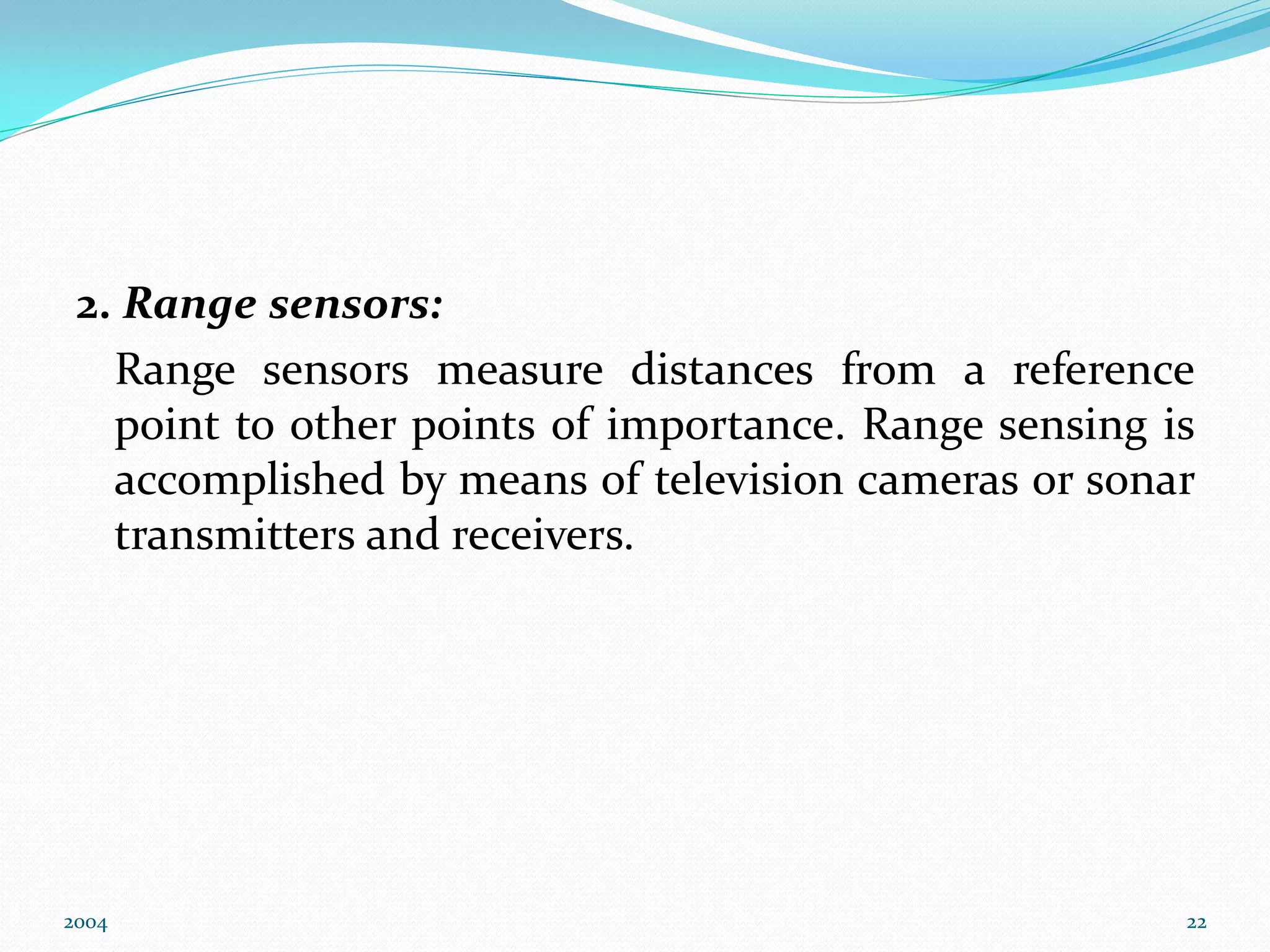
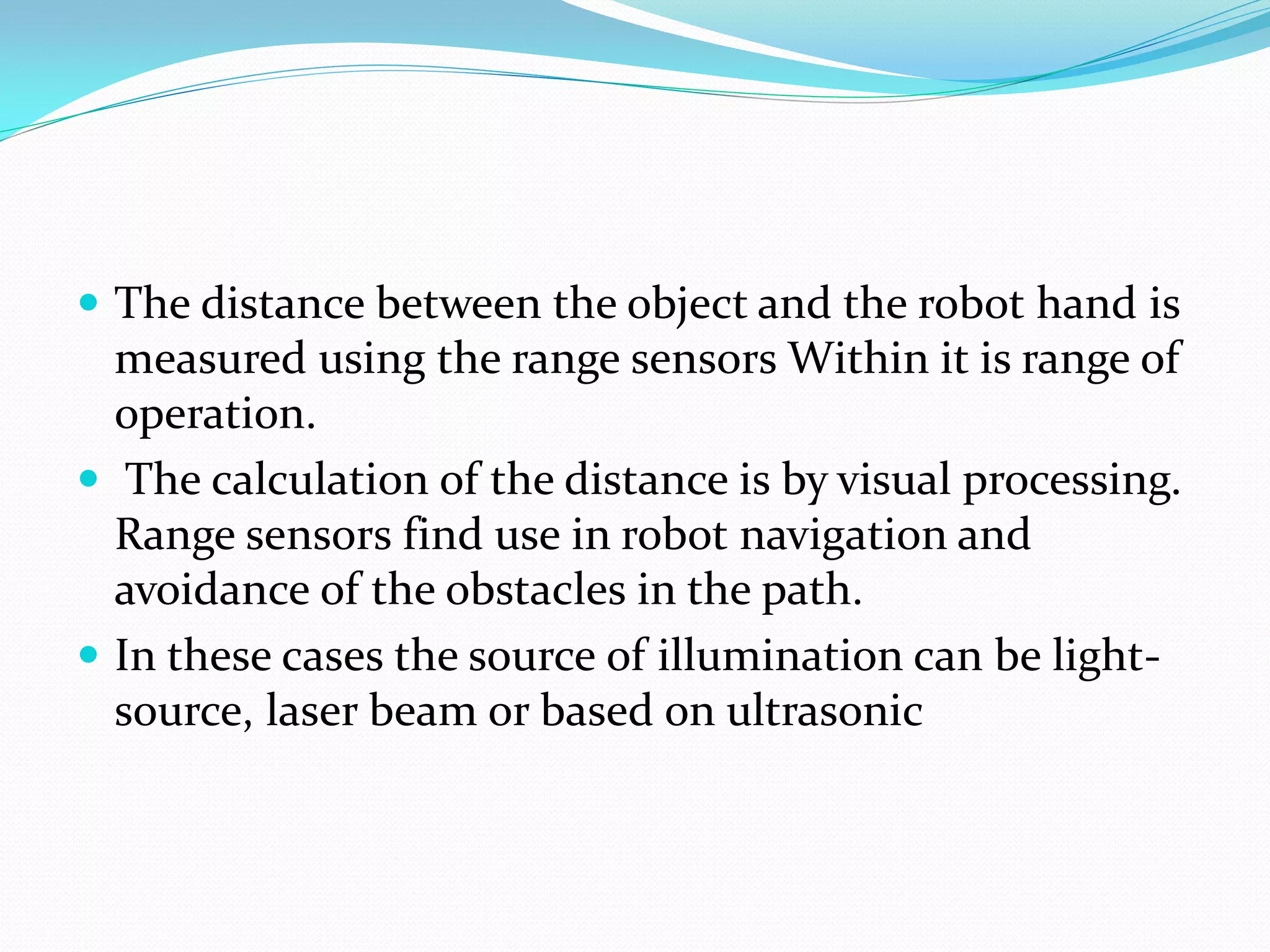
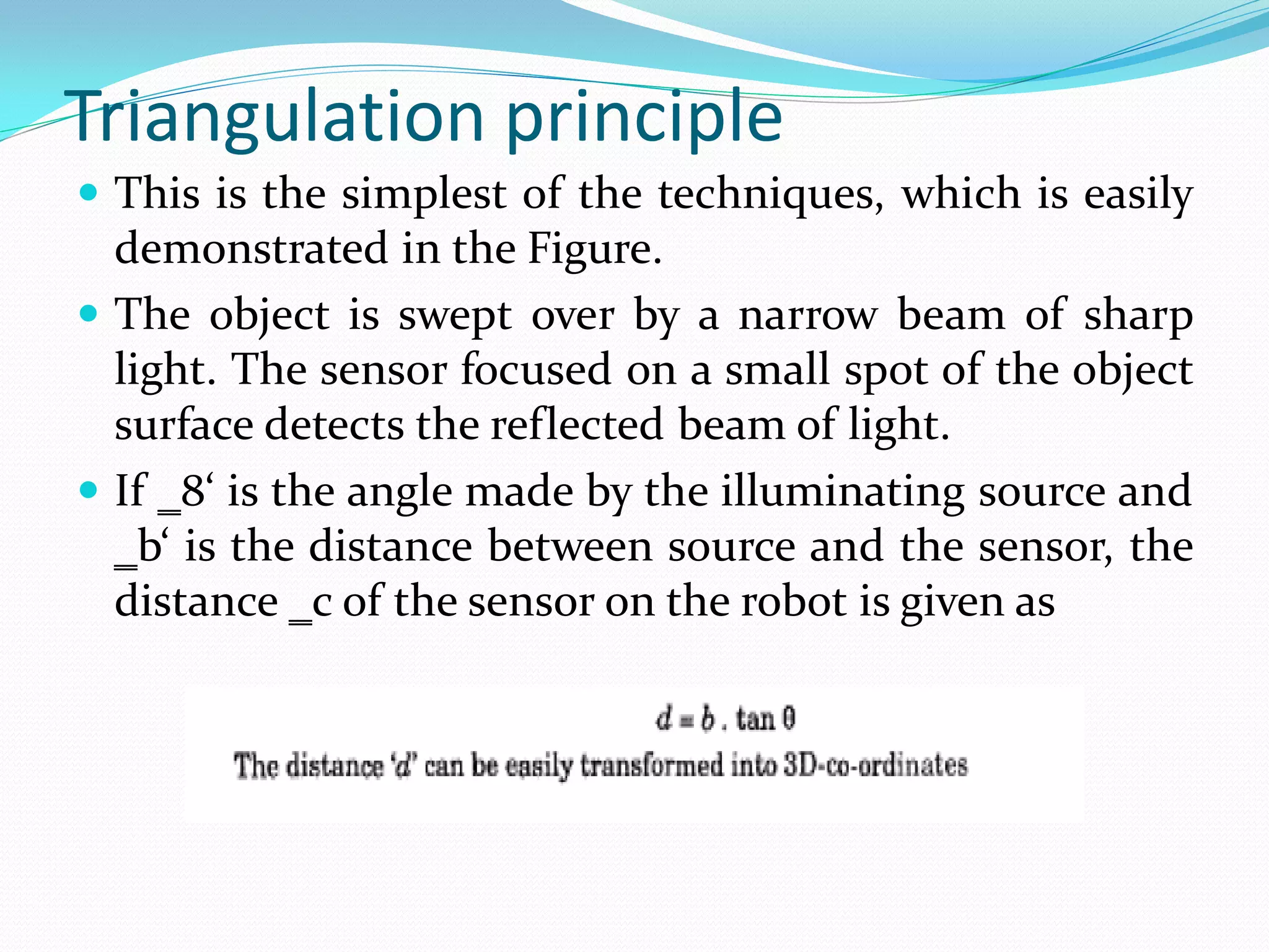
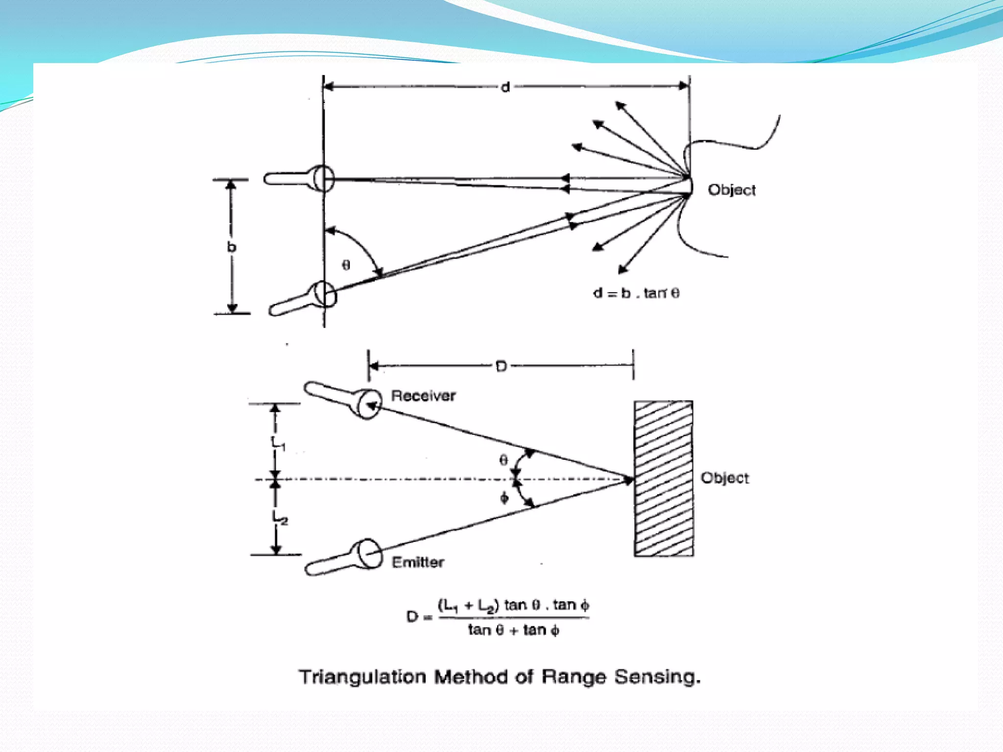
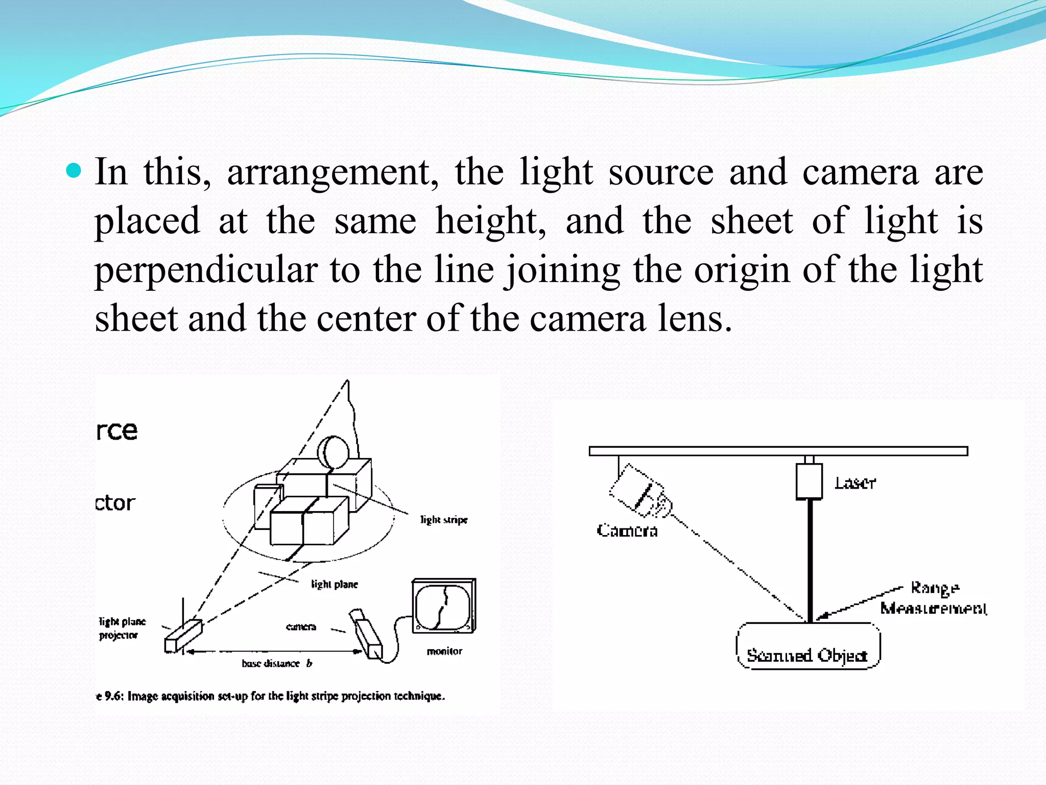
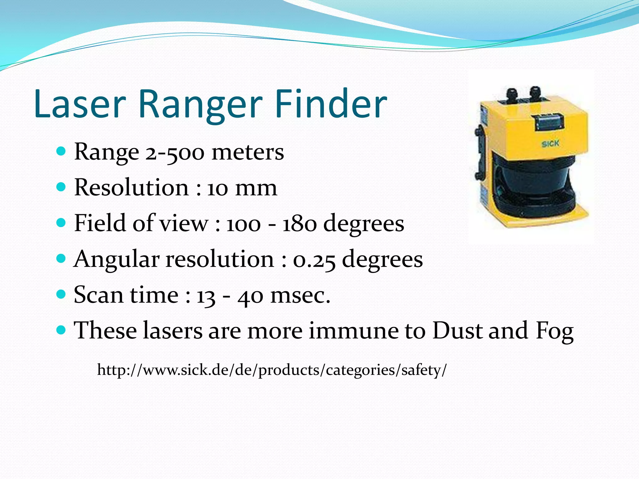
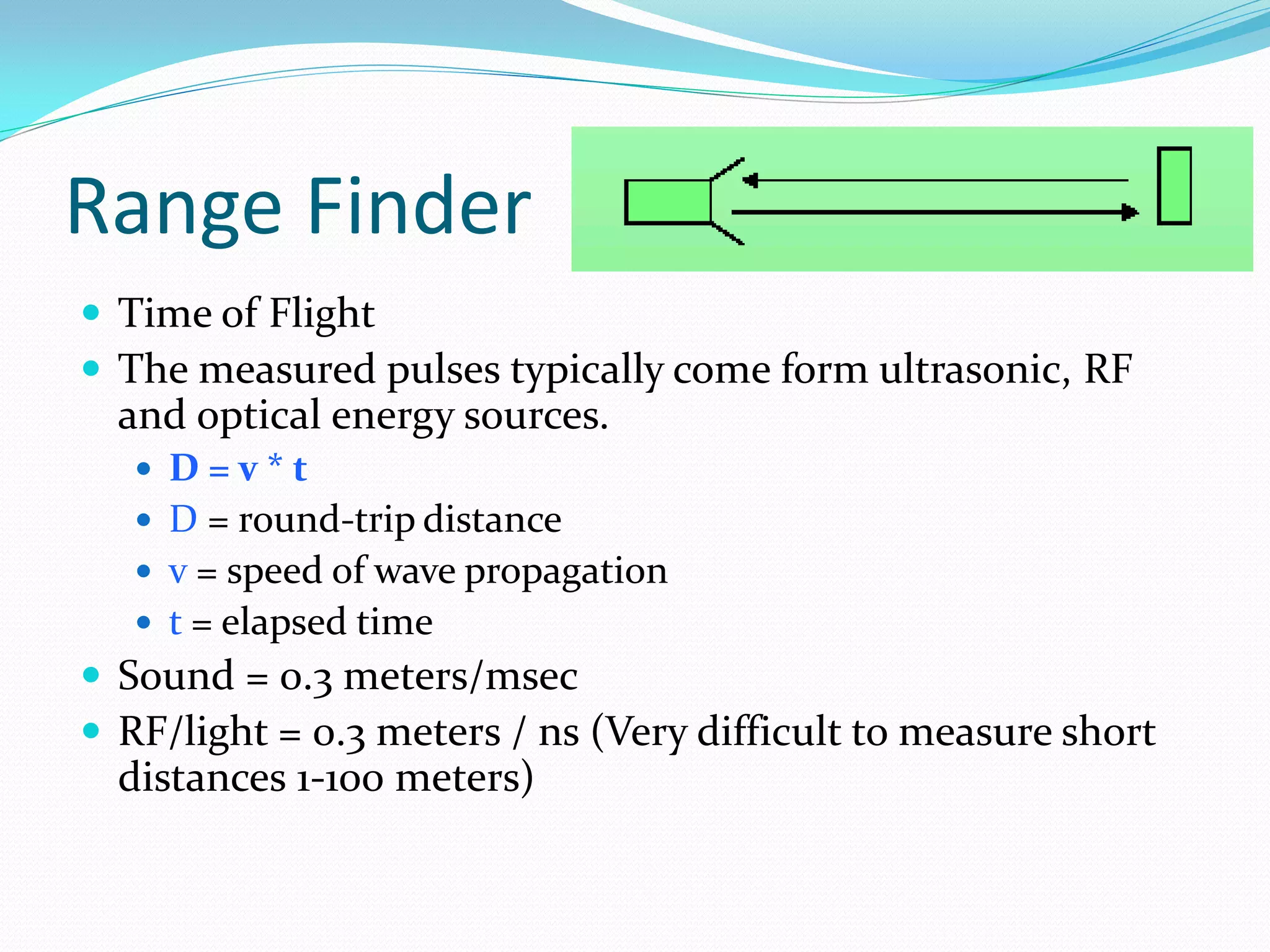
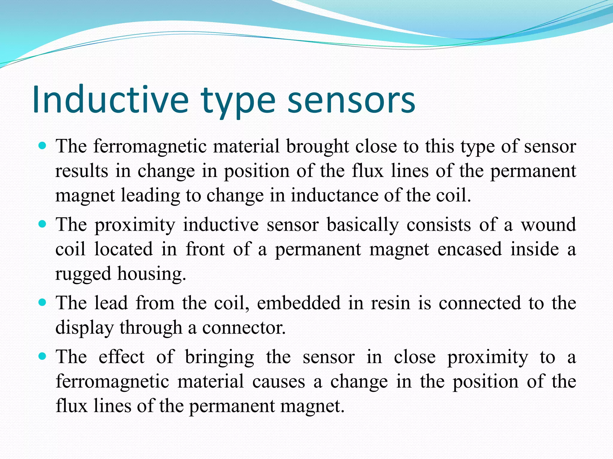
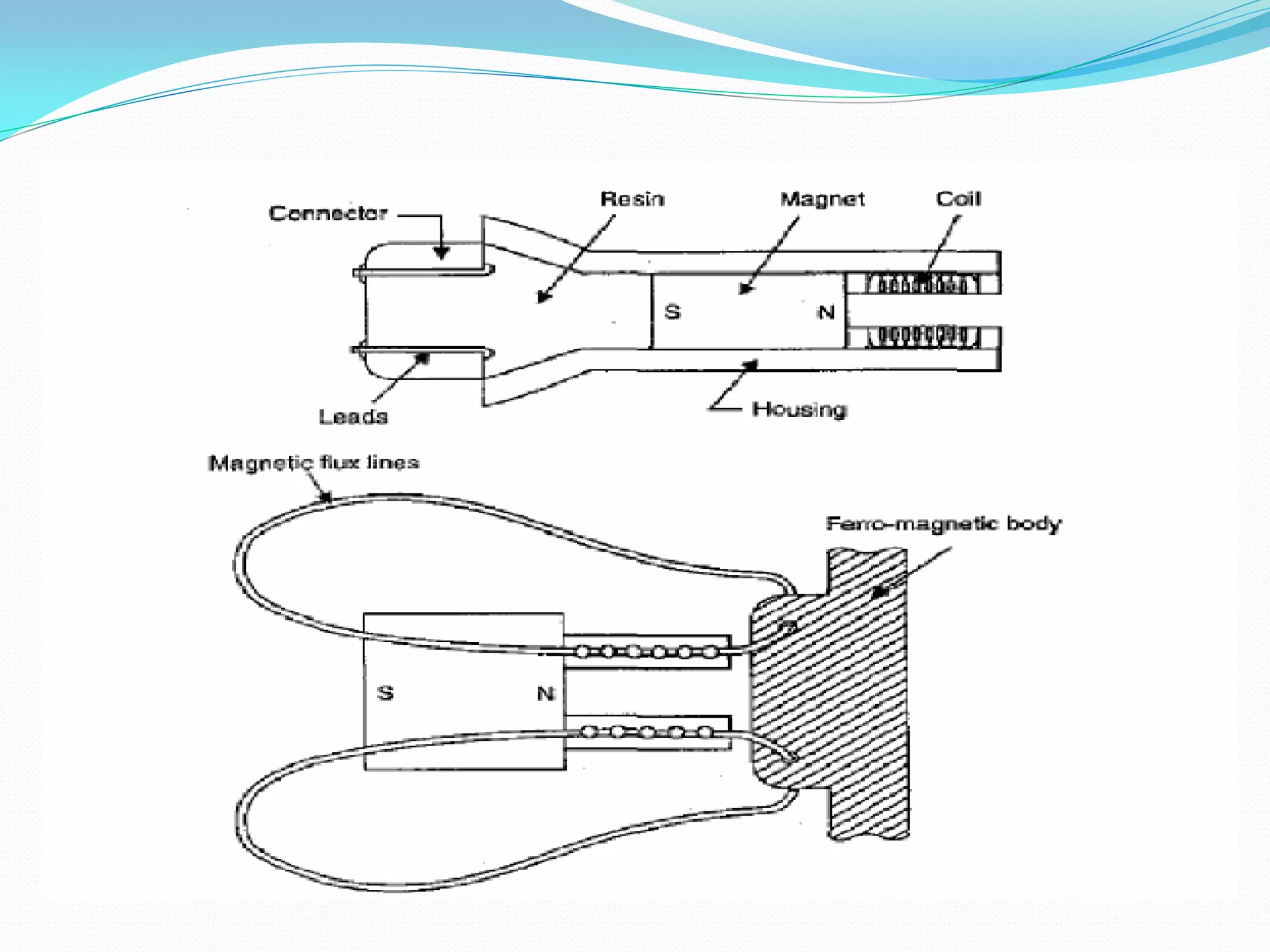
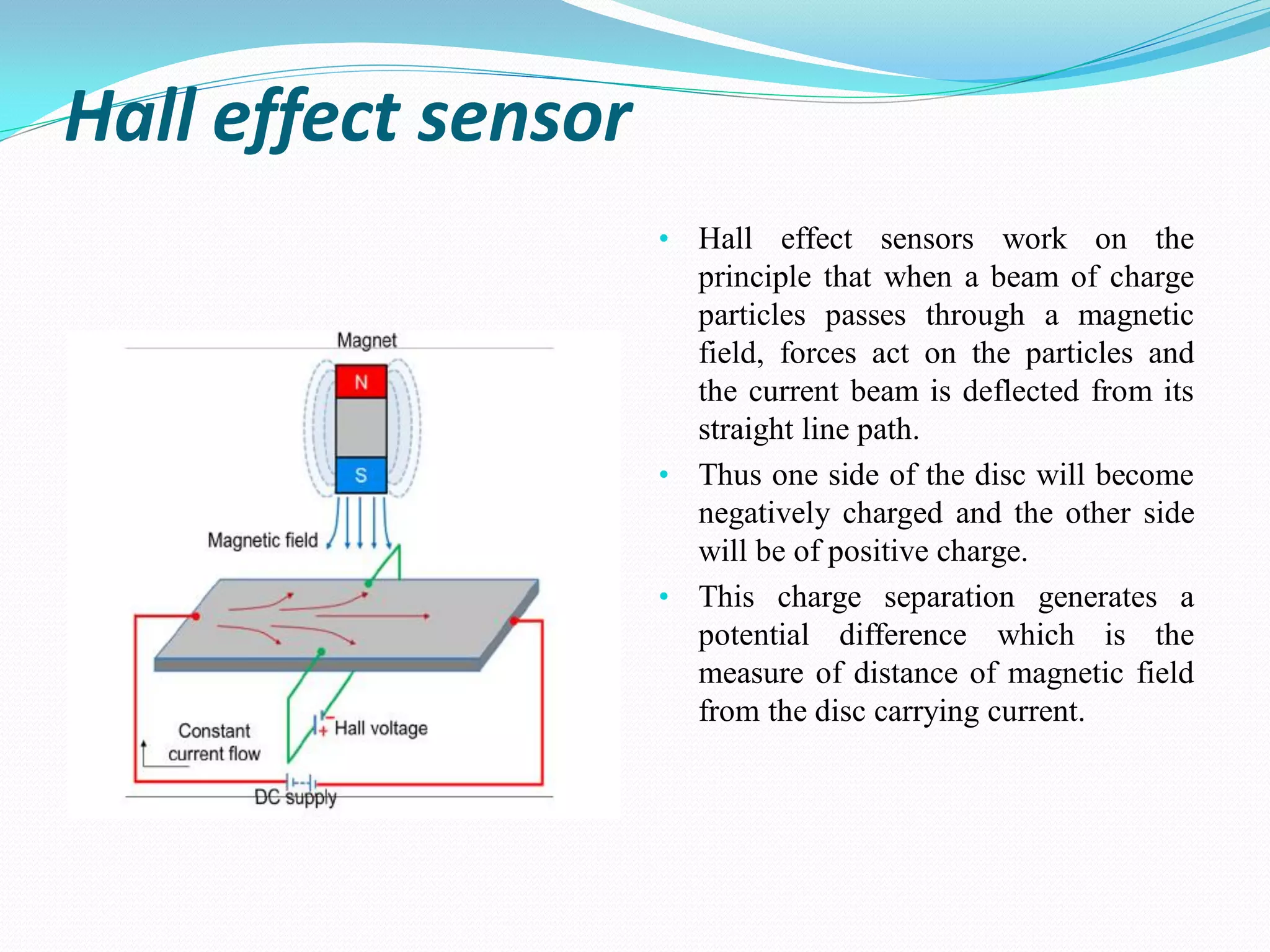
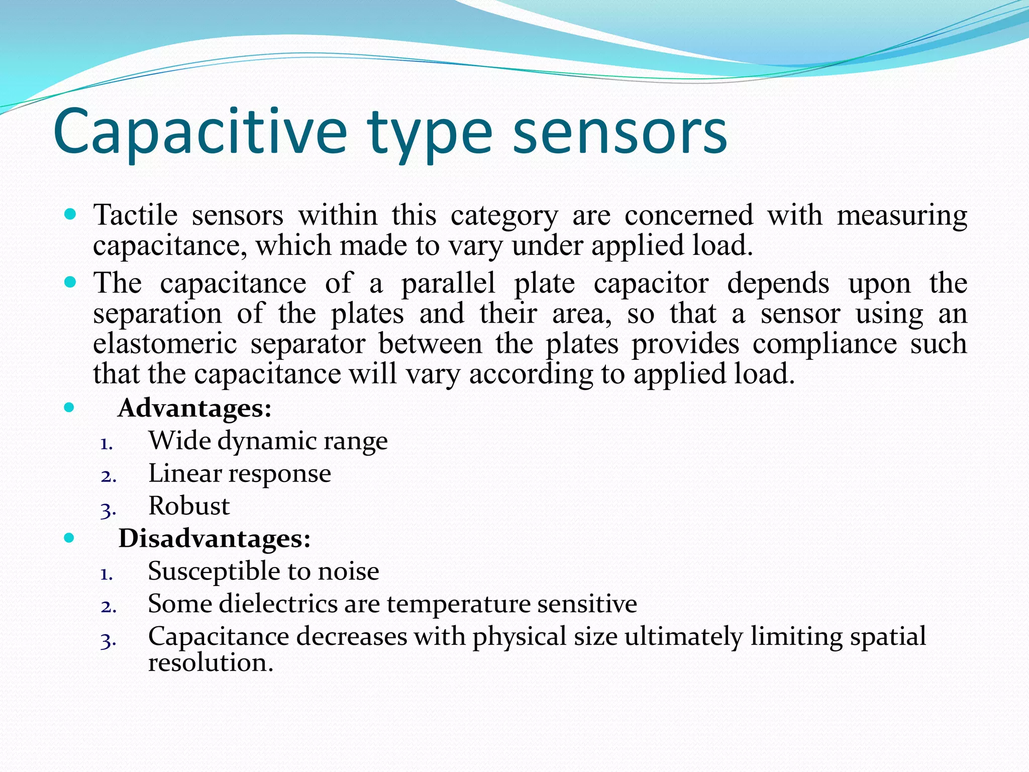
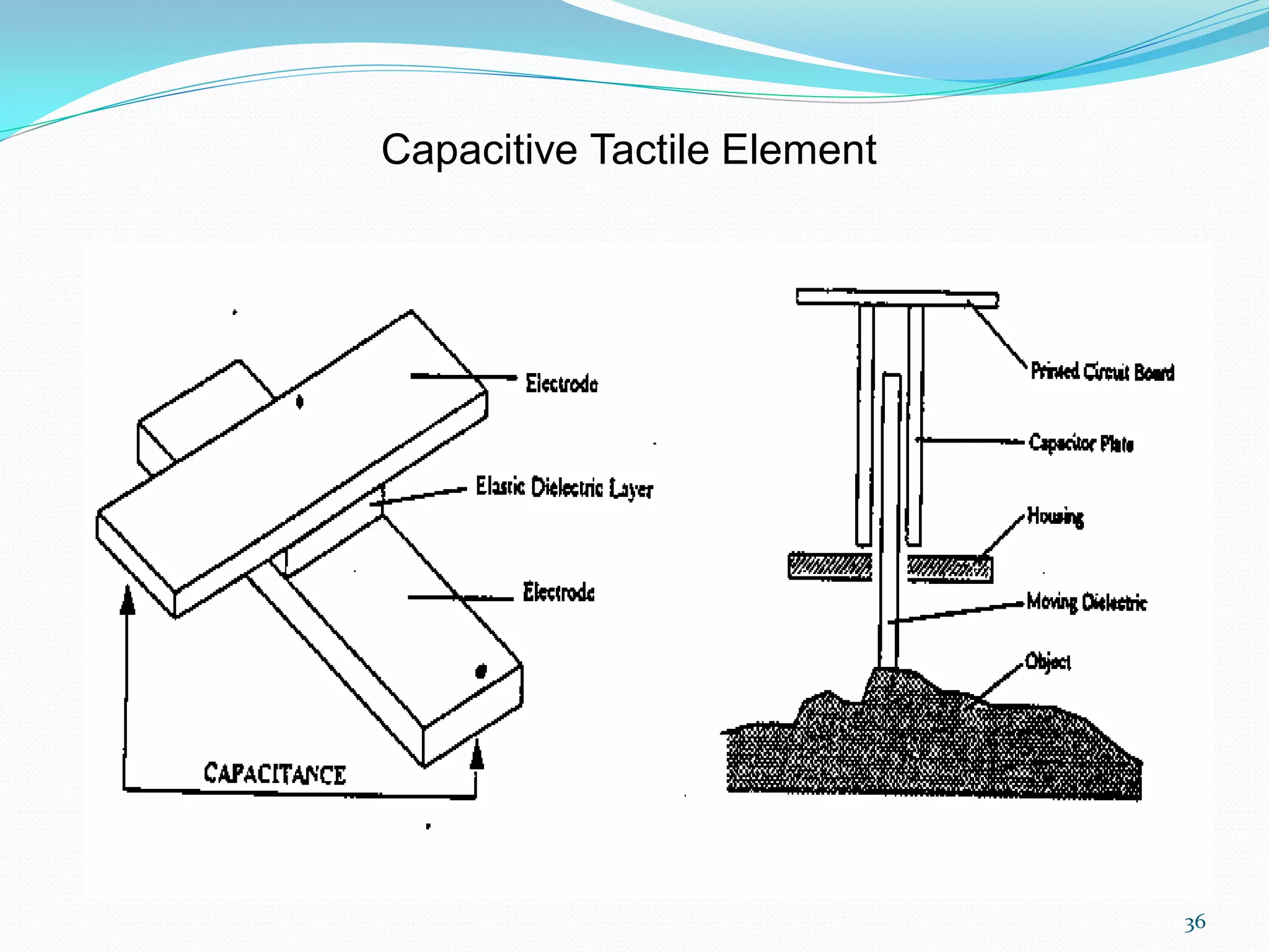
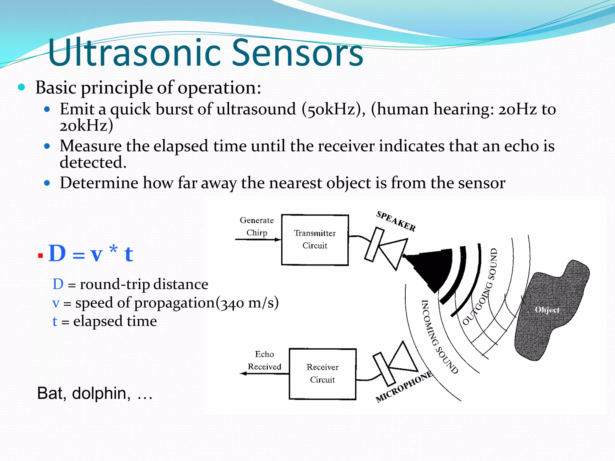
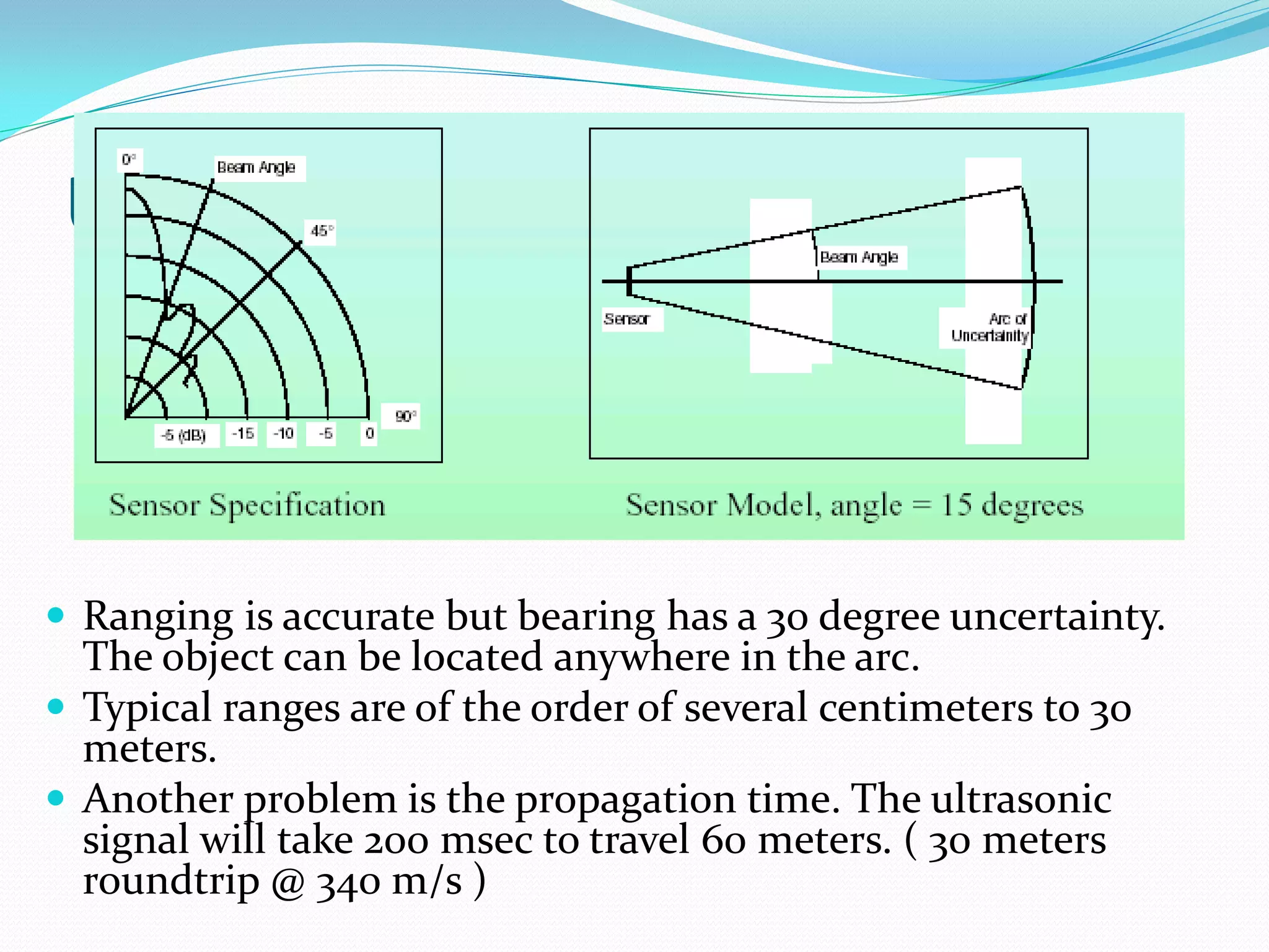
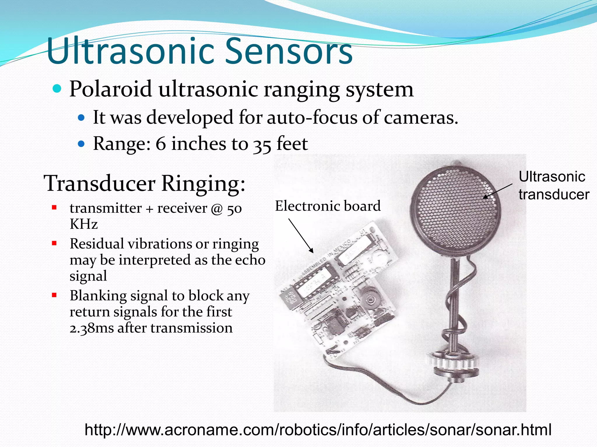
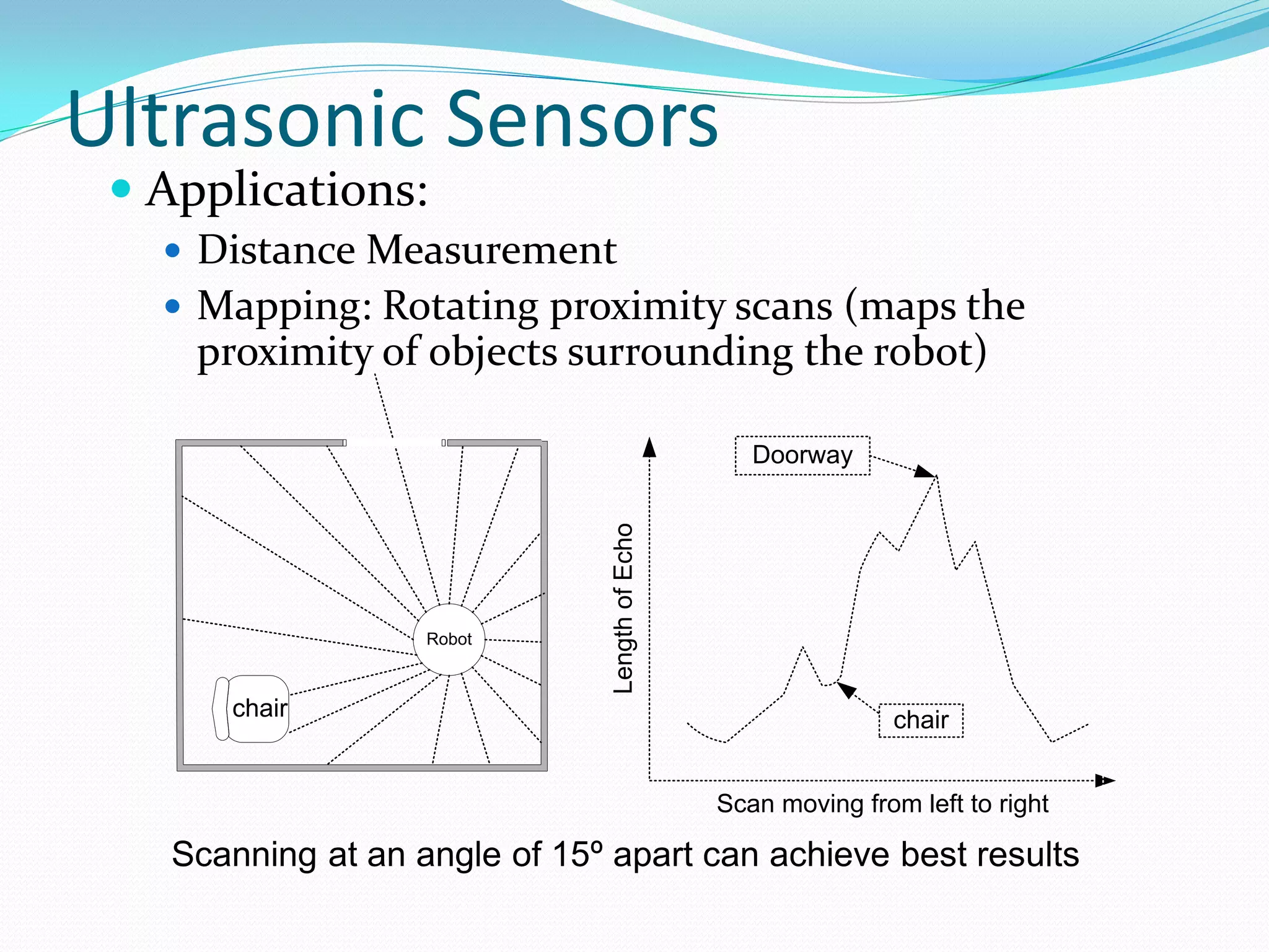
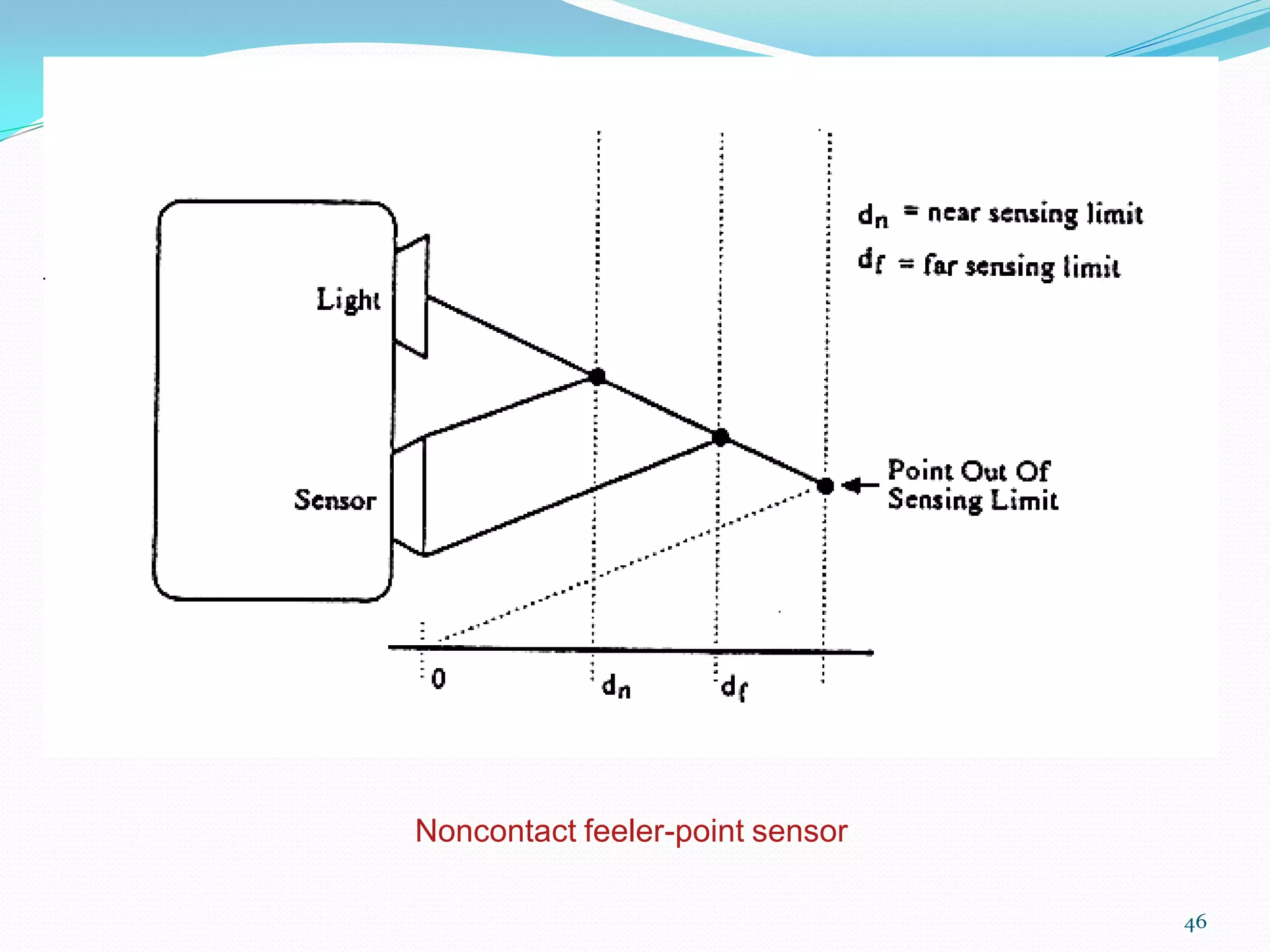
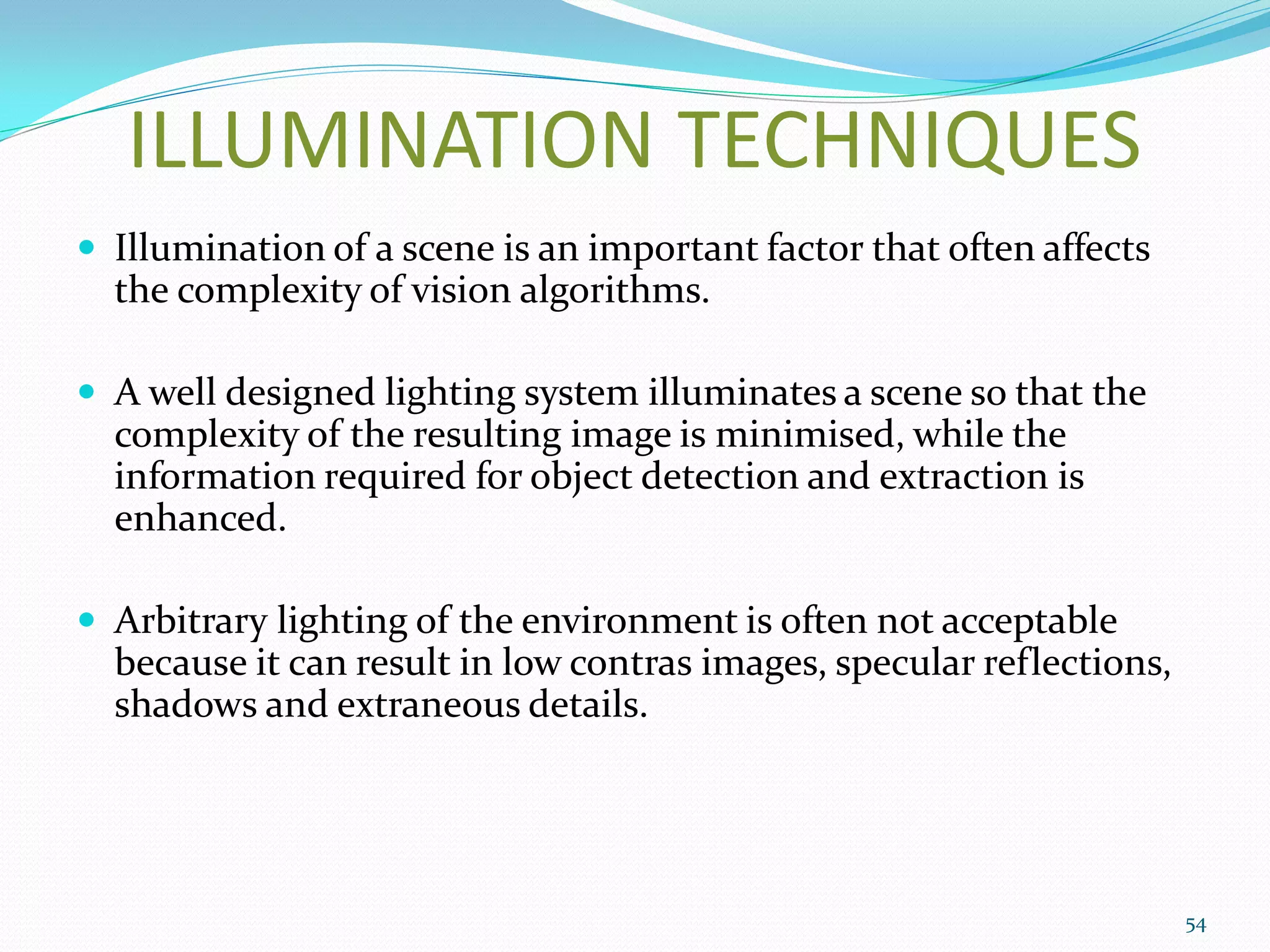
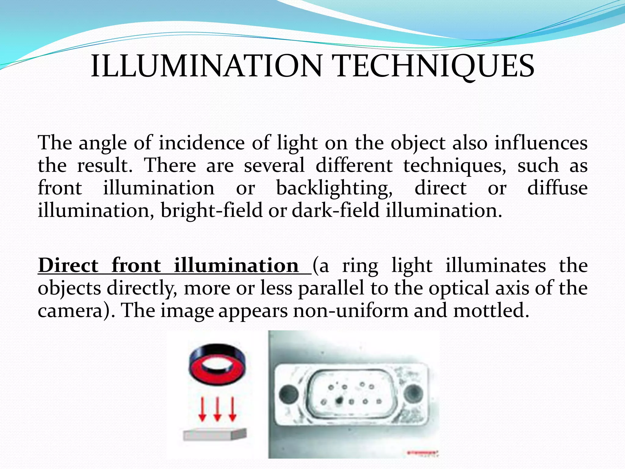
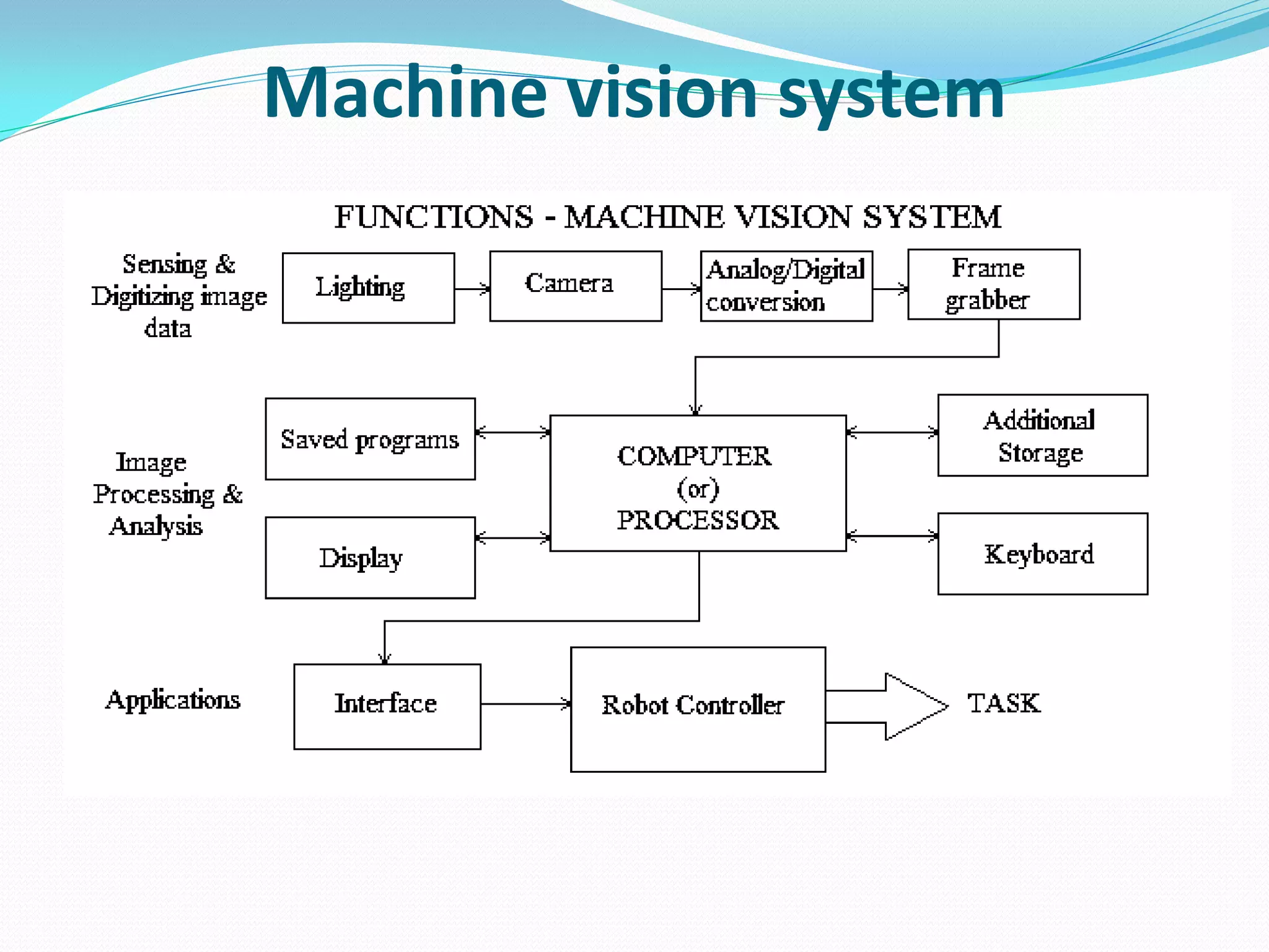
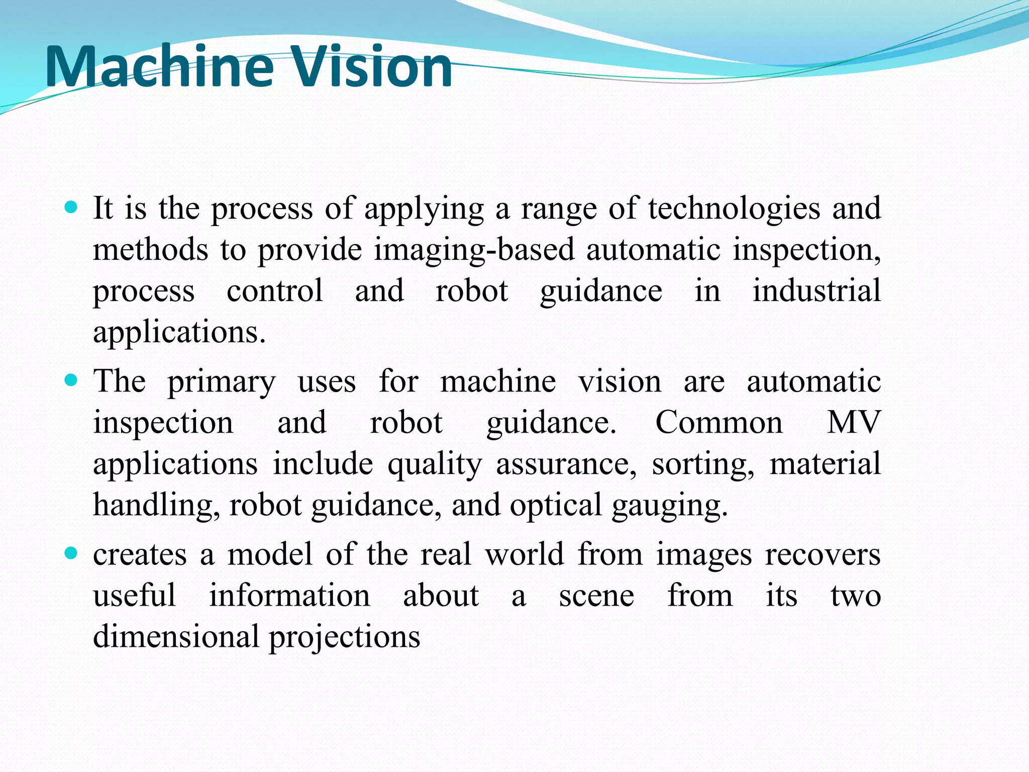
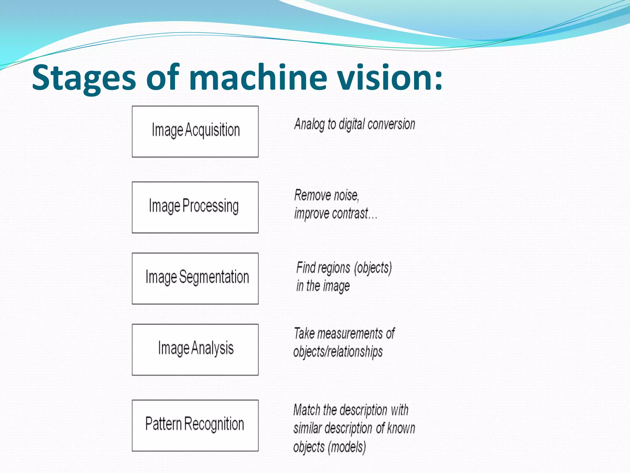
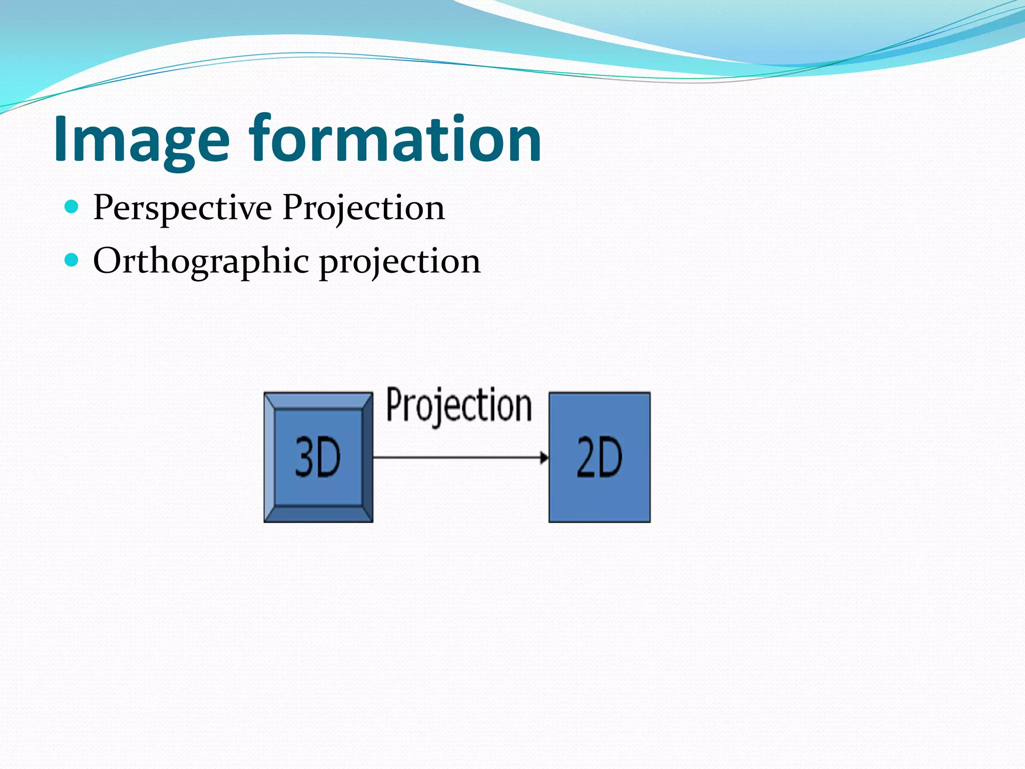
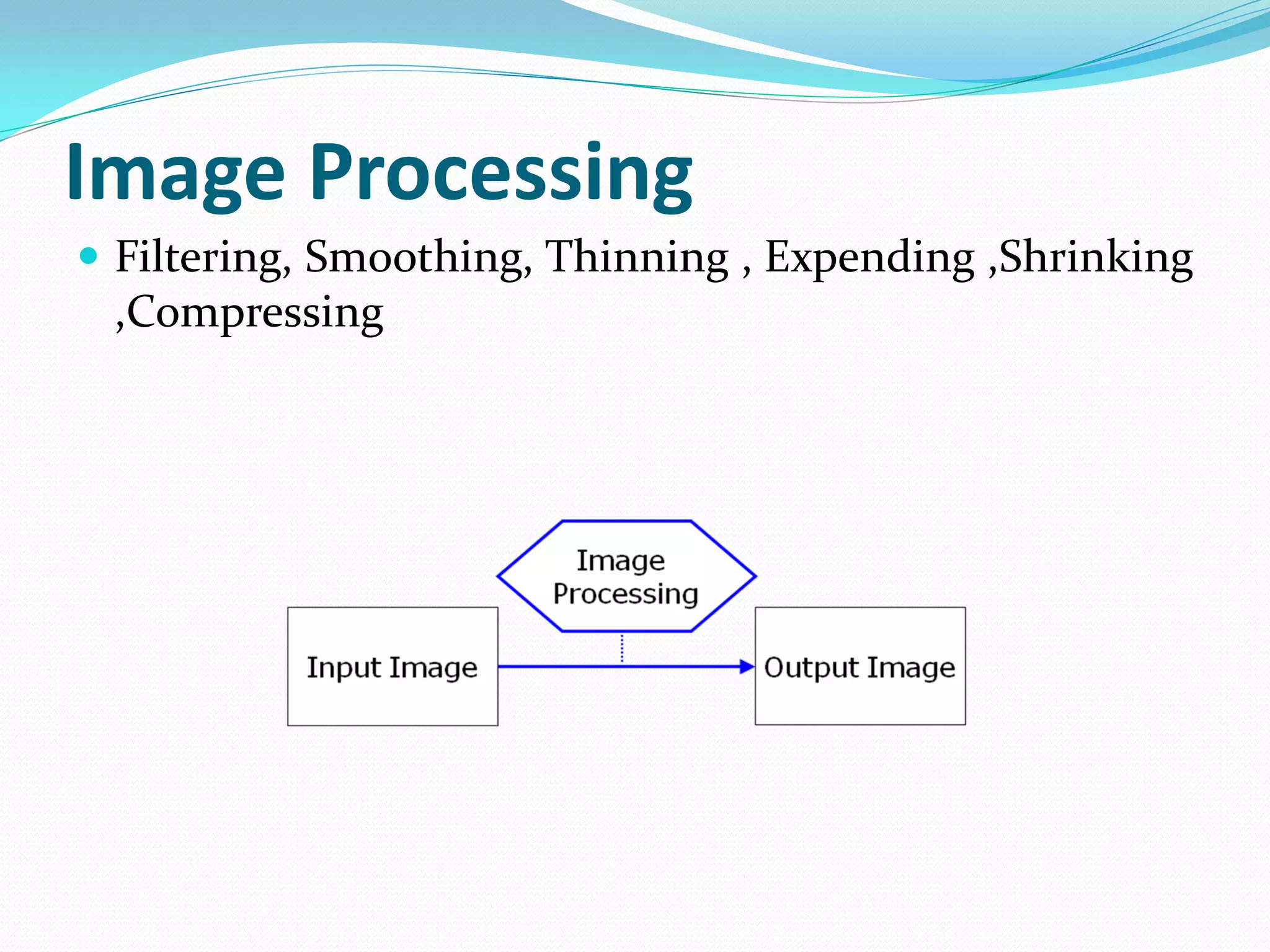
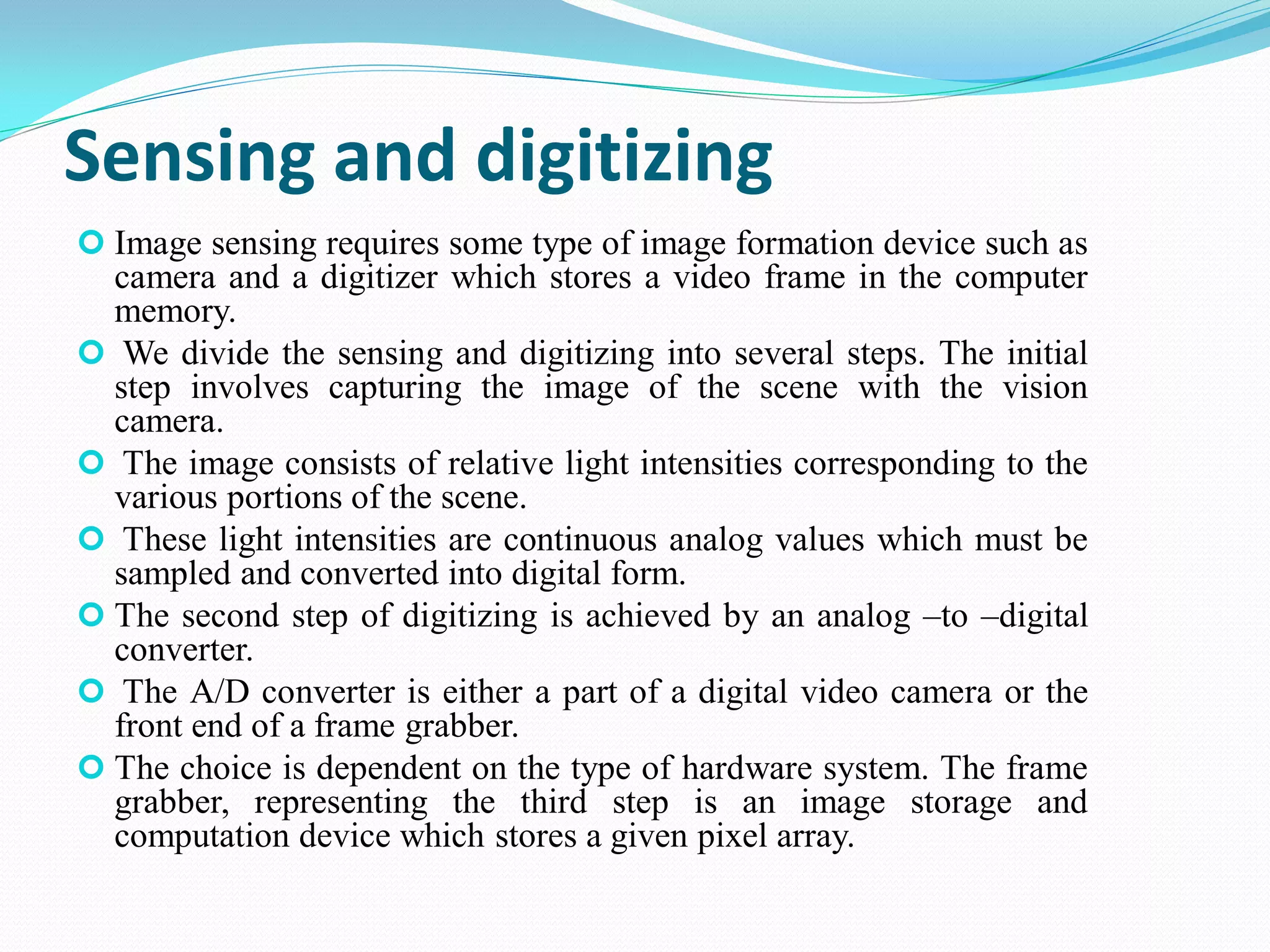
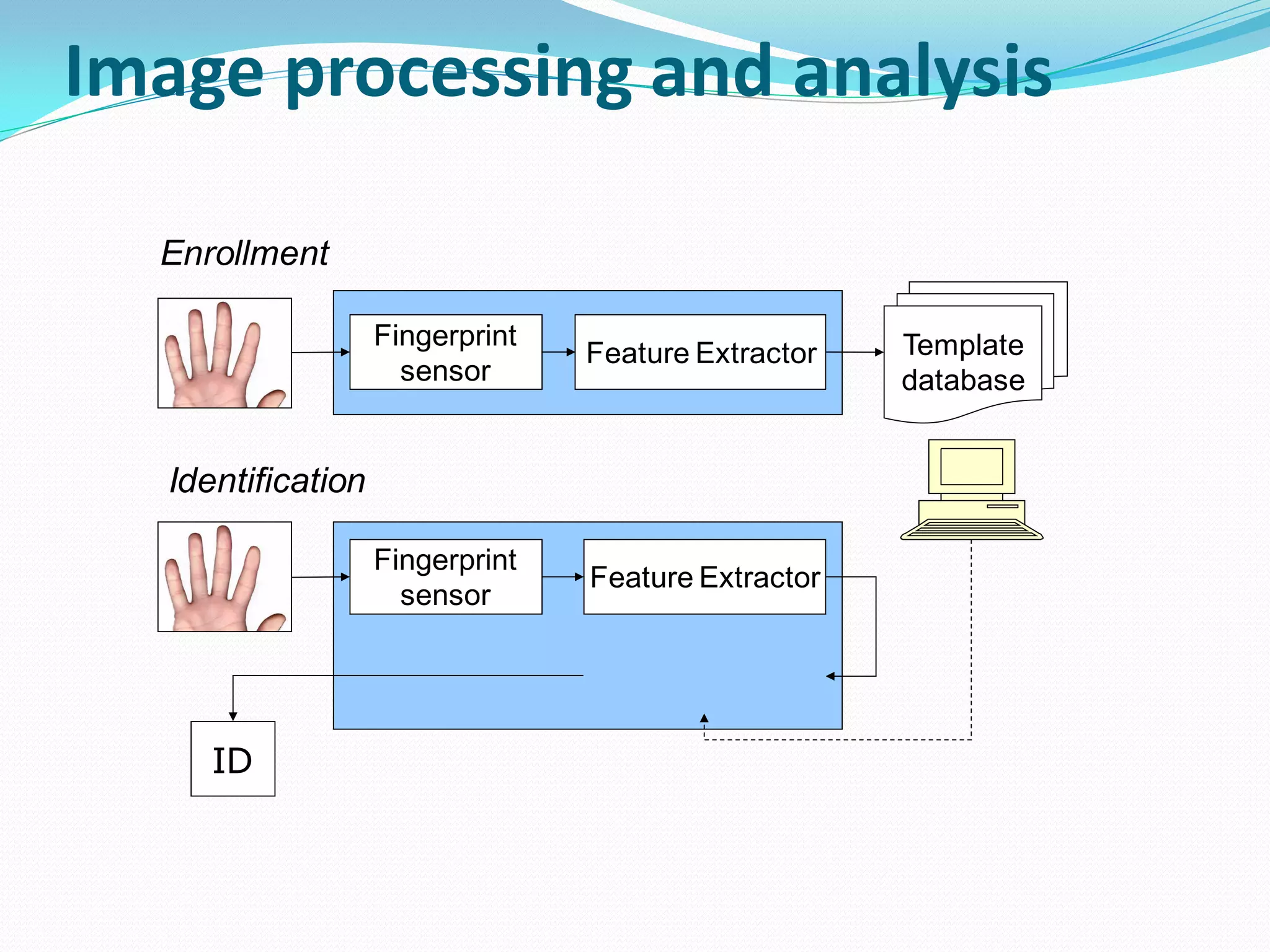
Exploration of robotic sensors, classification by function, and machine vision systems for environmental interaction.