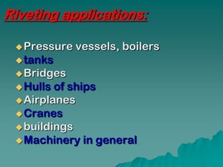
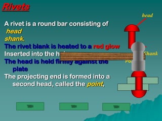
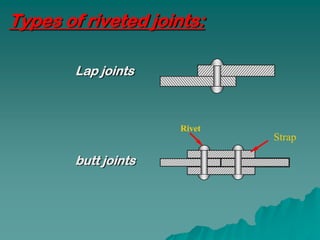
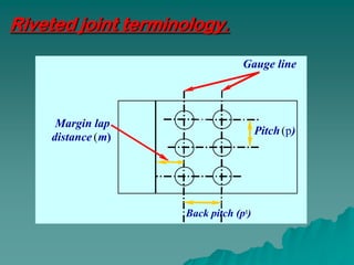
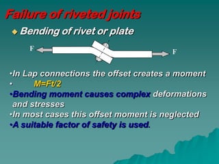
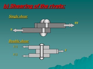
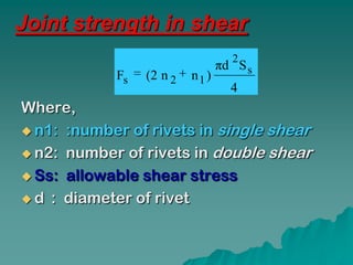
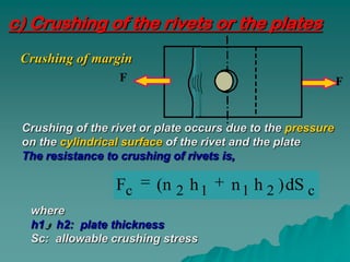
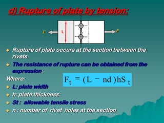
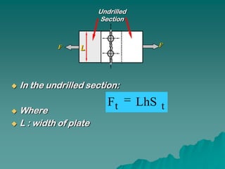
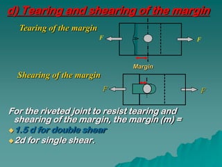
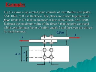
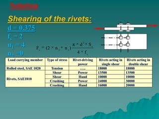
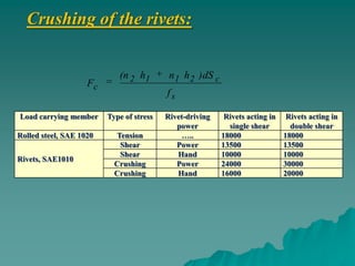
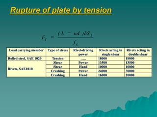
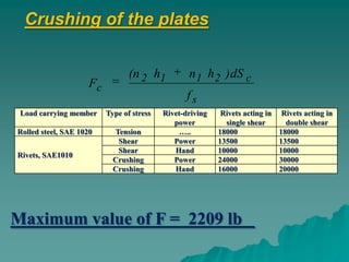
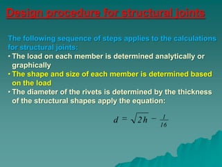
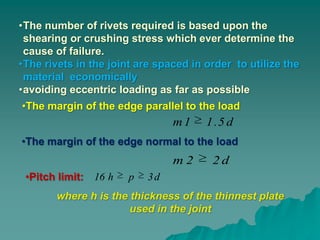
Riveted Joints
Riveting   applications
Rivets

Types  of riveted joints
Failure of riveted joints
Riveting applications:

  Pressure   vessels, boilers
  tanks
  Bridges
  Hulls of ships
  Airplanes
  Cranes
  buildings
  Machinery in general
Rivets
                                                  head
A rivet is a round bar consisting of
head
shank.
The rivet blank is heated to a red glow
Inserted into the holes;                          Shank
The head is held firmly against the       Point
   plate
The projecting end is formed into a
   second head, called the point,
Rivet material:

•Tough and ductile low carbon steel
•Nickel steel.
•Brass
•Aluminium
Types of riveted joints:

        Lap joints


                      Rivet
                              Strap

        butt joints
Riveted joint terminology.

                                 Gauge line


     Margin lap
                                      Pitch (p)
    distance ( m)


                    Back pitch (pt)
Failure of riveted joints
  Bending   of rivet or plate
    F                                 F


•In Lap connections the offset creates a moment
•     M=Ft/2
•Bending moment causes complex deformations
 and stresses
•In most cases this offset moment is neglected
•A suitable factor of safety is used.
b) Shearing of the rivets:
  Single shear
                                 FF

   F


  Double shear
       F/2
                             F
       F/2
Joint strength in shear
                                 2
                               πd S s
            Fs   (2 n 2   n1 )
                                 4
Where,
 n1: :number of rivets in single shear

 n2: number of rivets in double shear

 Ss: allowable shear stress

 d : diameter of rivet
c) Crushing of the rivets or the plates
 Crushing of margin
                  F                                          F


 Crushing of the rivet or plate occurs due to the pressure
 on the cylindrical surface of the rivet and the plate
 The resistance to crushing of rivets is,

                  Fc     (n 2 h 1      n 1 h 2 ) dS c
  where
  h1 h2: plate thickness
  Sc: allowable crushing stress
d) Rupture of plate by tension:

             F      L                   F


 Rupture of plate occurs at the section between the
  rivets
 The resistance of rupture can be obtained from the
  expression:
Where:                 Ft ( L nd ) hS t
 L: plate width

 h: plate thickness:

 St : allowable tensile stress

 n : number of rivet holes at the section
Undrilled
                       Section


             F                        F
                   L


   In the undrilled section:
                          Ft       LhS t
 Where
 L : width of plate
d) Tearing and shearing of the margin
  Tearing of the margin
                          F                   F


                               Margin
  Shearing of the margin
                           F                  F

For the riveted joint to resist tearing and
 shearing of the margin, the margin (m) =
1.5 d for double shear
2d for single shear.
Example:
Fig.(3) shows a lap riveted joint, consists of two Rolled steel plates,
SAE 1020, of 0.5 in thickness. The plates are riveted together with
four rivets 0.375 inch in diameter of low carbon steel, SAE 1010.
Estimate the maximum value of the force F that the joint can stand
while considering a factor of safety equals 2 and the rivets are driven
by hand hammer.                            0.5 in
                                                         F
              F


         4 in. 2
               1
                                    1
Solution
Shearing of the rivets:
d = 0.375
fs = 2
                                       π
                                                   2
n1 = 4    F            (2   n2   n1)
                                               d            Ss
                  s

n2 =0                                      4           fs
                            π 0 .375 Rivet-driving
                                         2
Load carrying member    Type of stress      10000                 Rivets acting in    Rivets acting in
                     Fs 4                  power                   single shear        double shear
Rolled steel, SAE 1020     Tension     4 2 …..                   18000               18000
                            Shear          Power                 13500               13500
Rivets, SAE1010
                       FS = Shear lb
                            2209           Hand                  10000               10000
                          Crushing         Power                 24000               30000
                          Crushing         Hand                  16000               20000
Crushing of the rivets:


                              (n 2 h1    n 1 h 2 ) dS c
                    Fc
                                         fs

Load carrying member       Type of stress
                             4 0 . 375 Rivet-driving Rivets acting in
                                          0 . 5 16000 shear              Rivets acting in
                     Fc                   power        single             double shear
Rolled steel, SAE 1020       Tension
                              Shear
                                          2 …..
                                          Power
                                                     18000
                                                     13500
                                                                        18000
                                                                        13500
                              Shear        Hand      10000              10000
Rivets, SAE1010
                             Crushing     Power      24000              30000
                         F = 6000 lb
                          C Crushing       Hand      16000              20000
Rupture of plate by tension

                                     (L        nd ) hS t
                         Ft
                                               fs
Load carrying member          Type of stress   Rivet-driving      Rivets acting in    Rivets acting in
                                  (4       2   0 . 375 ) 0 . 5
                                                   power
                                                                   18000
                                                                   single shear        double shear
Rolled steel, SAE 1020
                         Ft     Tension             …..          18000               18000
                                 Shear                2
                                                   Power         13500               13500
                                 Shear             Hand          10000               10000
Rivets, SAE1010
                         Ft = 14625 lb
                                Crushing
                                Crushing
                                                   Power
                                                   Hand
                                                                 24000
                                                                 16000
                                                                                     30000
                                                                                     20000
Crushing of the plates


                                  (n 2 h1              n 1 h 2 ) dS c
                     Fc
                                                       fs
 Load carrying member     Type of stress        Rivet-driving    Rivets acting in    Rivets acting in
                                 4       0 .5      0 . 375
                                                   power         36000
                                                                  single shear        double shear
Rolled steel, SAE 1020   Fc   Tension                …..        18000               18000
                               Shear                   2
                                                   Power        13500               13500
                               Shear               Hand         10000               10000
Rivets, SAE1010
                     FC = 13500 lb
                              Crushing
                              Crushing
                                                   Power
                                                   Hand
                                                                24000
                                                                16000
                                                                                    30000
                                                                                    20000


Maximum value of F = 2209 lb
Design procedure for structural joints

The following sequence of steps applies to the calculations
for structural joints:
• The load on each member is determined analytically or
  graphically
• The shape and size of each member is determined based
  on the load
• The diameter of the rivets is determined by the thickness
  of the structural shapes apply the equation:

                                            1
                             d      2h     16
•The number of rivets required is based upon the
 shearing or crushing stress which ever determine the
 cause of failure.
•The rivets in the joint are spaced in order to utilize the
 material economically
•avoiding eccentric loading as far as possible
•The margin of the edge parallel to the load
                                m1     1 .5 d
•The margin of the edge normal to the load
                                m2      2d
 •Pitch limit: 16 h    p   3d
       where h is the thickness of the thinnest plate
                      used in the joint
Thank You

Revited joints

  • 1.
  • 2.
    Riveting applications Rivets Types of riveted joints Failure of riveted joints
  • 3.
    Riveting applications: Pressure vessels, boilers  tanks  Bridges  Hulls of ships  Airplanes  Cranes  buildings  Machinery in general
  • 4.
    Rivets head A rivet is a round bar consisting of head shank. The rivet blank is heated to a red glow Inserted into the holes; Shank The head is held firmly against the Point plate The projecting end is formed into a second head, called the point,
  • 5.
    Rivet material: •Tough andductile low carbon steel •Nickel steel. •Brass •Aluminium
  • 6.
    Types of rivetedjoints: Lap joints Rivet Strap butt joints
  • 7.
    Riveted joint terminology. Gauge line Margin lap Pitch (p) distance ( m) Back pitch (pt)
  • 8.
    Failure of rivetedjoints  Bending of rivet or plate F F •In Lap connections the offset creates a moment • M=Ft/2 •Bending moment causes complex deformations and stresses •In most cases this offset moment is neglected •A suitable factor of safety is used.
  • 9.
    b) Shearing ofthe rivets: Single shear FF F Double shear F/2 F F/2
  • 10.
    Joint strength inshear 2 πd S s Fs (2 n 2 n1 ) 4 Where,  n1: :number of rivets in single shear  n2: number of rivets in double shear  Ss: allowable shear stress  d : diameter of rivet
  • 11.
    c) Crushing ofthe rivets or the plates Crushing of margin F F Crushing of the rivet or plate occurs due to the pressure on the cylindrical surface of the rivet and the plate The resistance to crushing of rivets is, Fc (n 2 h 1 n 1 h 2 ) dS c where h1 h2: plate thickness Sc: allowable crushing stress
  • 12.
    d) Rupture ofplate by tension: F L F  Rupture of plate occurs at the section between the rivets  The resistance of rupture can be obtained from the expression: Where: Ft ( L nd ) hS t  L: plate width  h: plate thickness:  St : allowable tensile stress  n : number of rivet holes at the section
  • 13.
    Undrilled Section F F L  In the undrilled section: Ft LhS t  Where  L : width of plate
  • 14.
    d) Tearing andshearing of the margin Tearing of the margin F F Margin Shearing of the margin F F For the riveted joint to resist tearing and shearing of the margin, the margin (m) = 1.5 d for double shear 2d for single shear.
  • 15.
    Example: Fig.(3) shows alap riveted joint, consists of two Rolled steel plates, SAE 1020, of 0.5 in thickness. The plates are riveted together with four rivets 0.375 inch in diameter of low carbon steel, SAE 1010. Estimate the maximum value of the force F that the joint can stand while considering a factor of safety equals 2 and the rivets are driven by hand hammer. 0.5 in F F 4 in. 2 1 1
  • 16.
    Solution Shearing of therivets: d = 0.375 fs = 2 π 2 n1 = 4 F (2 n2 n1) d Ss s n2 =0 4 fs π 0 .375 Rivet-driving 2 Load carrying member Type of stress 10000 Rivets acting in Rivets acting in Fs 4 power single shear double shear Rolled steel, SAE 1020 Tension 4 2 ….. 18000 18000 Shear Power 13500 13500 Rivets, SAE1010 FS = Shear lb 2209 Hand 10000 10000 Crushing Power 24000 30000 Crushing Hand 16000 20000
  • 17.
    Crushing of therivets: (n 2 h1 n 1 h 2 ) dS c Fc fs Load carrying member Type of stress 4 0 . 375 Rivet-driving Rivets acting in 0 . 5 16000 shear Rivets acting in Fc power single double shear Rolled steel, SAE 1020 Tension Shear 2 ….. Power 18000 13500 18000 13500 Shear Hand 10000 10000 Rivets, SAE1010 Crushing Power 24000 30000 F = 6000 lb C Crushing Hand 16000 20000
  • 18.
    Rupture of plateby tension (L nd ) hS t Ft fs Load carrying member Type of stress Rivet-driving Rivets acting in Rivets acting in (4 2 0 . 375 ) 0 . 5 power 18000 single shear double shear Rolled steel, SAE 1020 Ft Tension ….. 18000 18000 Shear 2 Power 13500 13500 Shear Hand 10000 10000 Rivets, SAE1010 Ft = 14625 lb Crushing Crushing Power Hand 24000 16000 30000 20000
  • 19.
    Crushing of theplates (n 2 h1 n 1 h 2 ) dS c Fc fs Load carrying member Type of stress Rivet-driving Rivets acting in Rivets acting in 4 0 .5 0 . 375 power 36000 single shear double shear Rolled steel, SAE 1020 Fc Tension ….. 18000 18000 Shear 2 Power 13500 13500 Shear Hand 10000 10000 Rivets, SAE1010 FC = 13500 lb Crushing Crushing Power Hand 24000 16000 30000 20000 Maximum value of F = 2209 lb
  • 20.
    Design procedure forstructural joints The following sequence of steps applies to the calculations for structural joints: • The load on each member is determined analytically or graphically • The shape and size of each member is determined based on the load • The diameter of the rivets is determined by the thickness of the structural shapes apply the equation: 1 d 2h 16
  • 21.
    •The number ofrivets required is based upon the shearing or crushing stress which ever determine the cause of failure. •The rivets in the joint are spaced in order to utilize the material economically •avoiding eccentric loading as far as possible •The margin of the edge parallel to the load m1 1 .5 d •The margin of the edge normal to the load m2 2d •Pitch limit: 16 h p 3d where h is the thickness of the thinnest plate used in the joint
  • 22.