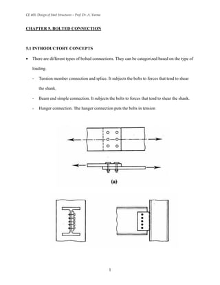
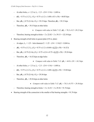
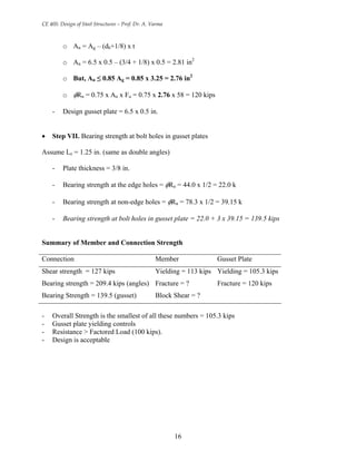
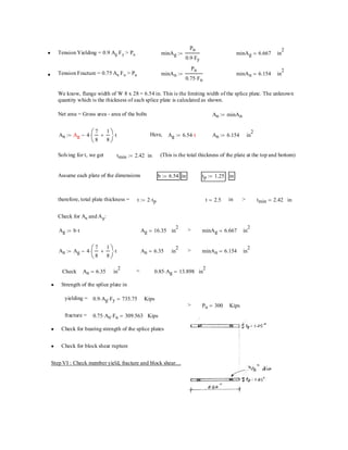
SlideShare a Scribd company logo
CE 405: Design of Steel Structures – Prof. Dr. A. Varma
CHAPTER 5. BOLTED CONNECTION
5.1 INTRODUCTORY CONCEPTS
• There are different types of bolted connections. They can be categorized based on the type of
loading.
- Tension member connection and splice. It subjects the bolts to forces that tend to shear
the shank.
- Beam end simple connection. It subjects the bolts to forces that tend to shear the shank.
- Hanger connection. The hanger connection puts the bolts in tension
1
CE 405: Design of Steel Structures – Prof. Dr. A. Varma
• The bolts are subjected to shear or tension loading.
- In most bolted connection, the bolts are subjected to shear.
- Bolts can fail in shear or in tension.
- You can calculate the shear strength or the tensile strength of a bolt
• Simple connection: If the line of action of the force acting on the connection passes through
the center of gravity of the connection, then each bolt can be assumed to resist an equal share
of the load.
• The strength of the simple connection will be equal to the sum of the strengths of the
individual bolts in the connection.
• We will first concentrate on bolted shear connections.
2
CE 405: Design of Steel Structures – Prof. Dr. A. Varma
5.2 BOLTED SHEAR CONNECTIONS
• We want to design the bolted shear connections so that the factored design strength (φ Rn) is
greater than or equal to the factored load.
• So, we need to examine the various possible failure modes and calculate the corresponding
design strengths.
• Possible failure modes are:
- Shear failure of the bolts
- Failure of member being connected due to fracture or block shear or ….
- Edge tearing or fracture of the connected plate
- Tearing or fracture of the connected plate between two bolt holes
- Excessive bearing deformation at the bolt hole
• Shear failure of bolts
- Average shearing stress in the bolt = fv = P/A = P/(π db
2
/4)
- P is the load acting on an individual bolt
- A is the area of the bolt and db is its diameter
- Strength of the bolt = P = fv x (π db
2
/4) where fv = shear yield stress = 0.6Fy
- Bolts can be in single shear or double shear as shown below.
- When the bolt is in double shear, two cross-sections are effective in resisting the load.
The bolt in double shear will have the twice the shear strength of a bolt in single shear.
3
CE 405: Design of Steel Structures – Prof. Dr. A. Varma
• Failure of connected member
- We have covered this in detail in Ch. 2 on tension members
- Member can fail due to tension fracture or block shear.
• Bearing failure of connected/connecting part due to bearing from bolt holes
- Hole is slightly larger than the fastener and the fastener is loosely placed in hole
- Contact between the fastener and the connected part over approximately half the
circumference of the fastener
- As such the stress will be highest at the radial contact point (A). However, the average
stress can be calculated as the applied force divided by the projected area of contact
- Average bearing stress fp = P/(db t), where P is the force applied to the fastener.
- The bearing stress state can be complicated by the presence of nearby bolt or edge. The
bolt spacing and edge distance will have an effect on the bearing str.
- Bearing stress effects are independent of the bolt type because the bearing stress acts on
the connected plate not the bolt.
4
CE 405: Design of Steel Structures – Prof. Dr. A. Varma
- A possible failure mode resulting from excessive bearing close to the edge of the
connected element is shear tear-out as shown below. This type of shear tear-out can also
occur between two holes in the direction of the bearing load.
Rn = 2 x 0.6 Fu Lc t = 1.2 Fu Lc t
5
CE 405: Design of Steel Structures – Prof. Dr. A. Varma
- To prevent excessive deformation of the hole, an upper limit is placed on the bearing
load. This upper limit is proportional to the fracture stress times the projected bearing
area
Rn = C x Fu x bearing area = C Fu db t
If deformation is not a concern then C = 3, If deformation is a concern then C=2.4
C = 2.4 corresponds to a deformation of 0.25 in.
- Finally, the equation for the bearing strength of a single bolts is φRn
where, φ = 0.75 and Rn = 1.2 Lc t Fu < 2.4 db t Fu
Lc is the clear distance in the load direction, from the edge of the bolt hole to the edge of
the adjacent hole or to the edge of the material
- This relationship can be simplified as follows:
The upper limit will become effective when 1.2 Lc t Fu = 2.4 db t Fu
i.e., the upper limit will become effective when Lc = 2 db
If Lc < 2 db, Rn = 1.2 Lc t Fu
If Lc > 2 db, Rn = 1.4 db t Fu
6
CE 405: Design of Steel Structures – Prof. Dr. A. Varma
5.3 DESIGN PROVISIONS FOR BOLTED SHEAR CONNECTIONS
• In a simple connection, all bolts share the load equally.
T
T
T/n T/n
T/n T/n
T/n T/n
T
T
T/n T/n
T/n T/n
T/n T/n
• In a bolted shear connection, the bolts are subjected to shear and the connecting / connected
plates are subjected to bearing stresses.
Bolt in shear
Bearing stresses in plate
T
T
T
T
Bolt in shear
Bearing stresses in plate
Bolt in shear
Bearing stresses in plate
T
T
T
T
• The shear strength of all bolts = shear strength of one bolt x number of bolts
• The bearing strength of the connecting / connected plates can be calculated using equations
given by AISC specifications.
• The tension strength of the connecting / connected plates can be calculated as discussed
earlier in Chapter 2.
5.3.1 AISC Design Provisions
• Chapter J of the AISC Specifications focuses on connections.
• Section J3 focuses on bolts and threaded parts
7
CE 405: Design of Steel Structures – Prof. Dr. A. Varma
• AISC Specification J3.3 indicates that the minimum distance (s) between the centers of bolt
holes is 2 bd
3
2
. A distance of 3db is preferred.
• AISC Specification J3.4 indicates that the minimum edge distance (Le) from the center of the
bolt to the edge of the connected part is given in Table J3.4 on page 16.1-61. Table J3.4
specifies minimum edge distances for sheared edges, edges of rolled shapes, and gas cut
edges.
• AISC Specification J3.5 indicates that the maximum edge distance for bolt holes is 12 times
the thickness of the connected part (but not more than 6 in.). The maximum spacing for bolt
holes is 24 times the thickness of the thinner part (but not more than 12 in.).
• Specification J3.6 indicates that the design tension or shear strength of bolts is φ FnAb
- Table J3.2 gives the values of φ and Fn
- Ab is the unthreaded area of bolt.
- In Table J3.2, there are different types of bolts A325 and A490.
- The shear strength of the bolts depends on whether threads are included or excluded from
the shear planes. If threads are included in the shear planes then the strength is lower.
- We will always assume that threads are included in the shear plane, therefore less
strength to be conservative.
• We will look at specifications J3.7 – J3.9 later.
• AISC Specification J3.10 indicates the bearing strength of plates at bolt holes.
- The design bearing strength at bolt holes is φRn
- Rn = 1.2 Lc t Fu ≤ 2.4 db t Fu - deformation at the bolt holes is a
design consideration
- Where, Fu = specified tensile strength of the connected material
8
CE 405: Design of Steel Structures – Prof. Dr. A. Varma
- Lc = clear distance, in the direction of the force, between the edge of the hole and the
edge of the adjacent hole or edge of the material (in.).
- t = thickness of connected material
5.3.2 AISC Design Tables
• Table 7-10 on page 7-33 of the AISC Manual gives the design shear of one bolt. Different
bolt types (A325, A490), thread condition (included or excluded), loading type (single shear
or double shear), and bolt diameters (5/8 in. to 1-1/2 in.) are included in the Table.
• Table 7-11 on page 7-33 of the AISC Manual is an extension of Table 7-10 with the
exception that it gives the shear strength of ‘n’ bolts.
• Table 7-12 on page 7-34 of the AISC manual gives the design bearing strength at bolt holes
for various bolt spacings.
- These design bearing strengths are in kips/in. thickness.
- The tabulated numbers must be multiplied by the plate thickness to calculate the design
bearing strength of the plate.
- The design bearing strengths are given for different bolt spacings (2.67db and 3db),
different Fu (58 and 65 ksi), and different bolt diameters (5/8 – 1-1/2 in.)
- Table 7-12 also includes the spacing (sfull) required to develop the full bearing strength
for different Fu and bolt diameters
- Table 7-12 also includes the bearing strength when s > sfull
- Table 7-12 also includes the minimum spacing 2-2/3 db values
• Table 7-13 in the AISC manual on page 7-35 is similar to Table 7-12. It gives the design
bearing strength at bolt holes for various edge distances.
9
CE 405: Design of Steel Structures – Prof. Dr. A. Varma
- These design bearing strengths are in kips/in. thickness.
- The tabulated numbers must be multiplied by the plate thickness to calculate the design
bearing strength of the plate.
- The design bearing strengths are given for different edge distances (1.25 in. and 2 in.),
different Fu (58 and 65 ksi), and different bolt diameters (5/8 – 1-1/2 in.)
- Table 7-13 also includes the edge distance (Le full) required to develop the full bearing
strength for different Fu and bolt diameters
- Table 7-13 also includes the bearing strength when Le > Le full
10
CE 405: Design of Steel Structures – Prof. Dr. A. Varma
Example 5.1 Calculate and check the design
strength of the connection shown below. Is
the connection adequate for carrying the
factored load of 65 kips.
1.25 2.50 1.25
1.25
2.50
1.25
65 k
A36
A36 5 x ½
3/8 in.
¾ in. bolts
1.25 2.50 1.25
1.25
2.50
1.25
65 k
A36
A36 5 x ½
3/8 in.
¾ in. bolts
Solution
Step I. Shear strength of bolts
• The design shear strength of one bolt in shear = φ Fn Ab = 0.75 x 48 x π x 0.752
/4
- φ Fn Ab = 15.9 kips per bolt (See Table J3.2 and Table 7-10)
- Shear strength of connection = 4 x 15.9 = 63.6 kips (See Table 7-11)
Step II. Minimum edge distance and spacing requirements
• See Table J3.4, minimum edge distance = 1 in. for rolled edges of plates
- The given edge distances (1.25 in.) > 1 in. Therefore, minimum edge distance
requirements are satisfied.
• Minimum spacing = 2.67 db = 2.67 x 0.75 = 2.0 in.
- Preferred spacing = 3.0 db = 3.0 x 0.75 = 2.25 in.
- The given spacing (2.5 in.) > 2.25 in. Therefore, spacing requirements are satisfied.
Step III. Bearing strength at bolt holes.
• Bearing strength at bolt holes in connected part (5 x ½ in. plate)
- At edges, Lc = 1.25 – hole diameter/2 = 1.25 – (3/4 + 1/16)/2 = 0.844 in.
- φRn = 0.75 x (1.2 Lc t Fu) = 0.75 x (1.2 x 0.844 x 0.5 x 58) = 22.02 kips
- But, φRn ≤ 0.75 (2.4 db t Fu) = 0.75 x (2.4 x 0.75 x 0.5 x 58) = 39.15 kips
- Therefore, φRn = 22.02 kips at edge holes
• Compare with value in Table 7-13. φRn = 44.0 x 0.5 = 22.0 kips
11
CE 405: Design of Steel Structures – Prof. Dr. A. Varma
- At other holes, s = 2.5 in, Lc = 2.5 – (3/4 +1/16) = 1.688 in.
- φRn = 0.75 x (1.2 Lc t Fu) = 0.75 x (1.2 x 1.688 x 0.5 x 58) = 44.05 kips
- But, φRn ≤ 0.75 (2.4 db t Fu) = 39.15 kips. Therefore φRn = 39.15 kips
- Therefore, φRn = 39.15 kips at other holes
• Compare with value in Table 7-12. φRn = 78.3 x 0.5 =39.15 kips
- Therefore, bearing strength at holes = 2 x 22.02 + 2 x 39.15 = 122.34 kips
• Bearing strength at bolt holes in gusset plate (3/8 in. plate)
- At edges, Lc = 1.25 – hole diameter/2 = 1.25 – (3/4 + 1/16)/2 = 0.844 in.
- φRn = 0.75 x (1.2 Lc t Fu) = 0.75 x (1.2 x 0.844 x 0.375 x 58) = 16.52 k
- But, φRn ≤ 0.75 (2.4 db t Fu) = 0.75 x (2.4 x 0.75 x 0.375 x 58) = 29.36 kips
- Therefore, φRn = 16.52 kips at edge holes
• Compare with value in Table 7-13. φRn = 44.0 x 3/8 = 16.5 kips
- At other holes, s = 2.5 in, Lc = 2.5 – (3/4 +1/16) = 1.688 in.
- φRn = 0.75 x (1.2 Lc t Fu) = 0.75 x (1.2 x 1.688 x 0.375 x 58) = 33.04 kips
- But, φRn ≤ 0.75 (2.4 db t Fu) = 29.36 kips
- Therefore, φRn = 29.36 kips at other holes
• Compare with value in Table 7-12. φRn = 78.3 x 0.375 = 29.36 kips
- Therefore, bearing strength at holes = 2 x 16.52 + 2 x 29.36 = 91.76 kips
• Bearing strength of the connection is the smaller of the bearing strengths = 91.76 kips
12
CE 405: Design of Steel Structures – Prof. Dr. A. Varma
Connection Strength
Shear strength = 63.3 kips
Bearing strength (plate) = 122.34 kips
Bearing strength (gusset) = 91.76 kips
Connection strength (φRn) > applied factored loads (γQ). Therefore ok.
13
CE 405: Design of Steel Structures – Prof. Dr. A. Varma
Example 5.2 Design a double angle tension member and a gusset plated bolted connection
system to carry a factored load of 100 kips. Assume A36 (36 ksi yield stress) material for the
double angles and the gusset plate. Assume A325 bolts. Note that you have to design the double
angle member sizes, the gusset plate thickness, the bolt diameter, numbers, and spacing.
Solution
Step I. Design and select a trial tension member
• See Table 3-7 on page 3-33 of the AISC manual.
- Select 2L 3 x 2 x 3/8 with φPn = 113 kips (yielding) and 114 kips (fracture)
- While selecting a trial tension member check the fracture strength with the load.
Step II. Select size and number of bolts
The bolts are in double shear for this design (may not be so for other designs)
• See Table 7-11 on page 7-33 in the AISC manual
Use four 3/4 in. A325 bolts in double shear
φRn = 127 kips - shear strength of bolts from Table 7-11
Step III. Design edge distance and bolt spacing
• See Table J3.4
- The minimum edge distance = 1 in. for 3/4 in. diameter bolts in rolled edges.
- Select edge distance = 1.25 in.
• See specification J3.5
- Minimum spacing = 2.67 db = 2.0 in.
- Preferred spacing = 3.0 db = 2.25 in.
- Select spacing = 3.0 in., which is greater than preferred or minimum spacing
14
CE 405: Design of Steel Structures – Prof. Dr. A. Varma
Step IV. Check the bearing strength at bolt holes in angles
• Bearing strength at bolt holes in angles
- Angle thickness = 3/8 in.
- See Table 7-13 for the bearing strength per in. thickness at the edge holes
- Bearing strength at the edge holes (Le = 1.25 in.) = φRn = 44.0 x 3/8 = 16.5 k
- See Table 7-12 for the bearing strength per in. thickness at non-edge holes
- Bearing strength at non-edge holes (s = 3 in.) = φRn = 78.3 x 3/8 = 29.4 k
- Bearing strength at bolt holes in each angle = 16.5 + 3 x 29.4 = 104.7 kips
- Bearing strength of double angles = 2 x 104.7 kips = 209.4 kips
Step V. Check the fracture and block shear strength of the tension member
• This has been covered in the chapter on tension members and is left to the students.
Step VI. Design the gusset plate
• See specification J5.2 for designing gusset plates. These plates must be designed for the
limit states of yielding and rupture
- Limit state of yielding
o φRn = 0.9 Ag Fy > 100 kips
o Therefore, Ag = L x t > 3.09 in2
o Assume t = ½ in; Therefore L > 6.18 in.
o Design gusset plate = 6.5 x ½ in.
o Yield strength = φRn = 0.9 x 6.5 x 0.5 x 36 = 105.3 kips
- Limit state for fracture
15
CE 405: Design of Steel Structures – Prof. Dr. A. Varma
o An = Ag – (db+1/8) x t
o An = 6.5 x 0.5 – (3/4 + 1/8) x 0.5 = 2.81 in2
o But, An ≤ 0.85 Ag = 0.85 x 3.25 = 2.76 in2
o φRn = 0.75 x An x Fu = 0.75 x 2.76 x 58 = 120 kips
- Design gusset plate = 6.5 x 0.5 in.
• Step VII. Bearing strength at bolt holes in gusset plates
Assume Le = 1.25 in. (same as double angles)
- Plate thickness = 3/8 in.
- Bearing strength at the edge holes = φRn = 44.0 x 1/2 = 22.0 k
- Bearing strength at non-edge holes = φRn = 78.3 x 1/2 = 39.15 k
- Bearing strength at bolt holes in gusset plate = 22.0 + 3 x 39.15 = 139.5 kips
Summary of Member and Connection Strength
Connection Member Gusset Plate
Shear strength = 127 kips Yielding = 113 kips Yielding = 105.3 kips
Bearing strength = 209.4 kips (angles) Fracture = ? Fracture = 120 kips
Bearing Strength = 139.5 (gusset) Block Shear = ?
- Overall Strength is the smallest of all these numbers = 105.3 kips
- Gusset plate yielding controls
- Resistance > Factored Load (100 kips).
- Design is acceptable
16
CE 405: Design of Steel Structures – Prof. Dr. A. Varma
5.4 SLIP-CRITICAL BOLTED CONNECTIONS
• High strength (A325 and A490) bolts can be installed with such a degree of tightness that
they are subject to large tensile forces.
• These large tensile forces in the bolt clamp the connected plates together. The shear force
applied to such a tightened connection will be resisted by friction as shown in the Figure
below.
Tightened
P
P
TightenedTightened
P
P
P
P
Tb
N =Tb
N =Tb
N =Tb
P
F=µN
Tb
N = Tb
F=µN
N = Tb
N =Tb
P
Tb
N =Tb
Tb
N =Tb
N =Tb
N =Tb
P
F=µN
N =Tb
N =Tb
P
F=µN
Tb
N = Tb
Tb
N = Tb
F=µN
N = Tb
N =Tb
P
F=µN
N = Tb
N =Tb
N = Tb
N =Tb
P
• Thus, slip-critical bolted connections can be designed to resist the applied shear forces using
friction. If the applied shear force is less than the friction that develops between the two
surfaces, then no slip will occur between them.
• However, slip will occur when the friction force is less than the applied shear force. After
slip occurs, the connection will behave similar to the bearing-type bolted connections
designed earlier.
17
CE 405: Design of Steel Structures – Prof. Dr. A. Varma
• Table J3.1 summarizes the minimum bolt tension that must be applied to develop a slip-
critical connection.
• The shear resistance of fully tensioned bolts to slip at factored loads is given by AISC
Specification J3.8 a
Shear resistance at factored load = φRn = 1.13 µ Tb Ns
where, φ = 1.0 for standard holes
µ = 0.33 (Class A surface with unpainted clean mill scale surface: CE 405)
Tb = minimum bolt tension given in Table J3.1
Ns = number of slip planes
- See Table 7-15 on page 7-36 of the AISC manual. This Table gives the shear resistance
of fully tensioned bolts to slip at factored loads on class A surfaces.
- For example, the shear resistance of 1-1/8 in. bolt fully tensioned to 56 kips (Table J3.1)
is equal to 20.9 kips (Class A faying surface).
- When the applied shear force exceeds the φRn value stated above, slip will occur in the
connection.
• The shear resistance of fully tensioned bolts to slip at service loads is given by AISC
Specification J3.8 b.
- Shear resistance at service load = φRn = φ Fv Ab
- Where, φ = 1.0 for standard holes
Fv = slip-critical resistance to shear at service loads, see Table A-J3.2 on
page 16.1-116 of the AISC manual
- See Table 7-16 on page 7-37 of the AISC manual. This Table gives the shear resistance
of fully tensioned bolts to slip at service loads on class A surfaces.
18
CE 405: Design of Steel Structures – Prof. Dr. A. Varma
- For example, the shear resistance of 1-1/8 in. bolt fully tensioned to 56 kips (Table J3.1)
is equal to 16.9 kips (Class A faying surface).
- When the applied shear force exceeds the φRn value stated above, slip will occur in the
connection.
• The final strength of the connection will depend on the shear strength of the bolts calculated
using the values in Table 7-11 and on the bearing strength of the bolts calculated using the
values in Table 7-12, 7-13. This is the same strength as that of a bearing type connection.
19
CE 405: Design of Steel Structures – Prof. Dr. A. Varma
Example 5.3 Design a slip-critical splice for a tension member subjected to 300 kips of tension
loading. The tension member is a W8 x 28 section made from A992 (50 ksi) material. The
unfactored dead load is equal to 50 kips and the unfactored live load is equal to 150 kips. Use
A325 bolts. The splice should be slip-critical at service loads.
Solution
Step I. Service and factored loads
• Service Load = D + L = 200 kips.
• Factored design load = 1.2 D + 1.6 L = 300 kips
• Tension member is W8 x 28 section made from A992 (50 ksi) steel. The tension splice must
be slip critical (i.e., it must not slip) at service loads.
Step II. Slip-critical splice connection
• φRn of one fully-tensioned slip-critical bolt = φ Fv Ab (See Spec. A-J3.8 b)
page 16.1-117 of AISC
• If db = 3/4 in.
φRn of one bolt = 1.0 x 17 x π x 0.752
/4 = 7.51 kips
Note, Fv = 17 ksi from Table A-J3.2
From Table 7-16 on page 7-37 φRn = 7.51 kips
φRn of n bolts = 7.51 x n > 200 kips (splice must be slip-critical at service)
Therefore, n > 26.63
• If db = 7/8 in.
φRn of one bolt = 10.2 kips -from Table 7-16
φRn of n bolts = 10.2 x n > 200 kips (splice must be slip-critical at service)
Therefore, n > 19.6 bolts
20
Number of bolts required n
Ps
φRn
:= n 26.63= (min. reqd.)
If diameter of the bolt =• db
7
8
:= in Ab
π
4
db( )2
:=
for one bolt φRn φ Fv⋅ Ab⋅:= φRn 10.222= Kips
Number of bolts required n
Ps
φRn
:= n 19.565= (min. reqd.)
say we provide 24 bolts on either side of the center line, 6 on either side of the flanges, top + bottom
Step III: Connection Details and spacings for 24 bolts on each W8 x 28
Note that there are 24 bolts on either side of the center line. In all there are 48 number - 7/8 in dia bolts•
used in the connection.
Minimum pretension applied to the bolts = 39.0 Kips from Table J3.1•
Minimum Edge distance from Table J3.4 = Le-min = 1.125 in•
Provide Edge Distance =• Le 1.25:= in
Minimum spacing (Spec. J3.3) =• s 2.67 db⋅:= s 2.336= in
Example 5.3
Step I: Service and Factored Loads
D 50:= Kips L 150:= Kips
Service Loads• Ps D L+:= Ps 200= Kips
Factored Loads• Pu 1.2 D⋅ 1.6 L⋅+:= Pu 300= Kips
Step II: Slip Critical connection
In Service loads consideration, φRn of one fully tenstioned slip-critical bolt = φ Fv Ab•
(As given in Spec. A-J3.8b - page 16.1-117) φ 1.0:= Fv 17:= Ksi - A325 - Table A-J3.2
If diameter of the bolt =• db
3
4
:= in Ab
π
4
db( )2
:=
for one bolt φRn φ Fv⋅ Ab⋅:= φRn 7.51= Kips
KipsPu 300=KsiFu 65:=KsiFy 50:=Step V: Design the splice plate
KipsBt 2.223 10
3
×=
Bt 4 Be⋅ 20 Bo⋅+:=Total bearing strength of the bolt holes in wide flange section•
Table 7-12Kip / in thicknessBo 102:=Bearing strength of 7/8 in. bolt at other holes =•
Table 7-13
Preferred spacing = s 3 db⋅:= s 2.625= in
From table 7-12 sfull 2.6875:= in
For design provide spacing = s 3:= in
Step IV: Connection Strength at factored loads
The splice connection should be designed as a normal shear / bearing connection beyong this point for the•
factored load = 300 kips
The shear strength of the bolts (Table 7-10) = 21.6 kips/bolt x 24 bolts = 518.4 Kips•
Bearing strength of 7/8 in. bolt at edge holes =• Be 45.7:= Kip / in thickness
Ag b t⋅:= Ag 16.35= in
2
> minAg 6.667= in
2
An Ag 4
7
8
1
8
+⎛
⎜
⎝
⎞
⎠
⋅ t⋅−:= An 6.35= in
2
> minAn 6.154= in
2
Check An 6.35= in
2
< 0.85 Ag⋅ 13.898= in
2
Strength of the splice plate in•
yielding = 0.9 Ag⋅ Fy⋅ 735.75= Kips
> Pu 300= Kips
fracture = 0.75 An⋅ Fu⋅ 309.563= Kips
Check for bearing strength of the splice plates•
Check for block shear rupture•
Step VI : Check member yield, fracture and block shear....
Tension Yielding = 0.9 Ag Fy > Pu• minAg
Pu
0.9 Fy⋅
:= minAg 6.667= in
2
Tension Fracture = 0.75 An Fu > Pu• minAn
Pu
0.75 Fu⋅
:= minAn 6.154= in
2
We know, flange width of W 8 x 28 = 6.54 in. This is the limiting width of the splice plate. The unknown
quantity which is the thickness of each splice plate is calculated as shown.
Net area = Gross area - area of the bolts An minAn:=
An Ag 4
7
8
1
8
+⎛
⎜
⎝
⎞
⎠
⋅ t⋅−:= Ag Here, Ag 6.54 t⋅:= t An 6.154:= in
2
Check for An and Ag:
intmin 2.42=>int 2.5=t 2 tp⋅:=therefore, total plate thickness =
intp 1.25:=inb 6.54:=Assume each plate of the dimensions
(This is the total thickness of the plate at the top and bottom)intmin 2.42:=Solving for t, we get
CE 405: Design of Steel Structures – Prof. Dr. A. Varma
Example 4.4 Modify Example 4.2 so that the connection system is slip critical for the factored
load of 100 kips.
Solution
Step I. Design and select a trial tension member (same as example 4.2)
• Select 2L 3 x 2 x 3/8 with φPn = 113 kips (yielding) and 114 kips (fracture)
Step II. Select size and number of bolts (modified step)
• The connection must be designed to be slip-critical at the factored loads
- φRn for one bolt = 1.0 x 1.13 x µ x Tb x Ns (Tb from Table J3.1)
- φRn for one 3/4 in. bolt = 1.0 x 1.13 x 0.33 x 28 x 2 = 20.9 kips
- φRn for one 7/8 in. bolt = 1.0 x 1.13 x 0.33 x 39 x 2 = 29.1 kips
- See Values in Table 7-15.
φRn for ¾ and 7/8 in. bolts in double slip = 20.9 and 29.1 kips, respectively.
- We need at least five ¾ in. bolts to have strength φRn = 5 x 20.9 = 104.5 k > 100 k
- We need at least four 7/8 in. bolts to have strength φRn = 4 x 29.1 = 116.4 k> 100
• Use five ¾ in. fully tightened bolts. Bolts must be tightened to 28 kips.
• Compare with solution for example 4.2 where only four snug-tight ¾ in bolts design.
For the remaining steps III to VII follow Example 4.2
Step III. Design edge distance and bolt spacing
Step IV. Check the bearing strength at bolt holes in angles
Step V. Check the fracture and block shear strength of the tension member
Step VI. Design the gusset plate
Step VII. Bearing strength at bolt holes in gusset plates
Summary of Member and Connection Strength
23

More Related Content

What's hot

Ch6 Composite Plate Girder Bridges (Steel Bridges تصميم الكباري المعدنية & Pr...
Ch6 Composite Plate Girder Bridges (Steel Bridges تصميم الكباري المعدنية & Pr...Ch6 Composite Plate Girder Bridges (Steel Bridges تصميم الكباري المعدنية & Pr...
Ch6 Composite Plate Girder Bridges (Steel Bridges تصميم الكباري المعدنية & Pr...
Hossam Shafiq II
 
Steel Structural Design Manual for Engineers
Steel Structural Design Manual for EngineersSteel Structural Design Manual for Engineers
Steel Structural Design Manual for Engineers
Prem Chand Sharma
 
Unit 5.2 Welded joints
Unit 5.2 Welded jointsUnit 5.2 Welded joints
Unit 5.2 Welded joints
Yugal Kishor Sahu
 
Types of fasteners and fixings
Types of fasteners and fixingsTypes of fasteners and fixings
Types of fasteners and fixings
The WDS Group
 
Design of Beam for Shear
Design of Beam for ShearDesign of Beam for Shear
Design of Beam for Shearillpa
 
Punching Shears 1.1
Punching Shears 1.1Punching Shears 1.1
Punching Shears 1.1Milan Stanic
 
Lecture note on column design
Lecture note on column designLecture note on column design
Lecture note on column design
Niyogakiza Philemon
 
Lec13 Continuous Beams and One Way Slabs(3) Footings (Reinforced Concrete Des...
Lec13 Continuous Beams and One Way Slabs(3) Footings (Reinforced Concrete Des...Lec13 Continuous Beams and One Way Slabs(3) Footings (Reinforced Concrete Des...
Lec13 Continuous Beams and One Way Slabs(3) Footings (Reinforced Concrete Des...
Hossam Shafiq II
 
Ch5 Plate Girder Bridges (Steel Bridges تصميم الكباري المعدنية & Prof. Dr. Me...
Ch5 Plate Girder Bridges (Steel Bridges تصميم الكباري المعدنية & Prof. Dr. Me...Ch5 Plate Girder Bridges (Steel Bridges تصميم الكباري المعدنية & Prof. Dr. Me...
Ch5 Plate Girder Bridges (Steel Bridges تصميم الكباري المعدنية & Prof. Dr. Me...
Hossam Shafiq II
 
Guide for the design of crane supporting steel structures
Guide for the design of crane supporting steel structuresGuide for the design of crane supporting steel structures
Guide for the design of crane supporting steel structures
Timóteo Rocha
 
Rc detailing-to-ec2
Rc detailing-to-ec2Rc detailing-to-ec2
Rc detailing-to-ec2
Luan Truong Van
 
255788330 asi-steel-connections
255788330 asi-steel-connections255788330 asi-steel-connections
255788330 asi-steel-connections
Juan Jose Bazalar Carreño
 
CE72.52 - Lecture 3b - Section Behavior - Shear and Torsion
CE72.52 - Lecture 3b - Section Behavior - Shear and TorsionCE72.52 - Lecture 3b - Section Behavior - Shear and Torsion
CE72.52 - Lecture 3b - Section Behavior - Shear and Torsion
Fawad Najam
 
Eurocode 2 design of composite concrete
Eurocode 2 design of composite concreteEurocode 2 design of composite concrete
Eurocode 2 design of composite concrete
Jo Gijbels
 
22-Design of Four Bolt Extended Endplate Connection (Steel Structural Design ...
22-Design of Four Bolt Extended Endplate Connection (Steel Structural Design ...22-Design of Four Bolt Extended Endplate Connection (Steel Structural Design ...
22-Design of Four Bolt Extended Endplate Connection (Steel Structural Design ...
Hossam Shafiq II
 
Precast design (1)
Precast design (1)Precast design (1)
Precast design (1)
Surya Singh
 
07-Strength of Bolted Connections (Steel Structural Design & Prof. Shehab Mou...
07-Strength of Bolted Connections (Steel Structural Design & Prof. Shehab Mou...07-Strength of Bolted Connections (Steel Structural Design & Prof. Shehab Mou...
07-Strength of Bolted Connections (Steel Structural Design & Prof. Shehab Mou...
Hossam Shafiq II
 
Column base plates_prof_thomas_murray
Column base plates_prof_thomas_murrayColumn base plates_prof_thomas_murray
Column base plates_prof_thomas_murray
Alberto Rosado
 
Theory for Welded connection.pdf
Theory for Welded connection.pdfTheory for Welded connection.pdf
Theory for Welded connection.pdf
YatiTank
 
Practical design and_detailing_of_steel_column_base_...
Practical design and_detailing_of_steel_column_base_...Practical design and_detailing_of_steel_column_base_...
Practical design and_detailing_of_steel_column_base_...suchit03
 

What's hot (20)

Ch6 Composite Plate Girder Bridges (Steel Bridges تصميم الكباري المعدنية & Pr...
Ch6 Composite Plate Girder Bridges (Steel Bridges تصميم الكباري المعدنية & Pr...Ch6 Composite Plate Girder Bridges (Steel Bridges تصميم الكباري المعدنية & Pr...
Ch6 Composite Plate Girder Bridges (Steel Bridges تصميم الكباري المعدنية & Pr...
 
Steel Structural Design Manual for Engineers
Steel Structural Design Manual for EngineersSteel Structural Design Manual for Engineers
Steel Structural Design Manual for Engineers
 
Unit 5.2 Welded joints
Unit 5.2 Welded jointsUnit 5.2 Welded joints
Unit 5.2 Welded joints
 
Types of fasteners and fixings
Types of fasteners and fixingsTypes of fasteners and fixings
Types of fasteners and fixings
 
Design of Beam for Shear
Design of Beam for ShearDesign of Beam for Shear
Design of Beam for Shear
 
Punching Shears 1.1
Punching Shears 1.1Punching Shears 1.1
Punching Shears 1.1
 
Lecture note on column design
Lecture note on column designLecture note on column design
Lecture note on column design
 
Lec13 Continuous Beams and One Way Slabs(3) Footings (Reinforced Concrete Des...
Lec13 Continuous Beams and One Way Slabs(3) Footings (Reinforced Concrete Des...Lec13 Continuous Beams and One Way Slabs(3) Footings (Reinforced Concrete Des...
Lec13 Continuous Beams and One Way Slabs(3) Footings (Reinforced Concrete Des...
 
Ch5 Plate Girder Bridges (Steel Bridges تصميم الكباري المعدنية & Prof. Dr. Me...
Ch5 Plate Girder Bridges (Steel Bridges تصميم الكباري المعدنية & Prof. Dr. Me...Ch5 Plate Girder Bridges (Steel Bridges تصميم الكباري المعدنية & Prof. Dr. Me...
Ch5 Plate Girder Bridges (Steel Bridges تصميم الكباري المعدنية & Prof. Dr. Me...
 
Guide for the design of crane supporting steel structures
Guide for the design of crane supporting steel structuresGuide for the design of crane supporting steel structures
Guide for the design of crane supporting steel structures
 
Rc detailing-to-ec2
Rc detailing-to-ec2Rc detailing-to-ec2
Rc detailing-to-ec2
 
255788330 asi-steel-connections
255788330 asi-steel-connections255788330 asi-steel-connections
255788330 asi-steel-connections
 
CE72.52 - Lecture 3b - Section Behavior - Shear and Torsion
CE72.52 - Lecture 3b - Section Behavior - Shear and TorsionCE72.52 - Lecture 3b - Section Behavior - Shear and Torsion
CE72.52 - Lecture 3b - Section Behavior - Shear and Torsion
 
Eurocode 2 design of composite concrete
Eurocode 2 design of composite concreteEurocode 2 design of composite concrete
Eurocode 2 design of composite concrete
 
22-Design of Four Bolt Extended Endplate Connection (Steel Structural Design ...
22-Design of Four Bolt Extended Endplate Connection (Steel Structural Design ...22-Design of Four Bolt Extended Endplate Connection (Steel Structural Design ...
22-Design of Four Bolt Extended Endplate Connection (Steel Structural Design ...
 
Precast design (1)
Precast design (1)Precast design (1)
Precast design (1)
 
07-Strength of Bolted Connections (Steel Structural Design & Prof. Shehab Mou...
07-Strength of Bolted Connections (Steel Structural Design & Prof. Shehab Mou...07-Strength of Bolted Connections (Steel Structural Design & Prof. Shehab Mou...
07-Strength of Bolted Connections (Steel Structural Design & Prof. Shehab Mou...
 
Column base plates_prof_thomas_murray
Column base plates_prof_thomas_murrayColumn base plates_prof_thomas_murray
Column base plates_prof_thomas_murray
 
Theory for Welded connection.pdf
Theory for Welded connection.pdfTheory for Welded connection.pdf
Theory for Welded connection.pdf
 
Practical design and_detailing_of_steel_column_base_...
Practical design and_detailing_of_steel_column_base_...Practical design and_detailing_of_steel_column_base_...
Practical design and_detailing_of_steel_column_base_...
 

Similar to Chap5

Design of steel structure as per is 800(2007)
Design of steel structure as per is 800(2007)Design of steel structure as per is 800(2007)
Design of steel structure as per is 800(2007)
ahsanrabbani
 
Structural Connection Design & Construction Aspect .pptx
Structural Connection Design & Construction Aspect .pptxStructural Connection Design & Construction Aspect .pptx
Structural Connection Design & Construction Aspect .pptx
ahmad705917
 
Comparative Evaluation of Resistance Made Simple Shear Connection with Bolts...
Comparative Evaluation of Resistance Made Simple Shear  Connection with Bolts...Comparative Evaluation of Resistance Made Simple Shear  Connection with Bolts...
Comparative Evaluation of Resistance Made Simple Shear Connection with Bolts...
International Journal of Engineering Inventions www.ijeijournal.com
 
14251 a ch3
14251 a ch314251 a ch3
Koppolu abishek prying action
Koppolu abishek   prying actionKoppolu abishek   prying action
Koppolu abishek prying action
Koppolu Abishek
 
Connection_Design.ppt
Connection_Design.pptConnection_Design.ppt
Connection_Design.ppt
kasarla sagar
 
Connection_Design.ppt
Connection_Design.pptConnection_Design.ppt
Connection_Design.ppt
ssuser474b33
 
Connection_Design.ppt
Connection_Design.pptConnection_Design.ppt
Connection_Design.ppt
DrAlfia
 
Design of Beam- RCC Singly Reinforced Beam
Design of Beam- RCC Singly Reinforced BeamDesign of Beam- RCC Singly Reinforced Beam
Design of Beam- RCC Singly Reinforced Beam
SHAZEBALIKHAN1
 
IRJET - A Review on Steel Beam-Column Joint to Improve the Performance of...
IRJET -  	  A Review on Steel Beam-Column Joint to Improve the Performance of...IRJET -  	  A Review on Steel Beam-Column Joint to Improve the Performance of...
IRJET - A Review on Steel Beam-Column Joint to Improve the Performance of...
IRJET Journal
 
education_education_education_education_education
education_education_education_education_educationeducation_education_education_education_education
education_education_education_education_education
HassenKHLIFI2
 
module3-Design-of-Tension-Members.pdf
module3-Design-of-Tension-Members.pdfmodule3-Design-of-Tension-Members.pdf
module3-Design-of-Tension-Members.pdf
CivilEngineering63
 
Lec12 Continuous Beams and One Way Slabs(2) Columns (Reinforced Concrete Desi...
Lec12 Continuous Beams and One Way Slabs(2) Columns (Reinforced Concrete Desi...Lec12 Continuous Beams and One Way Slabs(2) Columns (Reinforced Concrete Desi...
Lec12 Continuous Beams and One Way Slabs(2) Columns (Reinforced Concrete Desi...
Hossam Shafiq II
 
Shear connector 081281000409
Shear connector 081281000409Shear connector 081281000409
Shear connector 081281000409
shear connector
 
Connection design
Connection designConnection design
Connection design
Eduardo
 
Uniones atornilladas
Uniones atornilladasUniones atornilladas
Uniones atornilladas
Rolan Ponce
 
Design of bolted connections
Design of bolted connectionsDesign of bolted connections
Design of bolted connections
Arjun raj.
 
Tension members
Tension membersTension members
Tension members
sky hawk
 
Design for permanent weld joint
Design for permanent weld jointDesign for permanent weld joint
Design for permanent weld joint
MOSTAFA DAIF
 
Machine Design and Industrial Drafting.pptx
Machine Design and Industrial Drafting.pptxMachine Design and Industrial Drafting.pptx
Machine Design and Industrial Drafting.pptx
Nilesh839639
 

Similar to Chap5 (20)

Design of steel structure as per is 800(2007)
Design of steel structure as per is 800(2007)Design of steel structure as per is 800(2007)
Design of steel structure as per is 800(2007)
 
Structural Connection Design & Construction Aspect .pptx
Structural Connection Design & Construction Aspect .pptxStructural Connection Design & Construction Aspect .pptx
Structural Connection Design & Construction Aspect .pptx
 
Comparative Evaluation of Resistance Made Simple Shear Connection with Bolts...
Comparative Evaluation of Resistance Made Simple Shear  Connection with Bolts...Comparative Evaluation of Resistance Made Simple Shear  Connection with Bolts...
Comparative Evaluation of Resistance Made Simple Shear Connection with Bolts...
 
14251 a ch3
14251 a ch314251 a ch3
14251 a ch3
 
Koppolu abishek prying action
Koppolu abishek   prying actionKoppolu abishek   prying action
Koppolu abishek prying action
 
Connection_Design.ppt
Connection_Design.pptConnection_Design.ppt
Connection_Design.ppt
 
Connection_Design.ppt
Connection_Design.pptConnection_Design.ppt
Connection_Design.ppt
 
Connection_Design.ppt
Connection_Design.pptConnection_Design.ppt
Connection_Design.ppt
 
Design of Beam- RCC Singly Reinforced Beam
Design of Beam- RCC Singly Reinforced BeamDesign of Beam- RCC Singly Reinforced Beam
Design of Beam- RCC Singly Reinforced Beam
 
IRJET - A Review on Steel Beam-Column Joint to Improve the Performance of...
IRJET -  	  A Review on Steel Beam-Column Joint to Improve the Performance of...IRJET -  	  A Review on Steel Beam-Column Joint to Improve the Performance of...
IRJET - A Review on Steel Beam-Column Joint to Improve the Performance of...
 
education_education_education_education_education
education_education_education_education_educationeducation_education_education_education_education
education_education_education_education_education
 
module3-Design-of-Tension-Members.pdf
module3-Design-of-Tension-Members.pdfmodule3-Design-of-Tension-Members.pdf
module3-Design-of-Tension-Members.pdf
 
Lec12 Continuous Beams and One Way Slabs(2) Columns (Reinforced Concrete Desi...
Lec12 Continuous Beams and One Way Slabs(2) Columns (Reinforced Concrete Desi...Lec12 Continuous Beams and One Way Slabs(2) Columns (Reinforced Concrete Desi...
Lec12 Continuous Beams and One Way Slabs(2) Columns (Reinforced Concrete Desi...
 
Shear connector 081281000409
Shear connector 081281000409Shear connector 081281000409
Shear connector 081281000409
 
Connection design
Connection designConnection design
Connection design
 
Uniones atornilladas
Uniones atornilladasUniones atornilladas
Uniones atornilladas
 
Design of bolted connections
Design of bolted connectionsDesign of bolted connections
Design of bolted connections
 
Tension members
Tension membersTension members
Tension members
 
Design for permanent weld joint
Design for permanent weld jointDesign for permanent weld joint
Design for permanent weld joint
 
Machine Design and Industrial Drafting.pptx
Machine Design and Industrial Drafting.pptxMachine Design and Industrial Drafting.pptx
Machine Design and Industrial Drafting.pptx
 

Recently uploaded

The basics of sentences session 5pptx.pptx
The basics of sentences session 5pptx.pptxThe basics of sentences session 5pptx.pptx
The basics of sentences session 5pptx.pptx
heathfieldcps1
 
Language Across the Curriculm LAC B.Ed.
Language Across the  Curriculm LAC B.Ed.Language Across the  Curriculm LAC B.Ed.
Language Across the Curriculm LAC B.Ed.
Atul Kumar Singh
 
Model Attribute Check Company Auto Property
Model Attribute  Check Company Auto PropertyModel Attribute  Check Company Auto Property
Model Attribute Check Company Auto Property
Celine George
 
"Protectable subject matters, Protection in biotechnology, Protection of othe...
"Protectable subject matters, Protection in biotechnology, Protection of othe..."Protectable subject matters, Protection in biotechnology, Protection of othe...
"Protectable subject matters, Protection in biotechnology, Protection of othe...
SACHIN R KONDAGURI
 
Honest Reviews of Tim Han LMA Course Program.pptx
Honest Reviews of Tim Han LMA Course Program.pptxHonest Reviews of Tim Han LMA Course Program.pptx
Honest Reviews of Tim Han LMA Course Program.pptx
timhan337
 
Biological Screening of Herbal Drugs in detailed.
Biological Screening of Herbal Drugs in detailed.Biological Screening of Herbal Drugs in detailed.
Biological Screening of Herbal Drugs in detailed.
Ashokrao Mane college of Pharmacy Peth-Vadgaon
 
The approach at University of Liverpool.pptx
The approach at University of Liverpool.pptxThe approach at University of Liverpool.pptx
The approach at University of Liverpool.pptx
Jisc
 
Chapter 3 - Islamic Banking Products and Services.pptx
Chapter 3 - Islamic Banking Products and Services.pptxChapter 3 - Islamic Banking Products and Services.pptx
Chapter 3 - Islamic Banking Products and Services.pptx
Mohd Adib Abd Muin, Senior Lecturer at Universiti Utara Malaysia
 
Synthetic Fiber Construction in lab .pptx
Synthetic Fiber Construction in lab .pptxSynthetic Fiber Construction in lab .pptx
Synthetic Fiber Construction in lab .pptx
Pavel ( NSTU)
 
Instructions for Submissions thorugh G- Classroom.pptx
Instructions for Submissions thorugh G- Classroom.pptxInstructions for Submissions thorugh G- Classroom.pptx
Instructions for Submissions thorugh G- Classroom.pptx
Jheel Barad
 
Operation Blue Star - Saka Neela Tara
Operation Blue Star   -  Saka Neela TaraOperation Blue Star   -  Saka Neela Tara
Operation Blue Star - Saka Neela Tara
Balvir Singh
 
June 3, 2024 Anti-Semitism Letter Sent to MIT President Kornbluth and MIT Cor...
June 3, 2024 Anti-Semitism Letter Sent to MIT President Kornbluth and MIT Cor...June 3, 2024 Anti-Semitism Letter Sent to MIT President Kornbluth and MIT Cor...
June 3, 2024 Anti-Semitism Letter Sent to MIT President Kornbluth and MIT Cor...
Levi Shapiro
 
Adversarial Attention Modeling for Multi-dimensional Emotion Regression.pdf
Adversarial Attention Modeling for Multi-dimensional Emotion Regression.pdfAdversarial Attention Modeling for Multi-dimensional Emotion Regression.pdf
Adversarial Attention Modeling for Multi-dimensional Emotion Regression.pdf
Po-Chuan Chen
 
CACJapan - GROUP Presentation 1- Wk 4.pdf
CACJapan - GROUP Presentation 1- Wk 4.pdfCACJapan - GROUP Presentation 1- Wk 4.pdf
CACJapan - GROUP Presentation 1- Wk 4.pdf
camakaiclarkmusic
 
CLASS 11 CBSE B.St Project AIDS TO TRADE - INSURANCE
CLASS 11 CBSE B.St Project AIDS TO TRADE - INSURANCECLASS 11 CBSE B.St Project AIDS TO TRADE - INSURANCE
CLASS 11 CBSE B.St Project AIDS TO TRADE - INSURANCE
BhavyaRajput3
 
Home assignment II on Spectroscopy 2024 Answers.pdf
Home assignment II on Spectroscopy 2024 Answers.pdfHome assignment II on Spectroscopy 2024 Answers.pdf
Home assignment II on Spectroscopy 2024 Answers.pdf
Tamralipta Mahavidyalaya
 
Thesis Statement for students diagnonsed withADHD.ppt
Thesis Statement for students diagnonsed withADHD.pptThesis Statement for students diagnonsed withADHD.ppt
Thesis Statement for students diagnonsed withADHD.ppt
EverAndrsGuerraGuerr
 
The Roman Empire A Historical Colossus.pdf
The Roman Empire A Historical Colossus.pdfThe Roman Empire A Historical Colossus.pdf
The Roman Empire A Historical Colossus.pdf
kaushalkr1407
 
Acetabularia Information For Class 9 .docx
Acetabularia Information For Class 9  .docxAcetabularia Information For Class 9  .docx
Acetabularia Information For Class 9 .docx
vaibhavrinwa19
 
Embracing GenAI - A Strategic Imperative
Embracing GenAI - A Strategic ImperativeEmbracing GenAI - A Strategic Imperative
Embracing GenAI - A Strategic Imperative
Peter Windle
 

Recently uploaded (20)

The basics of sentences session 5pptx.pptx
The basics of sentences session 5pptx.pptxThe basics of sentences session 5pptx.pptx
The basics of sentences session 5pptx.pptx
 
Language Across the Curriculm LAC B.Ed.
Language Across the  Curriculm LAC B.Ed.Language Across the  Curriculm LAC B.Ed.
Language Across the Curriculm LAC B.Ed.
 
Model Attribute Check Company Auto Property
Model Attribute  Check Company Auto PropertyModel Attribute  Check Company Auto Property
Model Attribute Check Company Auto Property
 
"Protectable subject matters, Protection in biotechnology, Protection of othe...
"Protectable subject matters, Protection in biotechnology, Protection of othe..."Protectable subject matters, Protection in biotechnology, Protection of othe...
"Protectable subject matters, Protection in biotechnology, Protection of othe...
 
Honest Reviews of Tim Han LMA Course Program.pptx
Honest Reviews of Tim Han LMA Course Program.pptxHonest Reviews of Tim Han LMA Course Program.pptx
Honest Reviews of Tim Han LMA Course Program.pptx
 
Biological Screening of Herbal Drugs in detailed.
Biological Screening of Herbal Drugs in detailed.Biological Screening of Herbal Drugs in detailed.
Biological Screening of Herbal Drugs in detailed.
 
The approach at University of Liverpool.pptx
The approach at University of Liverpool.pptxThe approach at University of Liverpool.pptx
The approach at University of Liverpool.pptx
 
Chapter 3 - Islamic Banking Products and Services.pptx
Chapter 3 - Islamic Banking Products and Services.pptxChapter 3 - Islamic Banking Products and Services.pptx
Chapter 3 - Islamic Banking Products and Services.pptx
 
Synthetic Fiber Construction in lab .pptx
Synthetic Fiber Construction in lab .pptxSynthetic Fiber Construction in lab .pptx
Synthetic Fiber Construction in lab .pptx
 
Instructions for Submissions thorugh G- Classroom.pptx
Instructions for Submissions thorugh G- Classroom.pptxInstructions for Submissions thorugh G- Classroom.pptx
Instructions for Submissions thorugh G- Classroom.pptx
 
Operation Blue Star - Saka Neela Tara
Operation Blue Star   -  Saka Neela TaraOperation Blue Star   -  Saka Neela Tara
Operation Blue Star - Saka Neela Tara
 
June 3, 2024 Anti-Semitism Letter Sent to MIT President Kornbluth and MIT Cor...
June 3, 2024 Anti-Semitism Letter Sent to MIT President Kornbluth and MIT Cor...June 3, 2024 Anti-Semitism Letter Sent to MIT President Kornbluth and MIT Cor...
June 3, 2024 Anti-Semitism Letter Sent to MIT President Kornbluth and MIT Cor...
 
Adversarial Attention Modeling for Multi-dimensional Emotion Regression.pdf
Adversarial Attention Modeling for Multi-dimensional Emotion Regression.pdfAdversarial Attention Modeling for Multi-dimensional Emotion Regression.pdf
Adversarial Attention Modeling for Multi-dimensional Emotion Regression.pdf
 
CACJapan - GROUP Presentation 1- Wk 4.pdf
CACJapan - GROUP Presentation 1- Wk 4.pdfCACJapan - GROUP Presentation 1- Wk 4.pdf
CACJapan - GROUP Presentation 1- Wk 4.pdf
 
CLASS 11 CBSE B.St Project AIDS TO TRADE - INSURANCE
CLASS 11 CBSE B.St Project AIDS TO TRADE - INSURANCECLASS 11 CBSE B.St Project AIDS TO TRADE - INSURANCE
CLASS 11 CBSE B.St Project AIDS TO TRADE - INSURANCE
 
Home assignment II on Spectroscopy 2024 Answers.pdf
Home assignment II on Spectroscopy 2024 Answers.pdfHome assignment II on Spectroscopy 2024 Answers.pdf
Home assignment II on Spectroscopy 2024 Answers.pdf
 
Thesis Statement for students diagnonsed withADHD.ppt
Thesis Statement for students diagnonsed withADHD.pptThesis Statement for students diagnonsed withADHD.ppt
Thesis Statement for students diagnonsed withADHD.ppt
 
The Roman Empire A Historical Colossus.pdf
The Roman Empire A Historical Colossus.pdfThe Roman Empire A Historical Colossus.pdf
The Roman Empire A Historical Colossus.pdf
 
Acetabularia Information For Class 9 .docx
Acetabularia Information For Class 9  .docxAcetabularia Information For Class 9  .docx
Acetabularia Information For Class 9 .docx
 
Embracing GenAI - A Strategic Imperative
Embracing GenAI - A Strategic ImperativeEmbracing GenAI - A Strategic Imperative
Embracing GenAI - A Strategic Imperative
 

Chap5

  • 1. CE 405: Design of Steel Structures – Prof. Dr. A. Varma CHAPTER 5. BOLTED CONNECTION 5.1 INTRODUCTORY CONCEPTS • There are different types of bolted connections. They can be categorized based on the type of loading. - Tension member connection and splice. It subjects the bolts to forces that tend to shear the shank. - Beam end simple connection. It subjects the bolts to forces that tend to shear the shank. - Hanger connection. The hanger connection puts the bolts in tension 1
  • 2. CE 405: Design of Steel Structures – Prof. Dr. A. Varma • The bolts are subjected to shear or tension loading. - In most bolted connection, the bolts are subjected to shear. - Bolts can fail in shear or in tension. - You can calculate the shear strength or the tensile strength of a bolt • Simple connection: If the line of action of the force acting on the connection passes through the center of gravity of the connection, then each bolt can be assumed to resist an equal share of the load. • The strength of the simple connection will be equal to the sum of the strengths of the individual bolts in the connection. • We will first concentrate on bolted shear connections. 2
  • 3. CE 405: Design of Steel Structures – Prof. Dr. A. Varma 5.2 BOLTED SHEAR CONNECTIONS • We want to design the bolted shear connections so that the factored design strength (φ Rn) is greater than or equal to the factored load. • So, we need to examine the various possible failure modes and calculate the corresponding design strengths. • Possible failure modes are: - Shear failure of the bolts - Failure of member being connected due to fracture or block shear or …. - Edge tearing or fracture of the connected plate - Tearing or fracture of the connected plate between two bolt holes - Excessive bearing deformation at the bolt hole • Shear failure of bolts - Average shearing stress in the bolt = fv = P/A = P/(π db 2 /4) - P is the load acting on an individual bolt - A is the area of the bolt and db is its diameter - Strength of the bolt = P = fv x (π db 2 /4) where fv = shear yield stress = 0.6Fy - Bolts can be in single shear or double shear as shown below. - When the bolt is in double shear, two cross-sections are effective in resisting the load. The bolt in double shear will have the twice the shear strength of a bolt in single shear. 3
  • 4. CE 405: Design of Steel Structures – Prof. Dr. A. Varma • Failure of connected member - We have covered this in detail in Ch. 2 on tension members - Member can fail due to tension fracture or block shear. • Bearing failure of connected/connecting part due to bearing from bolt holes - Hole is slightly larger than the fastener and the fastener is loosely placed in hole - Contact between the fastener and the connected part over approximately half the circumference of the fastener - As such the stress will be highest at the radial contact point (A). However, the average stress can be calculated as the applied force divided by the projected area of contact - Average bearing stress fp = P/(db t), where P is the force applied to the fastener. - The bearing stress state can be complicated by the presence of nearby bolt or edge. The bolt spacing and edge distance will have an effect on the bearing str. - Bearing stress effects are independent of the bolt type because the bearing stress acts on the connected plate not the bolt. 4
  • 5. CE 405: Design of Steel Structures – Prof. Dr. A. Varma - A possible failure mode resulting from excessive bearing close to the edge of the connected element is shear tear-out as shown below. This type of shear tear-out can also occur between two holes in the direction of the bearing load. Rn = 2 x 0.6 Fu Lc t = 1.2 Fu Lc t 5
  • 6. CE 405: Design of Steel Structures – Prof. Dr. A. Varma - To prevent excessive deformation of the hole, an upper limit is placed on the bearing load. This upper limit is proportional to the fracture stress times the projected bearing area Rn = C x Fu x bearing area = C Fu db t If deformation is not a concern then C = 3, If deformation is a concern then C=2.4 C = 2.4 corresponds to a deformation of 0.25 in. - Finally, the equation for the bearing strength of a single bolts is φRn where, φ = 0.75 and Rn = 1.2 Lc t Fu < 2.4 db t Fu Lc is the clear distance in the load direction, from the edge of the bolt hole to the edge of the adjacent hole or to the edge of the material - This relationship can be simplified as follows: The upper limit will become effective when 1.2 Lc t Fu = 2.4 db t Fu i.e., the upper limit will become effective when Lc = 2 db If Lc < 2 db, Rn = 1.2 Lc t Fu If Lc > 2 db, Rn = 1.4 db t Fu 6
  • 7. CE 405: Design of Steel Structures – Prof. Dr. A. Varma 5.3 DESIGN PROVISIONS FOR BOLTED SHEAR CONNECTIONS • In a simple connection, all bolts share the load equally. T T T/n T/n T/n T/n T/n T/n T T T/n T/n T/n T/n T/n T/n • In a bolted shear connection, the bolts are subjected to shear and the connecting / connected plates are subjected to bearing stresses. Bolt in shear Bearing stresses in plate Bearing stresses in plate T T T T Bolt in shear Bearing stresses in plate Bearing stresses in plate Bolt in shear Bearing stresses in plate Bearing stresses in plate T T T T • The shear strength of all bolts = shear strength of one bolt x number of bolts • The bearing strength of the connecting / connected plates can be calculated using equations given by AISC specifications. • The tension strength of the connecting / connected plates can be calculated as discussed earlier in Chapter 2. 5.3.1 AISC Design Provisions • Chapter J of the AISC Specifications focuses on connections. • Section J3 focuses on bolts and threaded parts 7
  • 8. CE 405: Design of Steel Structures – Prof. Dr. A. Varma • AISC Specification J3.3 indicates that the minimum distance (s) between the centers of bolt holes is 2 bd 3 2 . A distance of 3db is preferred. • AISC Specification J3.4 indicates that the minimum edge distance (Le) from the center of the bolt to the edge of the connected part is given in Table J3.4 on page 16.1-61. Table J3.4 specifies minimum edge distances for sheared edges, edges of rolled shapes, and gas cut edges. • AISC Specification J3.5 indicates that the maximum edge distance for bolt holes is 12 times the thickness of the connected part (but not more than 6 in.). The maximum spacing for bolt holes is 24 times the thickness of the thinner part (but not more than 12 in.). • Specification J3.6 indicates that the design tension or shear strength of bolts is φ FnAb - Table J3.2 gives the values of φ and Fn - Ab is the unthreaded area of bolt. - In Table J3.2, there are different types of bolts A325 and A490. - The shear strength of the bolts depends on whether threads are included or excluded from the shear planes. If threads are included in the shear planes then the strength is lower. - We will always assume that threads are included in the shear plane, therefore less strength to be conservative. • We will look at specifications J3.7 – J3.9 later. • AISC Specification J3.10 indicates the bearing strength of plates at bolt holes. - The design bearing strength at bolt holes is φRn - Rn = 1.2 Lc t Fu ≤ 2.4 db t Fu - deformation at the bolt holes is a design consideration - Where, Fu = specified tensile strength of the connected material 8
  • 9. CE 405: Design of Steel Structures – Prof. Dr. A. Varma - Lc = clear distance, in the direction of the force, between the edge of the hole and the edge of the adjacent hole or edge of the material (in.). - t = thickness of connected material 5.3.2 AISC Design Tables • Table 7-10 on page 7-33 of the AISC Manual gives the design shear of one bolt. Different bolt types (A325, A490), thread condition (included or excluded), loading type (single shear or double shear), and bolt diameters (5/8 in. to 1-1/2 in.) are included in the Table. • Table 7-11 on page 7-33 of the AISC Manual is an extension of Table 7-10 with the exception that it gives the shear strength of ‘n’ bolts. • Table 7-12 on page 7-34 of the AISC manual gives the design bearing strength at bolt holes for various bolt spacings. - These design bearing strengths are in kips/in. thickness. - The tabulated numbers must be multiplied by the plate thickness to calculate the design bearing strength of the plate. - The design bearing strengths are given for different bolt spacings (2.67db and 3db), different Fu (58 and 65 ksi), and different bolt diameters (5/8 – 1-1/2 in.) - Table 7-12 also includes the spacing (sfull) required to develop the full bearing strength for different Fu and bolt diameters - Table 7-12 also includes the bearing strength when s > sfull - Table 7-12 also includes the minimum spacing 2-2/3 db values • Table 7-13 in the AISC manual on page 7-35 is similar to Table 7-12. It gives the design bearing strength at bolt holes for various edge distances. 9
  • 10. CE 405: Design of Steel Structures – Prof. Dr. A. Varma - These design bearing strengths are in kips/in. thickness. - The tabulated numbers must be multiplied by the plate thickness to calculate the design bearing strength of the plate. - The design bearing strengths are given for different edge distances (1.25 in. and 2 in.), different Fu (58 and 65 ksi), and different bolt diameters (5/8 – 1-1/2 in.) - Table 7-13 also includes the edge distance (Le full) required to develop the full bearing strength for different Fu and bolt diameters - Table 7-13 also includes the bearing strength when Le > Le full 10
  • 11. CE 405: Design of Steel Structures – Prof. Dr. A. Varma Example 5.1 Calculate and check the design strength of the connection shown below. Is the connection adequate for carrying the factored load of 65 kips. 1.25 2.50 1.25 1.25 2.50 1.25 65 k A36 A36 5 x ½ 3/8 in. ¾ in. bolts 1.25 2.50 1.25 1.25 2.50 1.25 65 k A36 A36 5 x ½ 3/8 in. ¾ in. bolts Solution Step I. Shear strength of bolts • The design shear strength of one bolt in shear = φ Fn Ab = 0.75 x 48 x π x 0.752 /4 - φ Fn Ab = 15.9 kips per bolt (See Table J3.2 and Table 7-10) - Shear strength of connection = 4 x 15.9 = 63.6 kips (See Table 7-11) Step II. Minimum edge distance and spacing requirements • See Table J3.4, minimum edge distance = 1 in. for rolled edges of plates - The given edge distances (1.25 in.) > 1 in. Therefore, minimum edge distance requirements are satisfied. • Minimum spacing = 2.67 db = 2.67 x 0.75 = 2.0 in. - Preferred spacing = 3.0 db = 3.0 x 0.75 = 2.25 in. - The given spacing (2.5 in.) > 2.25 in. Therefore, spacing requirements are satisfied. Step III. Bearing strength at bolt holes. • Bearing strength at bolt holes in connected part (5 x ½ in. plate) - At edges, Lc = 1.25 – hole diameter/2 = 1.25 – (3/4 + 1/16)/2 = 0.844 in. - φRn = 0.75 x (1.2 Lc t Fu) = 0.75 x (1.2 x 0.844 x 0.5 x 58) = 22.02 kips - But, φRn ≤ 0.75 (2.4 db t Fu) = 0.75 x (2.4 x 0.75 x 0.5 x 58) = 39.15 kips - Therefore, φRn = 22.02 kips at edge holes • Compare with value in Table 7-13. φRn = 44.0 x 0.5 = 22.0 kips 11
  • 12. CE 405: Design of Steel Structures – Prof. Dr. A. Varma - At other holes, s = 2.5 in, Lc = 2.5 – (3/4 +1/16) = 1.688 in. - φRn = 0.75 x (1.2 Lc t Fu) = 0.75 x (1.2 x 1.688 x 0.5 x 58) = 44.05 kips - But, φRn ≤ 0.75 (2.4 db t Fu) = 39.15 kips. Therefore φRn = 39.15 kips - Therefore, φRn = 39.15 kips at other holes • Compare with value in Table 7-12. φRn = 78.3 x 0.5 =39.15 kips - Therefore, bearing strength at holes = 2 x 22.02 + 2 x 39.15 = 122.34 kips • Bearing strength at bolt holes in gusset plate (3/8 in. plate) - At edges, Lc = 1.25 – hole diameter/2 = 1.25 – (3/4 + 1/16)/2 = 0.844 in. - φRn = 0.75 x (1.2 Lc t Fu) = 0.75 x (1.2 x 0.844 x 0.375 x 58) = 16.52 k - But, φRn ≤ 0.75 (2.4 db t Fu) = 0.75 x (2.4 x 0.75 x 0.375 x 58) = 29.36 kips - Therefore, φRn = 16.52 kips at edge holes • Compare with value in Table 7-13. φRn = 44.0 x 3/8 = 16.5 kips - At other holes, s = 2.5 in, Lc = 2.5 – (3/4 +1/16) = 1.688 in. - φRn = 0.75 x (1.2 Lc t Fu) = 0.75 x (1.2 x 1.688 x 0.375 x 58) = 33.04 kips - But, φRn ≤ 0.75 (2.4 db t Fu) = 29.36 kips - Therefore, φRn = 29.36 kips at other holes • Compare with value in Table 7-12. φRn = 78.3 x 0.375 = 29.36 kips - Therefore, bearing strength at holes = 2 x 16.52 + 2 x 29.36 = 91.76 kips • Bearing strength of the connection is the smaller of the bearing strengths = 91.76 kips 12
  • 13. CE 405: Design of Steel Structures – Prof. Dr. A. Varma Connection Strength Shear strength = 63.3 kips Bearing strength (plate) = 122.34 kips Bearing strength (gusset) = 91.76 kips Connection strength (φRn) > applied factored loads (γQ). Therefore ok. 13
  • 14. CE 405: Design of Steel Structures – Prof. Dr. A. Varma Example 5.2 Design a double angle tension member and a gusset plated bolted connection system to carry a factored load of 100 kips. Assume A36 (36 ksi yield stress) material for the double angles and the gusset plate. Assume A325 bolts. Note that you have to design the double angle member sizes, the gusset plate thickness, the bolt diameter, numbers, and spacing. Solution Step I. Design and select a trial tension member • See Table 3-7 on page 3-33 of the AISC manual. - Select 2L 3 x 2 x 3/8 with φPn = 113 kips (yielding) and 114 kips (fracture) - While selecting a trial tension member check the fracture strength with the load. Step II. Select size and number of bolts The bolts are in double shear for this design (may not be so for other designs) • See Table 7-11 on page 7-33 in the AISC manual Use four 3/4 in. A325 bolts in double shear φRn = 127 kips - shear strength of bolts from Table 7-11 Step III. Design edge distance and bolt spacing • See Table J3.4 - The minimum edge distance = 1 in. for 3/4 in. diameter bolts in rolled edges. - Select edge distance = 1.25 in. • See specification J3.5 - Minimum spacing = 2.67 db = 2.0 in. - Preferred spacing = 3.0 db = 2.25 in. - Select spacing = 3.0 in., which is greater than preferred or minimum spacing 14
  • 15. CE 405: Design of Steel Structures – Prof. Dr. A. Varma Step IV. Check the bearing strength at bolt holes in angles • Bearing strength at bolt holes in angles - Angle thickness = 3/8 in. - See Table 7-13 for the bearing strength per in. thickness at the edge holes - Bearing strength at the edge holes (Le = 1.25 in.) = φRn = 44.0 x 3/8 = 16.5 k - See Table 7-12 for the bearing strength per in. thickness at non-edge holes - Bearing strength at non-edge holes (s = 3 in.) = φRn = 78.3 x 3/8 = 29.4 k - Bearing strength at bolt holes in each angle = 16.5 + 3 x 29.4 = 104.7 kips - Bearing strength of double angles = 2 x 104.7 kips = 209.4 kips Step V. Check the fracture and block shear strength of the tension member • This has been covered in the chapter on tension members and is left to the students. Step VI. Design the gusset plate • See specification J5.2 for designing gusset plates. These plates must be designed for the limit states of yielding and rupture - Limit state of yielding o φRn = 0.9 Ag Fy > 100 kips o Therefore, Ag = L x t > 3.09 in2 o Assume t = ½ in; Therefore L > 6.18 in. o Design gusset plate = 6.5 x ½ in. o Yield strength = φRn = 0.9 x 6.5 x 0.5 x 36 = 105.3 kips - Limit state for fracture 15
  • 16. CE 405: Design of Steel Structures – Prof. Dr. A. Varma o An = Ag – (db+1/8) x t o An = 6.5 x 0.5 – (3/4 + 1/8) x 0.5 = 2.81 in2 o But, An ≤ 0.85 Ag = 0.85 x 3.25 = 2.76 in2 o φRn = 0.75 x An x Fu = 0.75 x 2.76 x 58 = 120 kips - Design gusset plate = 6.5 x 0.5 in. • Step VII. Bearing strength at bolt holes in gusset plates Assume Le = 1.25 in. (same as double angles) - Plate thickness = 3/8 in. - Bearing strength at the edge holes = φRn = 44.0 x 1/2 = 22.0 k - Bearing strength at non-edge holes = φRn = 78.3 x 1/2 = 39.15 k - Bearing strength at bolt holes in gusset plate = 22.0 + 3 x 39.15 = 139.5 kips Summary of Member and Connection Strength Connection Member Gusset Plate Shear strength = 127 kips Yielding = 113 kips Yielding = 105.3 kips Bearing strength = 209.4 kips (angles) Fracture = ? Fracture = 120 kips Bearing Strength = 139.5 (gusset) Block Shear = ? - Overall Strength is the smallest of all these numbers = 105.3 kips - Gusset plate yielding controls - Resistance > Factored Load (100 kips). - Design is acceptable 16
  • 17. CE 405: Design of Steel Structures – Prof. Dr. A. Varma 5.4 SLIP-CRITICAL BOLTED CONNECTIONS • High strength (A325 and A490) bolts can be installed with such a degree of tightness that they are subject to large tensile forces. • These large tensile forces in the bolt clamp the connected plates together. The shear force applied to such a tightened connection will be resisted by friction as shown in the Figure below. Tightened P P TightenedTightened P P P P Tb N =Tb N =Tb N =Tb P F=µN Tb N = Tb F=µN N = Tb N =Tb P Tb N =Tb Tb N =Tb N =Tb N =Tb P F=µN N =Tb N =Tb P F=µN Tb N = Tb Tb N = Tb F=µN N = Tb N =Tb P F=µN N = Tb N =Tb N = Tb N =Tb P • Thus, slip-critical bolted connections can be designed to resist the applied shear forces using friction. If the applied shear force is less than the friction that develops between the two surfaces, then no slip will occur between them. • However, slip will occur when the friction force is less than the applied shear force. After slip occurs, the connection will behave similar to the bearing-type bolted connections designed earlier. 17
  • 18. CE 405: Design of Steel Structures – Prof. Dr. A. Varma • Table J3.1 summarizes the minimum bolt tension that must be applied to develop a slip- critical connection. • The shear resistance of fully tensioned bolts to slip at factored loads is given by AISC Specification J3.8 a Shear resistance at factored load = φRn = 1.13 µ Tb Ns where, φ = 1.0 for standard holes µ = 0.33 (Class A surface with unpainted clean mill scale surface: CE 405) Tb = minimum bolt tension given in Table J3.1 Ns = number of slip planes - See Table 7-15 on page 7-36 of the AISC manual. This Table gives the shear resistance of fully tensioned bolts to slip at factored loads on class A surfaces. - For example, the shear resistance of 1-1/8 in. bolt fully tensioned to 56 kips (Table J3.1) is equal to 20.9 kips (Class A faying surface). - When the applied shear force exceeds the φRn value stated above, slip will occur in the connection. • The shear resistance of fully tensioned bolts to slip at service loads is given by AISC Specification J3.8 b. - Shear resistance at service load = φRn = φ Fv Ab - Where, φ = 1.0 for standard holes Fv = slip-critical resistance to shear at service loads, see Table A-J3.2 on page 16.1-116 of the AISC manual - See Table 7-16 on page 7-37 of the AISC manual. This Table gives the shear resistance of fully tensioned bolts to slip at service loads on class A surfaces. 18
  • 19. CE 405: Design of Steel Structures – Prof. Dr. A. Varma - For example, the shear resistance of 1-1/8 in. bolt fully tensioned to 56 kips (Table J3.1) is equal to 16.9 kips (Class A faying surface). - When the applied shear force exceeds the φRn value stated above, slip will occur in the connection. • The final strength of the connection will depend on the shear strength of the bolts calculated using the values in Table 7-11 and on the bearing strength of the bolts calculated using the values in Table 7-12, 7-13. This is the same strength as that of a bearing type connection. 19
  • 20. CE 405: Design of Steel Structures – Prof. Dr. A. Varma Example 5.3 Design a slip-critical splice for a tension member subjected to 300 kips of tension loading. The tension member is a W8 x 28 section made from A992 (50 ksi) material. The unfactored dead load is equal to 50 kips and the unfactored live load is equal to 150 kips. Use A325 bolts. The splice should be slip-critical at service loads. Solution Step I. Service and factored loads • Service Load = D + L = 200 kips. • Factored design load = 1.2 D + 1.6 L = 300 kips • Tension member is W8 x 28 section made from A992 (50 ksi) steel. The tension splice must be slip critical (i.e., it must not slip) at service loads. Step II. Slip-critical splice connection • φRn of one fully-tensioned slip-critical bolt = φ Fv Ab (See Spec. A-J3.8 b) page 16.1-117 of AISC • If db = 3/4 in. φRn of one bolt = 1.0 x 17 x π x 0.752 /4 = 7.51 kips Note, Fv = 17 ksi from Table A-J3.2 From Table 7-16 on page 7-37 φRn = 7.51 kips φRn of n bolts = 7.51 x n > 200 kips (splice must be slip-critical at service) Therefore, n > 26.63 • If db = 7/8 in. φRn of one bolt = 10.2 kips -from Table 7-16 φRn of n bolts = 10.2 x n > 200 kips (splice must be slip-critical at service) Therefore, n > 19.6 bolts 20
  • 21. Number of bolts required n Ps φRn := n 26.63= (min. reqd.) If diameter of the bolt =• db 7 8 := in Ab π 4 db( )2 := for one bolt φRn φ Fv⋅ Ab⋅:= φRn 10.222= Kips Number of bolts required n Ps φRn := n 19.565= (min. reqd.) say we provide 24 bolts on either side of the center line, 6 on either side of the flanges, top + bottom Step III: Connection Details and spacings for 24 bolts on each W8 x 28 Note that there are 24 bolts on either side of the center line. In all there are 48 number - 7/8 in dia bolts• used in the connection. Minimum pretension applied to the bolts = 39.0 Kips from Table J3.1• Minimum Edge distance from Table J3.4 = Le-min = 1.125 in• Provide Edge Distance =• Le 1.25:= in Minimum spacing (Spec. J3.3) =• s 2.67 db⋅:= s 2.336= in Example 5.3 Step I: Service and Factored Loads D 50:= Kips L 150:= Kips Service Loads• Ps D L+:= Ps 200= Kips Factored Loads• Pu 1.2 D⋅ 1.6 L⋅+:= Pu 300= Kips Step II: Slip Critical connection In Service loads consideration, φRn of one fully tenstioned slip-critical bolt = φ Fv Ab• (As given in Spec. A-J3.8b - page 16.1-117) φ 1.0:= Fv 17:= Ksi - A325 - Table A-J3.2 If diameter of the bolt =• db 3 4 := in Ab π 4 db( )2 := for one bolt φRn φ Fv⋅ Ab⋅:= φRn 7.51= Kips
  • 22. KipsPu 300=KsiFu 65:=KsiFy 50:=Step V: Design the splice plate KipsBt 2.223 10 3 ×= Bt 4 Be⋅ 20 Bo⋅+:=Total bearing strength of the bolt holes in wide flange section• Table 7-12Kip / in thicknessBo 102:=Bearing strength of 7/8 in. bolt at other holes =• Table 7-13 Preferred spacing = s 3 db⋅:= s 2.625= in From table 7-12 sfull 2.6875:= in For design provide spacing = s 3:= in Step IV: Connection Strength at factored loads The splice connection should be designed as a normal shear / bearing connection beyong this point for the• factored load = 300 kips The shear strength of the bolts (Table 7-10) = 21.6 kips/bolt x 24 bolts = 518.4 Kips• Bearing strength of 7/8 in. bolt at edge holes =• Be 45.7:= Kip / in thickness
  • 23. Ag b t⋅:= Ag 16.35= in 2 > minAg 6.667= in 2 An Ag 4 7 8 1 8 +⎛ ⎜ ⎝ ⎞ ⎠ ⋅ t⋅−:= An 6.35= in 2 > minAn 6.154= in 2 Check An 6.35= in 2 < 0.85 Ag⋅ 13.898= in 2 Strength of the splice plate in• yielding = 0.9 Ag⋅ Fy⋅ 735.75= Kips > Pu 300= Kips fracture = 0.75 An⋅ Fu⋅ 309.563= Kips Check for bearing strength of the splice plates• Check for block shear rupture• Step VI : Check member yield, fracture and block shear.... Tension Yielding = 0.9 Ag Fy > Pu• minAg Pu 0.9 Fy⋅ := minAg 6.667= in 2 Tension Fracture = 0.75 An Fu > Pu• minAn Pu 0.75 Fu⋅ := minAn 6.154= in 2 We know, flange width of W 8 x 28 = 6.54 in. This is the limiting width of the splice plate. The unknown quantity which is the thickness of each splice plate is calculated as shown. Net area = Gross area - area of the bolts An minAn:= An Ag 4 7 8 1 8 +⎛ ⎜ ⎝ ⎞ ⎠ ⋅ t⋅−:= Ag Here, Ag 6.54 t⋅:= t An 6.154:= in 2 Check for An and Ag: intmin 2.42=>int 2.5=t 2 tp⋅:=therefore, total plate thickness = intp 1.25:=inb 6.54:=Assume each plate of the dimensions (This is the total thickness of the plate at the top and bottom)intmin 2.42:=Solving for t, we get
  • 24. CE 405: Design of Steel Structures – Prof. Dr. A. Varma Example 4.4 Modify Example 4.2 so that the connection system is slip critical for the factored load of 100 kips. Solution Step I. Design and select a trial tension member (same as example 4.2) • Select 2L 3 x 2 x 3/8 with φPn = 113 kips (yielding) and 114 kips (fracture) Step II. Select size and number of bolts (modified step) • The connection must be designed to be slip-critical at the factored loads - φRn for one bolt = 1.0 x 1.13 x µ x Tb x Ns (Tb from Table J3.1) - φRn for one 3/4 in. bolt = 1.0 x 1.13 x 0.33 x 28 x 2 = 20.9 kips - φRn for one 7/8 in. bolt = 1.0 x 1.13 x 0.33 x 39 x 2 = 29.1 kips - See Values in Table 7-15. φRn for ¾ and 7/8 in. bolts in double slip = 20.9 and 29.1 kips, respectively. - We need at least five ¾ in. bolts to have strength φRn = 5 x 20.9 = 104.5 k > 100 k - We need at least four 7/8 in. bolts to have strength φRn = 4 x 29.1 = 116.4 k> 100 • Use five ¾ in. fully tightened bolts. Bolts must be tightened to 28 kips. • Compare with solution for example 4.2 where only four snug-tight ¾ in bolts design. For the remaining steps III to VII follow Example 4.2 Step III. Design edge distance and bolt spacing Step IV. Check the bearing strength at bolt holes in angles Step V. Check the fracture and block shear strength of the tension member Step VI. Design the gusset plate Step VII. Bearing strength at bolt holes in gusset plates Summary of Member and Connection Strength 23