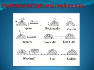
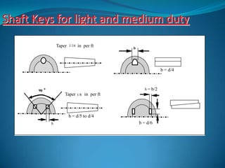
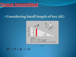
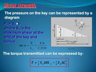
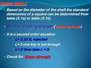
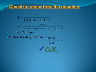
 transmit torque
 keys prevent relative motion,
   Rotary
   axial.
   In some construction they allow
   axial motion
According to shape
 Straight,
 Tapered,
 Rectangular,
 Square,
 Round,
 Dovetail.
according to their intended duty as:
 Light duty keys
 Medium duty
 Heavy duty
b                 b            b


h


        Square      Rectangular     shallow
    b


        Tapered    Two width      Dove tail


        Woodruff       Flat          Saddle
Shaft Keys for light and medium duty
                    Taper 1/16 in per ft      b


                                                                b = d/4


       90
            0                                        h=   b/2
                        Taper 1/8 in per ft


                          b = d/5 to d/4
                b                                 b = d/6
Pulley shaft assembly


                         Pressure
                        distribution
Crushing strength:
  The hub is more rigid than the shaft,
 The shaft will be twisted , the hub will remain
  undistorted.
 The pressure along the key will vary
 Minimum at the free end
 Maximum on the other side.
 Maximum pressure : P1
 The minimum pressure :P2
                                             h
                                             2


 At L the pressure : P.                       D

  At Lo the pressure equals   1P
                                    P

   to zero                                        P2
                                                         
                                   L
                                       L2
                                        L0 = 2.25 D


                                            Fig. (5.4)
Crushing strength Continue

   The pressure can be expressed by:
     P  P1  L tan                                                 h
                                                                      2
   Where
                                                                         D

            ( P1  P 2 )       P1   P1
  tan                                     P

                L2             L0                             P2
                                                                          
                                             L
                                                 L2
                                                  L 0 = 2 .2 5 D


                                                      F ig. (5 .4 )
Torque transmitted

  Considering Small length of key (dL)
                                                     h
                                                     2
                               dl
                                                        D

                  P1
                           P
                                             P2
                                                         
                           L
                                L2
                                    L 0 = 2 .2 5 D


                                     F ig. (5 .4 )


   dT  P  dL  1 D
                 2
Integrating between the limits L = 0 to L2
yields: T  1 P DL  1 DL 2 tan 
                 2    1         2      4     2


   The pressure /unit length =                                                 b
   the crushing stress the area of unit
   length, (Sb 0.5h 1) then,                                               h

         P1  0 . 5 S b h
   Experiments showed that length of key greater than
2.25D is not effective. The pressure at L=2.25D equals zero
and hence,          P1    Sbh
           tan            
                      L0            4 .5 D
  The torque transmitted can be expressed by,
                                       T  1 S b hDL 2     1         2
                                           4               18
                                                                S b hL 2
Shear strength
The pressure on the key can be represented by a
diagram
                                                                            h
                                                                            2
P 1 = Ss b
where Ss is the
                                                                               D

                                      P1

maximum shear at the                               P
                                                                    P2

end of the key and
                                                                                
                                                   L

hence
                                                       L2

               P   Sb                                      L 0 = 2 .2 5 D
        tan      1
                              s


                  L0       2 . 25 D                         F ig. (5 .4 )


The torque transmitted can be expressed by:

                  T  S S bDL 2  S S bL
                           1               1           2
                           2               9           2
Design stages:
  Based on the diameter of the shaft the standard
   dimensions of a square can be determined from
   table (5.1a) or table (5.1b)

  Solve for crushing strength (Obtain key length)

  It is a second order equation
       L> 2.25 D, rejected
       L< 0 one key is not enough

       L< D then take L = D.

  Check for Shear strength
Example:
 Find suitable dimensions of a square key to fit
 into 3 inch diameter shaft. The shaft transmits
       7
      16


 95 hp at a speed of 200 rpm. The key is made of
 steel SAE 1010. Take safety factor of 2.5 and stress
 concentration factor k’ = 1.6
Solution:
  Torque = Power/ angular speed

  Torque = 63030hp
                  N
  Torque = 63030 x 95
                 200

  Torque = 29939 Lb-in

  From table (5.1b), for a shaft with a diameter of inch

                7 7
  Key size :    x
                8 8
Crushing strength
   For steel SAE1010: Ss 20000 psi and Se                    31000 psi
    ,(from table 5.2)
   Hence Sb = 2 x 31000 = 62000 psi
   Taking factor of safety = 2.5 and k’ = 1.6
   Sb = 62000/(1.6x2.5) = 15500 psi
   Crushing strength
                   T  1 S b hDL        
                                            21
                       4            2       18   S b hL   2

            29939  1 15500 x 0 . 875 x 3 . 437 L 2  18 15500 x 0 . 875 L 2
                                                       1                   2
                    4

            29939  11653.6 L 2  753.5 L 2
                                                          2


  
   L = 3.26 or L = 12.21
   The first root is the answer; the second one
      contradicts the condition that L2 < 2.25 D.
      therefore the proper length of the key is 3.5
 Check for shear from the equation:

                              T
        SS 
               L 2 b ( 0 . 5 D  0 . 11 L 2 )
                                  29939
       SS 
               3 . 5 x 0 . 875 ( 0 . 5 x 3 . 437  0 . 113 . 5 )
     Ss = 7331 psi
 Factor of safety in shear =                20000
                                                         2.73
                                              7331

                                  O.K.
Thank You

Shaft keys

  • 2.
     transmit torque keys prevent relative motion,  Rotary  axial.  In some construction they allow axial motion
  • 3.
    According to shape Straight,  Tapered,  Rectangular,  Square,  Round,  Dovetail. according to their intended duty as:  Light duty keys  Medium duty  Heavy duty
  • 4.
    b b b h Square Rectangular shallow b Tapered Two width Dove tail Woodruff Flat Saddle
  • 5.
    Shaft Keys forlight and medium duty Taper 1/16 in per ft b b = d/4 90 0 h= b/2 Taper 1/8 in per ft b = d/5 to d/4 b b = d/6
  • 6.
    Pulley shaft assembly Pressure distribution
  • 7.
    Crushing strength: The hub is more rigid than the shaft, The shaft will be twisted , the hub will remain undistorted. The pressure along the key will vary Minimum at the free end Maximum on the other side. Maximum pressure : P1 The minimum pressure :P2 h 2 At L the pressure : P.  D  At Lo the pressure equals 1P P to zero P2  L L2 L0 = 2.25 D Fig. (5.4)
  • 8.
    Crushing strength Continue  The pressure can be expressed by:  P  P1  L tan  h 2  Where  D ( P1  P 2 ) P1 P1 tan    P L2 L0 P2  L L2 L 0 = 2 .2 5 D F ig. (5 .4 )
  • 9.
    Torque transmitted Considering Small length of key (dL) h 2 dl  D P1 P P2  L L2 L 0 = 2 .2 5 D F ig. (5 .4 ) dT  P  dL  1 D 2
  • 10.
    Integrating between thelimits L = 0 to L2 yields: T  1 P DL  1 DL 2 tan  2 1 2 4 2 The pressure /unit length = b the crushing stress the area of unit length, (Sb 0.5h 1) then, h P1  0 . 5 S b h Experiments showed that length of key greater than 2.25D is not effective. The pressure at L=2.25D equals zero and hence, P1 Sbh tan    L0 4 .5 D The torque transmitted can be expressed by, T  1 S b hDL 2  1 2 4 18 S b hL 2
  • 11.
    Shear strength The pressureon the key can be represented by a diagram h 2 P 1 = Ss b where Ss is the  D P1 maximum shear at the P P2 end of the key and  L hence L2 P Sb L 0 = 2 .2 5 D tan   1  s L0 2 . 25 D F ig. (5 .4 ) The torque transmitted can be expressed by: T  S S bDL 2  S S bL 1 1 2 2 9 2
  • 12.
    Design stages: Based on the diameter of the shaft the standard dimensions of a square can be determined from table (5.1a) or table (5.1b)  Solve for crushing strength (Obtain key length)  It is a second order equation  L> 2.25 D, rejected  L< 0 one key is not enough  L< D then take L = D.  Check for Shear strength
  • 13.
    Example: Find suitabledimensions of a square key to fit into 3 inch diameter shaft. The shaft transmits 7 16 95 hp at a speed of 200 rpm. The key is made of steel SAE 1010. Take safety factor of 2.5 and stress concentration factor k’ = 1.6
  • 14.
    Solution:  Torque= Power/ angular speed  Torque = 63030hp N  Torque = 63030 x 95 200  Torque = 29939 Lb-in  From table (5.1b), for a shaft with a diameter of inch 7 7  Key size : x 8 8
  • 15.
    Crushing strength  For steel SAE1010: Ss 20000 psi and Se 31000 psi ,(from table 5.2)  Hence Sb = 2 x 31000 = 62000 psi  Taking factor of safety = 2.5 and k’ = 1.6  Sb = 62000/(1.6x2.5) = 15500 psi  Crushing strength T  1 S b hDL  21 4 2 18 S b hL 2 29939  1 15500 x 0 . 875 x 3 . 437 L 2  18 15500 x 0 . 875 L 2 1 2 4 29939  11653.6 L 2  753.5 L 2 2   L = 3.26 or L = 12.21  The first root is the answer; the second one contradicts the condition that L2 < 2.25 D. therefore the proper length of the key is 3.5
  • 16.
     Check forshear from the equation: T SS  L 2 b ( 0 . 5 D  0 . 11 L 2 ) 29939 SS  3 . 5 x 0 . 875 ( 0 . 5 x 3 . 437  0 . 113 . 5 )  Ss = 7331 psi  Factor of safety in shear = 20000  2.73 7331 O.K.
  • 17.