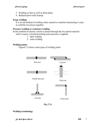
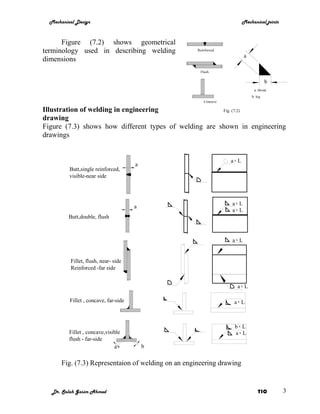
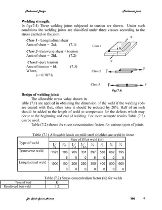
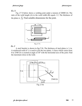
Mechanical Design                                               Mechanical joints


                               Mechanical joints

Welded joints

Methods of joining materials

   1. Mechanical joints
   2. Adhesives
   3. Welding
Uses of welding:
  1. Ship building, industrial and commercial buildings.
  2. Oil pipe -line construction.
  3. Automobile, railways and bridges.
  4. Machine tools.
  5. Farm equipment, home appliances, and air-conditioning units.
  6. Computer components.
  7. Mining equipment.
  8. Boilers, furnaces and vessels.
  9. Maintenance and repair of equipment
Welding and cutting processes:
The most popular processes are:
Oxy-fuel gas welding (OFW)
     A mixture of oxygen and acetylene is used to melt both parent metals.
Shield metal arc welding (SMAW) it is the most popular method because:
   1. High quality weld
   2. Excellent uniformity
   3. High rate
   4. It can be used for variety of materials and thickness.
Gas tungsten arc welding (GTAW):
Advantages:
  1. Clean
  2. High quality weld
  3. No post weld finishing is required
  4. Performed on variety of material
Gas metal arc welding (GMAW):
  1. Fast
  2. Economical


   Dr. Salah Gasim Ahmed                                                 YIC          1
Mechanical Design                                                    Mechanical joints


   3. Welding on thin as well as thick plates
   4. Reduced post-weld cleanup
Forge welding:
  It is an old method of welding where manual or machine hammering is used
  to weld the two pieces together
Pressure welding or resistance welding
In this method an electric current is passed through the two parent material
    until it causes a localized melting and a pressure is applied.
                  1. Spot welding
                  2. seam welding

Welding joints:
     Figure(7.1) shows main types of welding joints


                             Butt joint                 Lap joint


                           Double butt joint
                                                        Edje joint


                              Tee joint                 Corner joint


                                           Fig. (7.1)


Welding terminology


   Dr. Salah Gasim Ahmed                                                      YIC          2
Mechanical Design                                                      Mechanical joints


      Figure (7.2) shows geometrical
terminology used in describing welding               Reinforced
                                                                         a
dimensions
                                                      Flush

                                                                                      b
                                                                              a: throat
                                                                             b: leg
                                                        Concave

Illustration of welding in engineering                 Fig. (7.2)
drawing
Figure (7.3) shows how different types of welding are shown in engineering
drawings


                                                                  ax L
                                       a
          Butt,single reinforced,
          visible-near side


                                                                  ax L
                                       a
                                                                  ax L
          Butt,double, flush


                                                                  ax L


          Fillet, flush, near- side
          Reinforced -far side


                                                                    ax L

          Fillet , concave, far-side                               ax L


                                                                   bx L
          Fillet , concave,visible                                 ax L
          flush - far-side
                               a           b


       Fig. (7.3) Representaion of welding on an engineering drawing


   Dr. Salah Gasim Ahmed                                                         YIC         3
Mechanical Design                                                              Mechanical joints


            Welding strength:
            In fig.(7.4) Three welding joints subjected to tension are shown. Under such
            conditions the welding joints are classified under three classes according to the
            stress exerted on the joint:
                                                                                                     F
                Class 1 - Longitudinal shear
                Area of shear = 2aL          (7.1)                 Class 1
                                                                                         h
                Class 2- transverse shear + tension
                Area of shear = 2hL           (7.2)
                Class3 -pure tension                                             F
                Area of tension = hL                (7.3)
                Where,                                            Class 2
                      a = 0.707 h

                                                                  Class 3
                                                                                  Fig.(7.4)
            Design of welding joint:
                   The allowable stress value shown in
            table (7.1) are applied in obtaining the dimension of the weld if the welding rods
            are coated with flux, other wise it should be reduced by 20%. Half of an inch
            should be added to the length of weld to compensate for the defects which may
            occur at the beginning and end of welding. For more accurate results Table (7.3)
            can be used.
                   Table (7.2) shows the stress concentration factors for various types of joints.

                  Table (7.1) Allowable loads on mild steel shielded arc-weld in shear
                                           Size of fillet weld (in)
          Type of weld
                               1     3
                                      16   1 516 3 8 1 2 5 8 3 4
                                 8           4
          Transverse weld     1325 198 265 331 397 530 662 795
                                                5      0      0     5        0       0        0
          Longitudinal weld        1000       150    200    250   300   400      500     600
                                                0      0      0     0        0       0        0

                              Table (7.2) Stress concentration factor (K) for welds
        Type of load                     K
Reinforced butt weld                    1.2


                Dr. Salah Gasim Ahmed                                                                YIC          4
Mechanical Design                                                                       Mechanical joints


Toe of transverse fillet weld             1.5
End of longitudinal weld                  2.7
T-butt joint with sharp corners            2
                              Table (7.3) Strength of Shielded-Arc Flush Steel Welds
                                    Safety factor 2        Safety factor 2         Safety factor 2.75
             Kind of Stress              Static load   Load varies from 0 to F   Load varies from -F to +F
             Tension                      16000                14500                      8000
             Compression                  18000                16000                      8000
             Bending                      18000                16000                      9000
             Shear                        11000                10000                      5000
             Shear and tension            11000                10000                      5000


              Eccentric loads:
                    When the load on a welded joint is applied eccentrically, the welds will be
              subjected to a combination of shear caused by the direct load and shear caused by
              torque. The state of stress in such a joint is complicated; and in order to determine
              the value of the significant stress even approximately, it is necessary to assume


                                                                  l


                                                                       O1

                                     S
                                                                      r1
                                                       r

                                                              T

                                                                            O


                                                Fig.(7.5) Eccentric loading
              that the torsional shear stress at any point is proportional to its distance from
              centroid of all weld areas.
              If the weld shown in fig.(7.5) is one of several forming a joint with the centroid of
              weld areas at O, the torsional shear stress s on an element dA of the weld will be
              perpendicular to r and can be expressed as:
                           s = nr
              where n is a constant of proportionality and r the distance from the element to O.
              The external torque T is equal to the torque resistance of the element, sdAr,
              integrated over all the welds in the joint. Thus,

                 Dr. Salah Gasim Ahmed                                                                         YIC          5
Mechanical Design                                                     Mechanical joints


               T = ∫ sdAr

              T = n ∫ r 2 dA = nJ
Where J is the polar moment of inertia with respect to O for all elements of the
weld. The stress in any element can be found by the relation:
                      Tr
               s =                                                         (7.4)
                      J

Example(1)
       Determine the load which an arc-welded joint of class 1, fig.(7.4), can safely
carry if it joints 0.375 in plates and each fillet is 4.5 in long and reinforced. The
load varies from zero to a certain maximum value.

Solution:
The cross-sectional area of a flush fillet weld resisting shear would be a(l-0.5), and
the area of a fully reinforced fillet may be taken as 1.2 a(l-0.5). Thus the total
cross-sectional area of both fillets is:
A1 = 0.707h x 1.2 a(l-0.5)x2 = 0.707 x0.375 x 1.2 x (4.5 -0.5) x 2 = 2.55
The working stress from table (7.) is Ss = 10000 psi, the safe load is,
F1 = A1Ss = 2.55 x 10000 = 25,500 lb

Example(2):
       Determine the loads which welded joints of class 2 and class 3 Fig.(7.4) can
safely carry using the conditions and data of the previous example and compare
them with the strength of the strip.

Solution:
In the joint of class 2 the section area in tension is equal to that in shear. Therefore
the strength in shear is smaller. The area of the weld is:
A2 = 0.375 (4.5 – 0.5) x 2 = 3 in2
And the safe load with S =10000 psi is:
F2 = A2xSs = 3 x 10000 = 30000 lb

 Thus one may say that class 2 joint is considerable stronger than a class 1 joint
                       although they are not quite comparable.
In the joint of class 3 the area of the dangerous section with a reinforced joint is :
A3 = 0.375 x 1.2 x (4.5 -0.5) = 1.8 in2
From table (7.) allowable stress in tension is S = 14500 psi and the safe load is:
F3= A3S= 1.8 x 14500 = 26100 lb


   Dr. Salah Gasim Ahmed                                                       YIC          6
Mechanical Design                                                  Mechanical joints


The class 1 joint is the weakest one, although its strength is only 2% below what
                                    of class 3

     Assume that the base metal is SAE 1010 steel with endurance limit of S e=
14500 psi. The safe load amplitude with a safety factor of 2 is:
             0.375 x4.5 x14500
       Fa=                     = 12200lb
                     2
Hence Fmax = 2Fa=24400 lb


                                                           2200 lb
                           2 in     2 in       4.5 in
                6 in


                                   O


                                               ¼ in weld


                                  Fig. (7.6)

          Thus arc welded joints are theoretically stronger than the strip

Example(3):
       Determine the maximum stress in the reinforced weld of the bracket plate in
fig.(7.6) . Assume that the load varies from zero to the maximum value
Solution:
………………………………………………………………………………….
………………………………………………………………………………….
………………………………………………………………………………….
………………………………………………………………………………….
………………………………………………………………………………….
………………………………………………………………………………….
………………………………………………………………………………….


   Dr. Salah Gasim Ahmed                                                    YIC          7
Mechanical Design          Mechanical joints


………………………………………………………………………………….
………………………………………………………………………………….
………………………………………………………………………………….
………………………………………………………………………………….
………………………………………………………………………………….
………………………………………………………………………………….
………………………………………………………………………………….
………………………………………………………………………………….
………………………………………………………………………………….
………………………………………………………………………………….
………………………………………………………………………………….
………………………………………………………………………………….
………………………………………………………………………………….
………………………………………………………………………………….
………………………………………………………………………………….
………………………………………………………………………………….
………………………………………………………………………………….
………………………………………………………………………………….
………………………………………………………………………………….
………………………………………………………………………………….
………………………………………………………………………………….
………………………………………………………………………………….
………………………………………………………………………………….
………………………………………………………………………………….
………………………………………………………………………………….


 Dr. Salah Gasim Ahmed            YIC          8
Mechanical Design          Mechanical joints


………………………………………………………………………………….


 Dr. Salah Gasim Ahmed            YIC          9
Mechanical Design                                                        Mechanical joints


Ex. 1:
      Fig. (7.7) below shows a welding joint under a tension of 20000 Lb. The
ratio of the weld length (A) to the weld width (B) equals 1.5. The thickness of
the plates is 3 8 Find suitable dimensions for the joint.


                                           A


                      F        B                             F


                                                         F
                          F


                                   Fig. (7.7)
Ex. 2
      A steel bracket is shown in fig.(7.8). The thickness of steel plates is ¼ in.
A reinforced weld of ¼ is used to join the two plates. A force which varies from
0 to 2540 Lb is exerted at angle of 30 0 with the horizontal axis of the joint. Find
the maximum stress in the weld.


                              2 in 2 in        4.5 in


              6 in                 O
                                                                 300


                                                                 2540 Lb
                                                1/4 in
                                                weld
                                          Fig. (7.8)


   Dr. Salah Gasim Ahmed                                                          YIC          10

MET 304 Mechanical joints welded

  • 1.
    Mechanical Design Mechanical joints Mechanical joints Welded joints Methods of joining materials 1. Mechanical joints 2. Adhesives 3. Welding Uses of welding: 1. Ship building, industrial and commercial buildings. 2. Oil pipe -line construction. 3. Automobile, railways and bridges. 4. Machine tools. 5. Farm equipment, home appliances, and air-conditioning units. 6. Computer components. 7. Mining equipment. 8. Boilers, furnaces and vessels. 9. Maintenance and repair of equipment Welding and cutting processes: The most popular processes are: Oxy-fuel gas welding (OFW) A mixture of oxygen and acetylene is used to melt both parent metals. Shield metal arc welding (SMAW) it is the most popular method because: 1. High quality weld 2. Excellent uniformity 3. High rate 4. It can be used for variety of materials and thickness. Gas tungsten arc welding (GTAW): Advantages: 1. Clean 2. High quality weld 3. No post weld finishing is required 4. Performed on variety of material Gas metal arc welding (GMAW): 1. Fast 2. Economical Dr. Salah Gasim Ahmed YIC 1
  • 2.
    Mechanical Design Mechanical joints 3. Welding on thin as well as thick plates 4. Reduced post-weld cleanup Forge welding: It is an old method of welding where manual or machine hammering is used to weld the two pieces together Pressure welding or resistance welding In this method an electric current is passed through the two parent material until it causes a localized melting and a pressure is applied. 1. Spot welding 2. seam welding Welding joints: Figure(7.1) shows main types of welding joints Butt joint Lap joint Double butt joint Edje joint Tee joint Corner joint Fig. (7.1) Welding terminology Dr. Salah Gasim Ahmed YIC 2
  • 3.
    Mechanical Design Mechanical joints Figure (7.2) shows geometrical terminology used in describing welding Reinforced a dimensions Flush b a: throat b: leg Concave Illustration of welding in engineering Fig. (7.2) drawing Figure (7.3) shows how different types of welding are shown in engineering drawings ax L a Butt,single reinforced, visible-near side ax L a ax L Butt,double, flush ax L Fillet, flush, near- side Reinforced -far side ax L Fillet , concave, far-side ax L bx L Fillet , concave,visible ax L flush - far-side a b Fig. (7.3) Representaion of welding on an engineering drawing Dr. Salah Gasim Ahmed YIC 3
  • 4.
    Mechanical Design Mechanical joints Welding strength: In fig.(7.4) Three welding joints subjected to tension are shown. Under such conditions the welding joints are classified under three classes according to the stress exerted on the joint: F Class 1 - Longitudinal shear Area of shear = 2aL (7.1) Class 1 h Class 2- transverse shear + tension Area of shear = 2hL (7.2) Class3 -pure tension F Area of tension = hL (7.3) Where, Class 2 a = 0.707 h Class 3 Fig.(7.4) Design of welding joint: The allowable stress value shown in table (7.1) are applied in obtaining the dimension of the weld if the welding rods are coated with flux, other wise it should be reduced by 20%. Half of an inch should be added to the length of weld to compensate for the defects which may occur at the beginning and end of welding. For more accurate results Table (7.3) can be used. Table (7.2) shows the stress concentration factors for various types of joints. Table (7.1) Allowable loads on mild steel shielded arc-weld in shear Size of fillet weld (in) Type of weld 1 3 16 1 516 3 8 1 2 5 8 3 4 8 4 Transverse weld 1325 198 265 331 397 530 662 795 5 0 0 5 0 0 0 Longitudinal weld 1000 150 200 250 300 400 500 600 0 0 0 0 0 0 0 Table (7.2) Stress concentration factor (K) for welds Type of load K Reinforced butt weld 1.2 Dr. Salah Gasim Ahmed YIC 4
  • 5.
    Mechanical Design Mechanical joints Toe of transverse fillet weld 1.5 End of longitudinal weld 2.7 T-butt joint with sharp corners 2 Table (7.3) Strength of Shielded-Arc Flush Steel Welds Safety factor 2 Safety factor 2 Safety factor 2.75 Kind of Stress Static load Load varies from 0 to F Load varies from -F to +F Tension 16000 14500 8000 Compression 18000 16000 8000 Bending 18000 16000 9000 Shear 11000 10000 5000 Shear and tension 11000 10000 5000 Eccentric loads: When the load on a welded joint is applied eccentrically, the welds will be subjected to a combination of shear caused by the direct load and shear caused by torque. The state of stress in such a joint is complicated; and in order to determine the value of the significant stress even approximately, it is necessary to assume l O1 S r1 r T O Fig.(7.5) Eccentric loading that the torsional shear stress at any point is proportional to its distance from centroid of all weld areas. If the weld shown in fig.(7.5) is one of several forming a joint with the centroid of weld areas at O, the torsional shear stress s on an element dA of the weld will be perpendicular to r and can be expressed as: s = nr where n is a constant of proportionality and r the distance from the element to O. The external torque T is equal to the torque resistance of the element, sdAr, integrated over all the welds in the joint. Thus, Dr. Salah Gasim Ahmed YIC 5
  • 6.
    Mechanical Design Mechanical joints T = ∫ sdAr T = n ∫ r 2 dA = nJ Where J is the polar moment of inertia with respect to O for all elements of the weld. The stress in any element can be found by the relation: Tr s = (7.4) J Example(1) Determine the load which an arc-welded joint of class 1, fig.(7.4), can safely carry if it joints 0.375 in plates and each fillet is 4.5 in long and reinforced. The load varies from zero to a certain maximum value. Solution: The cross-sectional area of a flush fillet weld resisting shear would be a(l-0.5), and the area of a fully reinforced fillet may be taken as 1.2 a(l-0.5). Thus the total cross-sectional area of both fillets is: A1 = 0.707h x 1.2 a(l-0.5)x2 = 0.707 x0.375 x 1.2 x (4.5 -0.5) x 2 = 2.55 The working stress from table (7.) is Ss = 10000 psi, the safe load is, F1 = A1Ss = 2.55 x 10000 = 25,500 lb Example(2): Determine the loads which welded joints of class 2 and class 3 Fig.(7.4) can safely carry using the conditions and data of the previous example and compare them with the strength of the strip. Solution: In the joint of class 2 the section area in tension is equal to that in shear. Therefore the strength in shear is smaller. The area of the weld is: A2 = 0.375 (4.5 – 0.5) x 2 = 3 in2 And the safe load with S =10000 psi is: F2 = A2xSs = 3 x 10000 = 30000 lb Thus one may say that class 2 joint is considerable stronger than a class 1 joint although they are not quite comparable. In the joint of class 3 the area of the dangerous section with a reinforced joint is : A3 = 0.375 x 1.2 x (4.5 -0.5) = 1.8 in2 From table (7.) allowable stress in tension is S = 14500 psi and the safe load is: F3= A3S= 1.8 x 14500 = 26100 lb Dr. Salah Gasim Ahmed YIC 6
  • 7.
    Mechanical Design Mechanical joints The class 1 joint is the weakest one, although its strength is only 2% below what of class 3 Assume that the base metal is SAE 1010 steel with endurance limit of S e= 14500 psi. The safe load amplitude with a safety factor of 2 is: 0.375 x4.5 x14500 Fa= = 12200lb 2 Hence Fmax = 2Fa=24400 lb 2200 lb 2 in 2 in 4.5 in 6 in O ¼ in weld Fig. (7.6) Thus arc welded joints are theoretically stronger than the strip Example(3): Determine the maximum stress in the reinforced weld of the bracket plate in fig.(7.6) . Assume that the load varies from zero to the maximum value Solution: …………………………………………………………………………………. …………………………………………………………………………………. …………………………………………………………………………………. …………………………………………………………………………………. …………………………………………………………………………………. …………………………………………………………………………………. …………………………………………………………………………………. Dr. Salah Gasim Ahmed YIC 7
  • 8.
    Mechanical Design Mechanical joints …………………………………………………………………………………. …………………………………………………………………………………. …………………………………………………………………………………. …………………………………………………………………………………. …………………………………………………………………………………. …………………………………………………………………………………. …………………………………………………………………………………. …………………………………………………………………………………. …………………………………………………………………………………. …………………………………………………………………………………. …………………………………………………………………………………. …………………………………………………………………………………. …………………………………………………………………………………. …………………………………………………………………………………. …………………………………………………………………………………. …………………………………………………………………………………. …………………………………………………………………………………. …………………………………………………………………………………. …………………………………………………………………………………. …………………………………………………………………………………. …………………………………………………………………………………. …………………………………………………………………………………. …………………………………………………………………………………. …………………………………………………………………………………. …………………………………………………………………………………. Dr. Salah Gasim Ahmed YIC 8
  • 9.
    Mechanical Design Mechanical joints …………………………………………………………………………………. Dr. Salah Gasim Ahmed YIC 9
  • 10.
    Mechanical Design Mechanical joints Ex. 1: Fig. (7.7) below shows a welding joint under a tension of 20000 Lb. The ratio of the weld length (A) to the weld width (B) equals 1.5. The thickness of the plates is 3 8 Find suitable dimensions for the joint. A F B F F F Fig. (7.7) Ex. 2 A steel bracket is shown in fig.(7.8). The thickness of steel plates is ¼ in. A reinforced weld of ¼ is used to join the two plates. A force which varies from 0 to 2540 Lb is exerted at angle of 30 0 with the horizontal axis of the joint. Find the maximum stress in the weld. 2 in 2 in 4.5 in 6 in O 300 2540 Lb 1/4 in weld Fig. (7.8) Dr. Salah Gasim Ahmed YIC 10
  • 11.
    Mechanical Design Mechanical joints Ex. 1: Fig. (7.7) below shows a welding joint under a tension of 20000 Lb. The ratio of the weld length (A) to the weld width (B) equals 1.5. The thickness of the plates is 3 8 Find suitable dimensions for the joint. A F B F F F Fig. (7.7) Ex. 2 A steel bracket is shown in fig.(7.8). The thickness of steel plates is ¼ in. A reinforced weld of ¼ is used to join the two plates. A force which varies from 0 to 2540 Lb is exerted at angle of 30 0 with the horizontal axis of the joint. Find the maximum stress in the weld. 2 in 2 in 4.5 in 6 in O 300 2540 Lb 1/4 in weld Fig. (7.8) Dr. Salah Gasim Ahmed YIC 10
  • 12.
    Mechanical Design Mechanical joints Ex. 1: Fig. (7.7) below shows a welding joint under a tension of 20000 Lb. The ratio of the weld length (A) to the weld width (B) equals 1.5. The thickness of the plates is 3 8 Find suitable dimensions for the joint. A F B F F F Fig. (7.7) Ex. 2 A steel bracket is shown in fig.(7.8). The thickness of steel plates is ¼ in. A reinforced weld of ¼ is used to join the two plates. A force which varies from 0 to 2540 Lb is exerted at angle of 30 0 with the horizontal axis of the joint. Find the maximum stress in the weld. 2 in 2 in 4.5 in 6 in O 300 2540 Lb 1/4 in weld Fig. (7.8) Dr. Salah Gasim Ahmed YIC 10