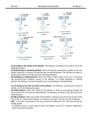
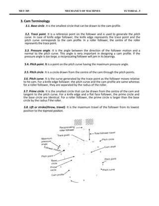
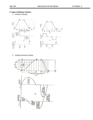
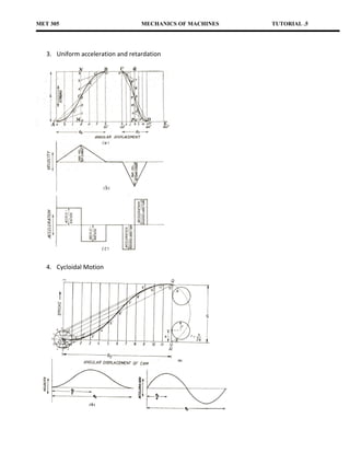
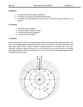
MET 305                                 MECHANICS OF MACHINES                              TUTORIAL .5


Student Name & No.________________________________ Date:___________________

Section: _________________________________________ Score: ___________________

                                               Cams
1. Introduction
A cam is a rotating machine element, which gives reciprocating or oscillating motion to another
element known as follower. The cam and the follower have a line contact and constitute a
higher pair. The cams are usually rotated at uniform speed by a shaft, but the follower motion
is predetermined and will be according to the shape of the cam The cam and follower is one of
the simplest as well as one of the most important mechanisms found in machinery today. The
cams are widely used for the inlet and exhaust valves of internal combustion engines,
automatic attachment of machineries, paper cutting machines, spinning and weaving textile
machineries, feed mechanism of automatic lathes etc.

2. Classification of Followers
The followers may be classified as discussed below:
2.1. According to the surface in contact.
The followers, according to the surface in contact, are as follows:

(a) Knife edge follower. When the contacting end of the follower has a sharp knife-edge, it is
knife-edge follower, as shown in Fig. (a). The sliding motion takes place between the surfaces
(i.e. the knife-edge and the cam surface). This is seldom used in practice because the small area
of contacting surface results in excessive wear. In knife-edge followers, a considerable side
thrust exists between the follower and the guide.
(b) Roller follower. When the contacting end of the follower is a roller, it is called a roller
follower, as shown in Fig.(b). Since the rolling motion takes place between the contacting
surfaces (i.e. the roller and the cam), therefore the rate of wear is greatly reduced. In roller followers
also the side thrust exists between the follower and the guide. The roller followers are
extensively used where more space is available such as in stationary gas and oil engines and
aircraft engines.
(c) Flat faced or mushroom follower. When the contacting end of the follower is a perfectly flat
face, it is called a flat-faced follower, as shown in Fig.(c). It may be noted that the side thrust
between the follower and the guide is much reduced in case of flat-faced followers. The only
side thrust is due to friction between the contact surfaces of the follower and the cam. The
relative motion between these surfaces is largely of sliding nature but wear may be reduced by
off-setting the axis of the follower, as shown in Fig.(f) so that when the cam rotates, the
follower also rotates about its own axis. The flat faced followers are generally used where space
is limited such as in cams which operate the valves of automobile engines.
Note : When the flat faced follower is circular, it is then called a mushroom follower.
(d) Spherical faced follower. When the contacting end of the follower is of spherical shape, it is
called a spherical faced follower, as shown in Fig.(d). It may be noted that when a flat-faced
follower is used in automobile engines, high surface stresses are produced. In order to minimize
these stresses, the flat end of the follower is machined to a spherical shape.
MET 305                               MECHANICS OF MACHINES                             TUTORIAL .5


2.2.According to the motion of the follower. The followers, according to its motion, are of the
following two types
(a) Reciprocating or translating follower. When the follower reciprocates in guides as the cam
rotates uniformly, it is known as reciprocating or translating follower. The followers as shown in
Fig. 20.1 (a) to (d) are all reciprocating or translating followers.
(b) Oscillating or rotating follower. When the uniform rotary motion of the cam is converted
into predetermined oscillatory motion of the follower, it is called oscillating or rotating
follower. The follower, as shown in Fig 20.1 (e), is an oscillating or rotating follower.

2.3. According to the path of motion of the follower. The followers, according to its path of
motion, are of the following two types:
(a) Radial follower. When the motion of the follower is along an axis passing through the
centre of the cam, it is known as radial follower. The followers, as shown in Fig. (a) to (e) are all
radial followers.
(b) Off-set follower. When the motion of the follower is along an axis away from the axis of the
cam centre, it is called off-set follower. The follower, as shown in Fig. (f), is an off-set follower.
Note : In all cases, the follower must be constrained to follow the cam. This may be done by
springs, gravity
  or hydraulic means. In some types of cams, the follower may ride in a groove. important in
  order to draw the cam profile.
MET 305                              MECHANICS OF MACHINES                              TUTORIAL .5


 3. Cam Terminology
    3.1. Base circle. It is the smallest circle that can be drawn to the cam profile.

    3.2. Trace point. It is a reference point on the follower and is used to generate the pitch
    curve. In case of knife edge follower, the knife edge represents the trace point and the
    pitch curve corresponds to the cam profile. In a roller follower, the centre of the roller
    represents the trace point.

   3.3. Pressure angle. It is the angle between the direction of the follower motion and a
   normal to the pitch curve. This angle is very important in designing a cam profile. If the
   pressure angle is too large, a reciprocating follower will jam in its bearings.

   3.4. Pitch point. It is a point on the pitch curve having the maximum pressure angle.

   3.5. Pitch circle. It is a circle drawn from the centre of the cam through the pitch points.

   3.6. Pitch curve. It is the curve generated by the trace point as the follower moves relative
   to he cam. For a knife edge follower, the pitch curve and the cam profile are same whereas
   for a roller follower, they are separated by the radius of the roller.

   3.7. Prime circle. It is the smallest circle that can be drawn from the centre of the cam and
   tangent to the pitch curve. For a knife edge and a flat face follower, the prime circle and
   the base circle are identical. For a roller follower, the prime circle is larger than the base
   circle by the radius f the roller.

   3.8. Lift or stroke(throw, travel). It is the maximum travel of the follower from its lowest
   position to the topmost position.
MET 305                        MECHANICS OF MACHINES   TUTORIAL .5


4. Types of follower motions
    1. Uniform velocity


   2. Simple harmonic motion
MET 305                            MECHANICS OF MACHINES   TUTORIAL .5


   3. Uniform acceleration and retardation


   4. Cycloidal Motion
MET 305                               MECHANICS OF MACHINES                          TUTORIAL .5


5. Objective

          a. To understand different types of followers
          b. To analyze various types of follower displacements
          c. To analyze and draw different types of cams for different types of followers and
             motions

6. Procedure

           1.   Check the type of follower.
           2.   Study the type of follower motion.
           3.   Draw the displacement diagram.
           4.   Construct the cam profile.

7. Problems

1. Draw the profile of a disc cam to give uniform motion (uniform velocity) during outstroke of 25
mm to a knife edge follower during the first half of the cam revolution. The return of the cam also
takes place with uniform motion (uniform velocity) during the remaining half of the cam
revolution. Minimum radius of the cam is 25 mm. Draw the shaft on which the cam is mounted
showing the position of the key. Shaft diameter - 25 mm. The axis of the knife edge follower passes
through the axis of the cam.
MET 305                                 MECHANICS OF MACHINES                             TUTORIAL .5


2. Draw the cam profile for cam with roller reciprocating follower. The axis of the follower passes
through the axis of the cam and rotates anticlockwise. Particulars of the cam and the follower motion
are the following:
       Roller diameter                      = 5 mm
       Minimum radius of the cam            = 20 mm
       Total lift                           = 25 mm.
The cam has to lift the follower with simple harmonic motion during 180° of cam rotation, then allow
the follower to drop suddenly halfway, and further return the follower with uniform velocity
during the remaining 180° of cam rotation. Show the position of key on the shaft to which the
cam is mounted. Determine the maximum velocity and maximum acceleration on the outstroke, if
the cam rotates at a uniform speed of 100 r.p.m.

Answer
MET 305                                MECHANICS OF MACHINES                             TUTORIAL .5


3.. Cam with 30 mm as minimum diameter is rotating clockwise at a uniform speed of 1200
r.p.m. clockwise and has to give the motion to the roller follower 10 mm diameter as defined
below :
         (i ) Follower to complete outward stroke of 25 mm during 120° of cam rotation with
         equal uniform acceleration and retardation.
       (ii) Follower to dwell for 60° of cam rotation.
        (iii) Follower to return to its initial position during 90° of cam, rotation with equal uniform
      acceleration and retardation
      (iv) Follower to dwell for the remaining 90° of cam rotation.
       Layout the cam profile when:
       (a) the roller follower axis passes through the axis of the cam ;
       (b) the roller follower axis is offset to right by 5 mm.
Determine the uniform acceleration of the follower on the outstroke and the return stroke, and
also the maximum velocity of the follower during outstroke and the return stroke.
                                                                                 Answer
MET 305                               MECHANICS OF MACHINES                          TUTORIAL .5


4. Determine the profile of cam to give oscillatory motion to the follower, with uniform angular
velocity about its pivot. One oscillation is completed in one revolution of the cam. The distance
between the cam centre and the pivot of the follower is 50 mm. The base circle diameter is 40
mm. Angle of oscillation is 29°. The length of the oscillating lever = 50 mm with roller of 5 mm
diameter at the end. The cam rotates anticlockwise.
Answer
MET 305                                  MECHANICS OF MACHINES                              TUTORIAL .5


5. It is required to set out the profile of a cam to give the following motion to the reciprocating
follower with a flat mushroom contact face:
    (i) Follower to have a stroke of 20 mm during 120° of cam rotation;
    (ii) Follower to dwell for 30° of cam rotation (ii) follower to return to its initial position during
    120° of cam rotation;
    (iv) Follower to dwell for remaining 90° of cam rotation. Cam rotates anticlockwise

Answer
MET 305                              MECHANICS OF MACHINES                          TUTORIAL .5


6. It is required to set out the profile of a cam to give the following motion to the follower:
    (i) Follower to move outwards through 31.4 mm during 180° of cam rotation, with cycloidal
    motion;
    (ii) Follower to return with cycloidal motion during 180° of cam rotation.
Determine the maximum velocity and acceleration of the follower during the outstroke when the
cam rotates at 2400 r.p.m. clockwise. The base circle of the cam is 30 mm diameter and the roller
diameter of the follower is 10 mm. The axis of the roller is offset by 7.5 mm to the right.
MET 305                            MECHANICS OF MACHINES                       TUTORIAL .5


    10. Conclusion

    This tutorial enables the student to construct any type of cam profile for any mechanism
    design.
MET 305                            MECHANICS OF MACHINES                       TUTORIAL .5


    10. Conclusion

    This tutorial enables the student to construct any type of cam profile for any mechanism
    design.

Met 305 tutorial_6_cams

  • 1.
    MET 305 MECHANICS OF MACHINES TUTORIAL .5 Student Name & No.________________________________ Date:___________________ Section: _________________________________________ Score: ___________________ Cams 1. Introduction A cam is a rotating machine element, which gives reciprocating or oscillating motion to another element known as follower. The cam and the follower have a line contact and constitute a higher pair. The cams are usually rotated at uniform speed by a shaft, but the follower motion is predetermined and will be according to the shape of the cam The cam and follower is one of the simplest as well as one of the most important mechanisms found in machinery today. The cams are widely used for the inlet and exhaust valves of internal combustion engines, automatic attachment of machineries, paper cutting machines, spinning and weaving textile machineries, feed mechanism of automatic lathes etc. 2. Classification of Followers The followers may be classified as discussed below: 2.1. According to the surface in contact. The followers, according to the surface in contact, are as follows: (a) Knife edge follower. When the contacting end of the follower has a sharp knife-edge, it is knife-edge follower, as shown in Fig. (a). The sliding motion takes place between the surfaces (i.e. the knife-edge and the cam surface). This is seldom used in practice because the small area of contacting surface results in excessive wear. In knife-edge followers, a considerable side thrust exists between the follower and the guide. (b) Roller follower. When the contacting end of the follower is a roller, it is called a roller follower, as shown in Fig.(b). Since the rolling motion takes place between the contacting surfaces (i.e. the roller and the cam), therefore the rate of wear is greatly reduced. In roller followers also the side thrust exists between the follower and the guide. The roller followers are extensively used where more space is available such as in stationary gas and oil engines and aircraft engines. (c) Flat faced or mushroom follower. When the contacting end of the follower is a perfectly flat face, it is called a flat-faced follower, as shown in Fig.(c). It may be noted that the side thrust between the follower and the guide is much reduced in case of flat-faced followers. The only side thrust is due to friction between the contact surfaces of the follower and the cam. The relative motion between these surfaces is largely of sliding nature but wear may be reduced by off-setting the axis of the follower, as shown in Fig.(f) so that when the cam rotates, the follower also rotates about its own axis. The flat faced followers are generally used where space is limited such as in cams which operate the valves of automobile engines. Note : When the flat faced follower is circular, it is then called a mushroom follower. (d) Spherical faced follower. When the contacting end of the follower is of spherical shape, it is called a spherical faced follower, as shown in Fig.(d). It may be noted that when a flat-faced follower is used in automobile engines, high surface stresses are produced. In order to minimize these stresses, the flat end of the follower is machined to a spherical shape.
  • 2.
    MET 305 MECHANICS OF MACHINES TUTORIAL .5 2.2.According to the motion of the follower. The followers, according to its motion, are of the following two types (a) Reciprocating or translating follower. When the follower reciprocates in guides as the cam rotates uniformly, it is known as reciprocating or translating follower. The followers as shown in Fig. 20.1 (a) to (d) are all reciprocating or translating followers. (b) Oscillating or rotating follower. When the uniform rotary motion of the cam is converted into predetermined oscillatory motion of the follower, it is called oscillating or rotating follower. The follower, as shown in Fig 20.1 (e), is an oscillating or rotating follower. 2.3. According to the path of motion of the follower. The followers, according to its path of motion, are of the following two types: (a) Radial follower. When the motion of the follower is along an axis passing through the centre of the cam, it is known as radial follower. The followers, as shown in Fig. (a) to (e) are all radial followers. (b) Off-set follower. When the motion of the follower is along an axis away from the axis of the cam centre, it is called off-set follower. The follower, as shown in Fig. (f), is an off-set follower. Note : In all cases, the follower must be constrained to follow the cam. This may be done by springs, gravity or hydraulic means. In some types of cams, the follower may ride in a groove. important in order to draw the cam profile.
  • 3.
    MET 305 MECHANICS OF MACHINES TUTORIAL .5 3. Cam Terminology 3.1. Base circle. It is the smallest circle that can be drawn to the cam profile. 3.2. Trace point. It is a reference point on the follower and is used to generate the pitch curve. In case of knife edge follower, the knife edge represents the trace point and the pitch curve corresponds to the cam profile. In a roller follower, the centre of the roller represents the trace point. 3.3. Pressure angle. It is the angle between the direction of the follower motion and a normal to the pitch curve. This angle is very important in designing a cam profile. If the pressure angle is too large, a reciprocating follower will jam in its bearings. 3.4. Pitch point. It is a point on the pitch curve having the maximum pressure angle. 3.5. Pitch circle. It is a circle drawn from the centre of the cam through the pitch points. 3.6. Pitch curve. It is the curve generated by the trace point as the follower moves relative to he cam. For a knife edge follower, the pitch curve and the cam profile are same whereas for a roller follower, they are separated by the radius of the roller. 3.7. Prime circle. It is the smallest circle that can be drawn from the centre of the cam and tangent to the pitch curve. For a knife edge and a flat face follower, the prime circle and the base circle are identical. For a roller follower, the prime circle is larger than the base circle by the radius f the roller. 3.8. Lift or stroke(throw, travel). It is the maximum travel of the follower from its lowest position to the topmost position.
  • 4.
    MET 305 MECHANICS OF MACHINES TUTORIAL .5 4. Types of follower motions 1. Uniform velocity 2. Simple harmonic motion
  • 5.
    MET 305 MECHANICS OF MACHINES TUTORIAL .5 3. Uniform acceleration and retardation 4. Cycloidal Motion
  • 6.
    MET 305 MECHANICS OF MACHINES TUTORIAL .5 5. Objective a. To understand different types of followers b. To analyze various types of follower displacements c. To analyze and draw different types of cams for different types of followers and motions 6. Procedure 1. Check the type of follower. 2. Study the type of follower motion. 3. Draw the displacement diagram. 4. Construct the cam profile. 7. Problems 1. Draw the profile of a disc cam to give uniform motion (uniform velocity) during outstroke of 25 mm to a knife edge follower during the first half of the cam revolution. The return of the cam also takes place with uniform motion (uniform velocity) during the remaining half of the cam revolution. Minimum radius of the cam is 25 mm. Draw the shaft on which the cam is mounted showing the position of the key. Shaft diameter - 25 mm. The axis of the knife edge follower passes through the axis of the cam.
  • 7.
    MET 305 MECHANICS OF MACHINES TUTORIAL .5 2. Draw the cam profile for cam with roller reciprocating follower. The axis of the follower passes through the axis of the cam and rotates anticlockwise. Particulars of the cam and the follower motion are the following: Roller diameter = 5 mm Minimum radius of the cam = 20 mm Total lift = 25 mm. The cam has to lift the follower with simple harmonic motion during 180° of cam rotation, then allow the follower to drop suddenly halfway, and further return the follower with uniform velocity during the remaining 180° of cam rotation. Show the position of key on the shaft to which the cam is mounted. Determine the maximum velocity and maximum acceleration on the outstroke, if the cam rotates at a uniform speed of 100 r.p.m. Answer
  • 8.
    MET 305 MECHANICS OF MACHINES TUTORIAL .5 3.. Cam with 30 mm as minimum diameter is rotating clockwise at a uniform speed of 1200 r.p.m. clockwise and has to give the motion to the roller follower 10 mm diameter as defined below : (i ) Follower to complete outward stroke of 25 mm during 120° of cam rotation with equal uniform acceleration and retardation. (ii) Follower to dwell for 60° of cam rotation. (iii) Follower to return to its initial position during 90° of cam, rotation with equal uniform acceleration and retardation (iv) Follower to dwell for the remaining 90° of cam rotation. Layout the cam profile when: (a) the roller follower axis passes through the axis of the cam ; (b) the roller follower axis is offset to right by 5 mm. Determine the uniform acceleration of the follower on the outstroke and the return stroke, and also the maximum velocity of the follower during outstroke and the return stroke. Answer
  • 9.
    MET 305 MECHANICS OF MACHINES TUTORIAL .5 4. Determine the profile of cam to give oscillatory motion to the follower, with uniform angular velocity about its pivot. One oscillation is completed in one revolution of the cam. The distance between the cam centre and the pivot of the follower is 50 mm. The base circle diameter is 40 mm. Angle of oscillation is 29°. The length of the oscillating lever = 50 mm with roller of 5 mm diameter at the end. The cam rotates anticlockwise. Answer
  • 10.
    MET 305 MECHANICS OF MACHINES TUTORIAL .5 5. It is required to set out the profile of a cam to give the following motion to the reciprocating follower with a flat mushroom contact face: (i) Follower to have a stroke of 20 mm during 120° of cam rotation; (ii) Follower to dwell for 30° of cam rotation (ii) follower to return to its initial position during 120° of cam rotation; (iv) Follower to dwell for remaining 90° of cam rotation. Cam rotates anticlockwise Answer
  • 11.
    MET 305 MECHANICS OF MACHINES TUTORIAL .5 6. It is required to set out the profile of a cam to give the following motion to the follower: (i) Follower to move outwards through 31.4 mm during 180° of cam rotation, with cycloidal motion; (ii) Follower to return with cycloidal motion during 180° of cam rotation. Determine the maximum velocity and acceleration of the follower during the outstroke when the cam rotates at 2400 r.p.m. clockwise. The base circle of the cam is 30 mm diameter and the roller diameter of the follower is 10 mm. The axis of the roller is offset by 7.5 mm to the right.
  • 12.
    MET 305 MECHANICS OF MACHINES TUTORIAL .5 10. Conclusion This tutorial enables the student to construct any type of cam profile for any mechanism design.
  • 13.
    MET 305 MECHANICS OF MACHINES TUTORIAL .5 10. Conclusion This tutorial enables the student to construct any type of cam profile for any mechanism design.