MET211-Lab-Practical questions -_lab_ex._2
•
1 like•774 views
Lab-Practical questions -_lab exam questions
Report
Share
Report
Share
Download to read offline

Recommended
INTRODUCTION TO THERMAL POWER PLANTS
Thermal power plants generate electricity by converting heat energy, often from burning fossil fuels, into mechanical energy using a heat engine to power an electric generator. The Rankine cycle is the most common thermodynamic cycle used in thermal power plants. It involves heating water to create steam to power a turbine, which spins a generator to produce electricity, before condensing the steam back into water to repeat the cycle. Key components include a boiler, turbine, condenser and pumps. Site selection factors for thermal power plants include availability of fuel, water, land area and transportation infrastructure.
Power Transmission & Distribution in India
Evolution of transmission sector in India, Regional and National Grid, Market structure, Transmission & Substation capacity, Distribution system in India
Thermal power plant ppt
This document provides an overview of a thermal power plant. It begins with an introduction explaining that a thermal power plant converts the heat energy from coal into electrical energy. It then describes the main components of a thermal power plant including the coal handling plant, boiler, turbine, condenser, and cooling towers. The document also discusses the waste generated from thermal power plants and methods for controlling waste. Finally, it lists some of the key advantages and disadvantages of thermal power plants.
Heat transfer by dr. d.s kumar
chapter one INTRODUCTION AND BASIC CONCEPTS 1 chapter two HEAT CONDUCTION EQUATION 67 chapter three STEADY HEAT CONDUCTION 142 chapter four TRANSIENT HEAT CONDUCTION 237 chapter five NUMERICAL METHODS IN HEAT CONDUCTION 307 chapter six FUNDAMENTALS OF CONVECTION 379 chapter seven EXTERNAL FORCED CONVECTION 424 chapter eight INTERNAL FORCED CONVECTION 473 chapter nine NATURAL CONVECTION 533 chapter ten BOILING AND CONDENSATION 598 chapter eleven HEAT EXCHANGERS 649 chapter twelve FUNDAMENTALS OF THERMAL RADIATION 715 chapter thirteen RADIATION HEAT TRANSFER 767 chapter fourteen MASS TRANSFER 835 chapter fifteen (webchapter) COOLING OF ELECTRONIC EQUIPMENT chapter sixteen (webchapter) HEATING AND COOLING OF BUILDINGS chapter seventeen (webchapter) REFRIGERATION AND FREEZING OF FOODS appendix 1 PROPERTY TABLES AND CHARTS (SI UNITS) 907 appendix 2 PROPERTY TABLES AND CHARTS (ENGLISH UNITS) 935
EBD ppt
This document summarizes a technical seminar presentation about electronic brake force distribution (EBFD). It begins with an introduction that defines EBFD and how it works with anti-lock braking systems to vary brake pressure to each wheel. It then discusses the components of an EBFD system, including speed sensors, brake force modulators, and an electronic control unit. The document outlines benefits of EBFD such as improving stability during heavy braking or swerving. It also addresses limitations, costs, and prevalence of EBFD in modern vehicles. In conclusion, it states that EBFD can help braking but drivers must still react safely to hazards.
Presentation on substations
A substation receives power transmitted at high voltage from a generating station and transforms the voltage to a level appropriate for local use. It consists of transformers, switches, circuit breakers and other equipment to step up or step down voltages. Typical components include busbars to carry current, disconnectors and circuit breakers to connect and disconnect circuits, current and voltage transformers to detect and transform measurements, earthing switches for safety, and surge arrestors to protect from surges. Substations can be classified by their function, such as transformer or industrial substations, or by their control method, such as manual, automatic or supervisory control.
Internship Report on Cogeneration
This document provides an overview of cogeneration technology. It discusses the basic principles of cogeneration, which involves generating both electricity and heat from a single fuel source. It describes the main types of cogeneration systems, including those using gas turbines, steam turbines, reciprocating engines, and combined cycles. Key components like generators, heat recovery boilers, and transmission systems are also outlined. The document concludes with industrial case studies and discussions of equipment, operations, performance analysis, and control/monitoring at Ugar Sugar Works Ltd.
Internal Combustion Engine Heat Transfer Modes
This presentation was prepared by Mechanical Engineering students during their Internal Combustion Course.
Lecture 1 layout of autoelectric system
The document describes the layout of an automobile's electrical system. It includes six main components: 1) a power source like the battery and alternator, 2) circuit protection devices like fuses, 3) wires that form the power path, 4) switches and controls that open and close circuits, 5) electrical loads that use the power, and 6) a return path for current through the vehicle's frame. The layout connects all electrical components through circuits powered by the battery and regulated by devices like fuses, switches, and relays to allow systems to function and be protected from overloads.
Types of Sensors Used in Multi-Point Fuel Injection System
Multi-point fuel injection system infuses fuel in to the intake valves of each cylinder. Sensors located in the vehicle's fuel engine system helps the control unit to determine when certain functions need to occur. Typical sensors used in multi-point fuel injection system are as follows:
Ignition system
The ignition system produces a spark to ignite the air-fuel mixture in an internal combustion engine. A battery ignition system uses a battery, ignition coil, distributor, and spark plugs. When the ignition switch is closed, current flows from the battery to the primary coil, generating a magnetic field. This induces a high voltage in the secondary coil. The distributor routes the high voltage spark to the correct spark plug, igniting the air-fuel mixture. Battery ignition systems provide good sparks for starting and low speeds but the spark strength decreases at high speeds as the contact points wear over time.
Motor control
This document discusses various motor control devices and circuits. It describes pilot devices such as push button switches and limit switches that are commonly used in motor control circuits. It also discusses basic motor control circuits including the control circuit that controls the load circuit using switches and coils, and the load circuit that causes the system to perform an action such as running a motor. The document provides examples of two-wire and three-wire control circuits along with ladder diagrams. It also discusses reverse motor starters, drum switches, and other pilot devices such as flow switches, level switches, and pressure switches. Diagrams and figures are included to illustrate the different components and circuit configurations.
Cmc philosophy
Boiler Follow Mode: The boiler is divorced from the generation control, which means the steam turbine utilizes stored energy in the boiler to provide immediate load response. The boiler must then change firing rate to bring pressure back to setpoint.
Turbine Follow Mode: Turbine control valves maintain a set pressure while the boiler fires to maintain load. Drawback here is a slower generation response. There are variations with this scheme, in that the turbine control valves can be fully opened at higher loads to minimize the energy penalty associated with the DP loss across them. In that case, it has been called sliding-pressure control, or even cascade control.
Coordinated Control: In general, you provide various logic schemes to move the steam turbine valves for quick load response, as well as fire the boiler for the anticipated energy requirements of the boiler (generally via an energy balance equation).
Substation Training presentation
The 220kV power substation in Muradnagar has a capacity of 2*160MVA and 1*100MVA. It receives power from three 220kV transmission lines and two 400kV lines, which it steps down to lower voltages of 132kV, 66kV, 33kV and 11kV. The substation contains various equipment like circuit breakers, isolators, transformers, lightning arrestors, current and potential transformers, and wave traps to distribute, monitor and protect the flow of electricity. It utilizes equipment like oil and air-blast circuit breakers, vacuum and SF6 gas circuit breakers, and oil and air-cooled power transformers in its operations.
Lecture Notes: EEEC4340318 Instrumentation and Control Systems - Introductio...
(1) The document discusses control systems and provides examples of various control system applications. It introduces open and closed loop control systems and how they differ.
(2) Block diagrams are presented for several control system examples, including temperature control of an electric furnace, speed control of a turntable, and disk drive read system control.
(3) Exercises and problems are also included, asking the reader to draw block diagrams for control systems like laser power control, automated highway merging, air conditioning control, and aircraft collision avoidance.
Energy Audit Assignment
The document summarizes an energy audit conducted on a cafeteria to identify opportunities to save energy. Key findings were that electricity usage varied significantly with seasons, with a seasonal variation factor of 4, while gas usage varied less with a factor of 1.4. Refrigeration was found to be the biggest consumer of electricity. Suggestions included improving insulation, shutting off heating/cooling before closing, using natural light, and replacing lights with LED bulbs which would pay for itself in under 2 years. Replacing small refrigerators with a larger unit and using a chest freezer as a refrigerator were also recommended to reduce energy usage.
Design and Manufacturing of Automobile Vehicle Safety with Pneumatic Bumper
Design and Manufacturing of Automobile
Vehicle Safety with Pneumatic Bumper - In the design of an automobile, a most important task is to minimize the occurrence and
consequences of automobile accidents. Automotive safety can be improved by "active" as well
as "passive" measures. Active safety refers to technology which assists in the prevention of a
crash. Passive safety includes all components of the vehicle that help to reduce the
aggressiveness of the crash event. Crash protection priorities vary with the speed of the car
when crash occurs.
A report on Diesel Power Plant
A report on the title DIESEL POWER PLANT. It will be useful endineering students. For more details mail me.
4-stroke Diesel Engine
This is a presentation that provides basic view of the 4-stroke diesel Engine.Hope you like it and it's helpful to you....
Diesel loco shed
This document provides information about various locomotive sheds and their locations across different railway zones in India. It discusses the type of locomotives maintained at each shed, along with some background details. The zones covered include Western, North Western, Central and others. Information about workshops located in different cities that provide periodic overhauls is also mentioned.
Staircase wiring & ground wiring
Electrical wiring is commonly understood to be an electrical installation for operation by end users within a building, an engineered structure or a designated outdoor location.
Supports of overhead line
This document summarizes the key components of overhead power lines, including line poles made of various materials, transmission towers of different types, cross arms, insulators, conductors, and stay sets. It describes the purpose and characteristics of each component, such as using poles to support the line, towers to carry multiple circuits, cross arms to provide space for conductors and mounts for insulators, insulators to provide insulation between live and earth parts, conductors like ACSR and AAAC to transmit electricity, and stay sets to balance forces on the line.
Electrical Wiring Practices and Diagrams
this ppt contains Safety Standards,Wiring Considerations Wire Terminations,Coaxial Cable,Wiring Installations,Wiring Diagrams
Low voltage systems
author: International Team
publisher: Daniel Garrido
licence: Creative Commons
place: University of Southern Denmark- Odense
@fomenting colaborational knowledge
report on electrical wiring
This document provides definitions and information about electrical wiring accessories. It discusses different types of wiring systems used in residential and commercial buildings like cleat wiring, casing and capping wiring, conducting wiring, and C.T.S. or T.R.S. wiring. It also covers wiring accessories required for domestic wiring, curriculum for house wiring, types of conducting wiring, and advantages and disadvantages of different wiring methods. The document concludes with a summary of the electrical accessories market trends.
A best ppt on kota super thermal power station
Kota Super Thermal Power Station (KSTPS) is located in Kota, Rajasthan. It has a total generation capacity of 1240 MW across 7 stages of power production. Coal is used as fuel and is supplied by Coal India Limited. The presentation discusses the general layout and various key components of the power plant including the coal handling plant, boiler, ash handling plant, steam turbine, electricity generator, cooling system, transformer, and control panel. KSTPS uses a water tube boiler and produces electricity through a steam turbine connected to a generator.
Survey report on house wiring
Our topic on the survey is “Material required in house wiring”. In survey, we concentrate mainly on switches, sockets, conduit metal boxes, and wires.
Fuel air cycle
The fuel-air cycle provides a more accurate model of the actual thermodynamic cycle in an internal combustion engine compared to the air standard cycle by accounting for:
1) The actual composition of gases in the cylinder, which varies throughout the cycle.
2) Variations in specific heat and dissociation effects at high temperatures.
3) Changes in the number of moles as pressure and temperature fluctuate.
The fuel-air cycle shows that efficiency is maximized with a slightly rich mixture near stoichiometric due to higher temperatures from dissociation. It also demonstrates efficiency gains from higher compression but losses from richer mixtures beyond stoichiometric due to incomplete combustion.
MET212-Assinment 1
This document contains an assignment for a fluid mechanics course. It includes 7 questions asking students to calculate fluid properties like density, specific weight, and specific gravity for various fluids including oil, water in a graduated cylinder, and air in rooms. Students are asked to tabulate common fluid properties, calculate properties for given volumes and masses of fluids, determine Reynolds number for flow in a pipe, and use the ideal gas law to find air properties based on pressure, temperature and room dimensions.
MET212-Assignment 2
This document provides instructions for Assignment 2 in a fluid mechanics and machines course. It includes 4 problems to solve: 1) calculating the maximum water depth and moment on a rectangular gate, 2) calculating the absolute pressure at a point in a pipe using a double U-tube manometer, 3) determining the value of h1 using a manometer to measure tank pressure, and 4) calculating the pressure difference between two pipes connected by an inverted U-tube manometer. Students are to submit their individual work on the problems by the specified due dates.
More Related Content
What's hot
Lecture 1 layout of autoelectric system
The document describes the layout of an automobile's electrical system. It includes six main components: 1) a power source like the battery and alternator, 2) circuit protection devices like fuses, 3) wires that form the power path, 4) switches and controls that open and close circuits, 5) electrical loads that use the power, and 6) a return path for current through the vehicle's frame. The layout connects all electrical components through circuits powered by the battery and regulated by devices like fuses, switches, and relays to allow systems to function and be protected from overloads.
Types of Sensors Used in Multi-Point Fuel Injection System
Multi-point fuel injection system infuses fuel in to the intake valves of each cylinder. Sensors located in the vehicle's fuel engine system helps the control unit to determine when certain functions need to occur. Typical sensors used in multi-point fuel injection system are as follows:
Ignition system
The ignition system produces a spark to ignite the air-fuel mixture in an internal combustion engine. A battery ignition system uses a battery, ignition coil, distributor, and spark plugs. When the ignition switch is closed, current flows from the battery to the primary coil, generating a magnetic field. This induces a high voltage in the secondary coil. The distributor routes the high voltage spark to the correct spark plug, igniting the air-fuel mixture. Battery ignition systems provide good sparks for starting and low speeds but the spark strength decreases at high speeds as the contact points wear over time.
Motor control
This document discusses various motor control devices and circuits. It describes pilot devices such as push button switches and limit switches that are commonly used in motor control circuits. It also discusses basic motor control circuits including the control circuit that controls the load circuit using switches and coils, and the load circuit that causes the system to perform an action such as running a motor. The document provides examples of two-wire and three-wire control circuits along with ladder diagrams. It also discusses reverse motor starters, drum switches, and other pilot devices such as flow switches, level switches, and pressure switches. Diagrams and figures are included to illustrate the different components and circuit configurations.
Cmc philosophy
Boiler Follow Mode: The boiler is divorced from the generation control, which means the steam turbine utilizes stored energy in the boiler to provide immediate load response. The boiler must then change firing rate to bring pressure back to setpoint.
Turbine Follow Mode: Turbine control valves maintain a set pressure while the boiler fires to maintain load. Drawback here is a slower generation response. There are variations with this scheme, in that the turbine control valves can be fully opened at higher loads to minimize the energy penalty associated with the DP loss across them. In that case, it has been called sliding-pressure control, or even cascade control.
Coordinated Control: In general, you provide various logic schemes to move the steam turbine valves for quick load response, as well as fire the boiler for the anticipated energy requirements of the boiler (generally via an energy balance equation).
Substation Training presentation
The 220kV power substation in Muradnagar has a capacity of 2*160MVA and 1*100MVA. It receives power from three 220kV transmission lines and two 400kV lines, which it steps down to lower voltages of 132kV, 66kV, 33kV and 11kV. The substation contains various equipment like circuit breakers, isolators, transformers, lightning arrestors, current and potential transformers, and wave traps to distribute, monitor and protect the flow of electricity. It utilizes equipment like oil and air-blast circuit breakers, vacuum and SF6 gas circuit breakers, and oil and air-cooled power transformers in its operations.
Lecture Notes: EEEC4340318 Instrumentation and Control Systems - Introductio...
(1) The document discusses control systems and provides examples of various control system applications. It introduces open and closed loop control systems and how they differ.
(2) Block diagrams are presented for several control system examples, including temperature control of an electric furnace, speed control of a turntable, and disk drive read system control.
(3) Exercises and problems are also included, asking the reader to draw block diagrams for control systems like laser power control, automated highway merging, air conditioning control, and aircraft collision avoidance.
Energy Audit Assignment
The document summarizes an energy audit conducted on a cafeteria to identify opportunities to save energy. Key findings were that electricity usage varied significantly with seasons, with a seasonal variation factor of 4, while gas usage varied less with a factor of 1.4. Refrigeration was found to be the biggest consumer of electricity. Suggestions included improving insulation, shutting off heating/cooling before closing, using natural light, and replacing lights with LED bulbs which would pay for itself in under 2 years. Replacing small refrigerators with a larger unit and using a chest freezer as a refrigerator were also recommended to reduce energy usage.
Design and Manufacturing of Automobile Vehicle Safety with Pneumatic Bumper
Design and Manufacturing of Automobile
Vehicle Safety with Pneumatic Bumper - In the design of an automobile, a most important task is to minimize the occurrence and
consequences of automobile accidents. Automotive safety can be improved by "active" as well
as "passive" measures. Active safety refers to technology which assists in the prevention of a
crash. Passive safety includes all components of the vehicle that help to reduce the
aggressiveness of the crash event. Crash protection priorities vary with the speed of the car
when crash occurs.
A report on Diesel Power Plant
A report on the title DIESEL POWER PLANT. It will be useful endineering students. For more details mail me.
4-stroke Diesel Engine
This is a presentation that provides basic view of the 4-stroke diesel Engine.Hope you like it and it's helpful to you....
Diesel loco shed
This document provides information about various locomotive sheds and their locations across different railway zones in India. It discusses the type of locomotives maintained at each shed, along with some background details. The zones covered include Western, North Western, Central and others. Information about workshops located in different cities that provide periodic overhauls is also mentioned.
Staircase wiring & ground wiring
Electrical wiring is commonly understood to be an electrical installation for operation by end users within a building, an engineered structure or a designated outdoor location.
Supports of overhead line
This document summarizes the key components of overhead power lines, including line poles made of various materials, transmission towers of different types, cross arms, insulators, conductors, and stay sets. It describes the purpose and characteristics of each component, such as using poles to support the line, towers to carry multiple circuits, cross arms to provide space for conductors and mounts for insulators, insulators to provide insulation between live and earth parts, conductors like ACSR and AAAC to transmit electricity, and stay sets to balance forces on the line.
Electrical Wiring Practices and Diagrams
this ppt contains Safety Standards,Wiring Considerations Wire Terminations,Coaxial Cable,Wiring Installations,Wiring Diagrams
Low voltage systems
author: International Team
publisher: Daniel Garrido
licence: Creative Commons
place: University of Southern Denmark- Odense
@fomenting colaborational knowledge
report on electrical wiring
This document provides definitions and information about electrical wiring accessories. It discusses different types of wiring systems used in residential and commercial buildings like cleat wiring, casing and capping wiring, conducting wiring, and C.T.S. or T.R.S. wiring. It also covers wiring accessories required for domestic wiring, curriculum for house wiring, types of conducting wiring, and advantages and disadvantages of different wiring methods. The document concludes with a summary of the electrical accessories market trends.
A best ppt on kota super thermal power station
Kota Super Thermal Power Station (KSTPS) is located in Kota, Rajasthan. It has a total generation capacity of 1240 MW across 7 stages of power production. Coal is used as fuel and is supplied by Coal India Limited. The presentation discusses the general layout and various key components of the power plant including the coal handling plant, boiler, ash handling plant, steam turbine, electricity generator, cooling system, transformer, and control panel. KSTPS uses a water tube boiler and produces electricity through a steam turbine connected to a generator.
Survey report on house wiring
Our topic on the survey is “Material required in house wiring”. In survey, we concentrate mainly on switches, sockets, conduit metal boxes, and wires.
Fuel air cycle
The fuel-air cycle provides a more accurate model of the actual thermodynamic cycle in an internal combustion engine compared to the air standard cycle by accounting for:
1) The actual composition of gases in the cylinder, which varies throughout the cycle.
2) Variations in specific heat and dissociation effects at high temperatures.
3) Changes in the number of moles as pressure and temperature fluctuate.
The fuel-air cycle shows that efficiency is maximized with a slightly rich mixture near stoichiometric due to higher temperatures from dissociation. It also demonstrates efficiency gains from higher compression but losses from richer mixtures beyond stoichiometric due to incomplete combustion.
What's hot (20)
Types of Sensors Used in Multi-Point Fuel Injection System
Types of Sensors Used in Multi-Point Fuel Injection System
Lecture Notes: EEEC4340318 Instrumentation and Control Systems - Introductio...
Lecture Notes: EEEC4340318 Instrumentation and Control Systems - Introductio...
Design and Manufacturing of Automobile Vehicle Safety with Pneumatic Bumper
Design and Manufacturing of Automobile Vehicle Safety with Pneumatic Bumper
More from hotman1991
MET212-Assinment 1
This document contains an assignment for a fluid mechanics course. It includes 7 questions asking students to calculate fluid properties like density, specific weight, and specific gravity for various fluids including oil, water in a graduated cylinder, and air in rooms. Students are asked to tabulate common fluid properties, calculate properties for given volumes and masses of fluids, determine Reynolds number for flow in a pipe, and use the ideal gas law to find air properties based on pressure, temperature and room dimensions.
MET212-Assignment 2
This document provides instructions for Assignment 2 in a fluid mechanics and machines course. It includes 4 problems to solve: 1) calculating the maximum water depth and moment on a rectangular gate, 2) calculating the absolute pressure at a point in a pipe using a double U-tube manometer, 3) determining the value of h1 using a manometer to measure tank pressure, and 4) calculating the pressure difference between two pipes connected by an inverted U-tube manometer. Students are to submit their individual work on the problems by the specified due dates.
MET212-Assinment 2
This document contains 7 questions related to fluid mechanics and machines. Question 1 asks to determine the heights of water and oil in the arms of a U-tube manometer. Question 2 asks to calculate the load that can be lifted by a hydraulic jack with given piston areas and an applied force. Question 3 asks to calculate pressure heads of different liquids corresponding to a given pressure. Question 4 asks to calculate the pressure at the bottom of a tank partially filled with glycerin. Questions 5-7 ask calculation questions related to pressure differences and forces in fluid systems.
MET211-Lab-Practical questions -_lab_ex._1
This document provides questions and answers about using a Saybolt Viscometer to determine the viscosity of petroleum samples. It defines Saybolt Universal Viscosity and Saybolt Furol Viscosity as the efflux time in seconds for a sample to flow through a calibrated orifice and fill a 60-ml receiving flask under controlled temperature conditions. The key components of the Saybolt Viscometer are identified as the thermometer, timer, cork/rubber stopper, receiving flask, and universal or furol orifice.
MET 304 Welded joints example-3-solution
The maximum stress in the reinforced weld of a bracket plate is calculated to be 10,408.5 psi. The plate is subjected to a load of 2,200 lbs applied 6.5 inches from the weld. The geometry and load are used to calculate the polar moment of area, torque, and radial distance to determine the torsional stress. This stress is resolved into vertical and horizontal components, and combined with the direct vertical stress from the load to find the total vertical and resultant stresses. The resultant stress is then multiplied by a concentration factor to determine the maximum stress in the weld.
MET 304 Shafts and keys-mod#3
1) Shafts are used to transmit power between rotating components. Torque is the major load on power transmitting shafts and can be transferred through couplings or gears/pulleys mounted on the shaft.
2) The document provides equations to design shafts based on the loads they experience such as torsion, bending, bending and torsion. It also provides recommended stress values and factors for different shaft materials and load conditions.
3) Keys are used to transmit torque between a shaft and component. They are designed based on withstanding shear and crushing stresses. Equations are provided to calculate the required key size based on transmitted torque.
Met304 assignment4
The document appears to be an assignment sheet for a mechanical engineering technology course. It includes the course information, student details, and a multi-part question regarding the selection of a suitable ball bearing for a shaft supported by two bearings that carries various loads and operates at certain specifications, with requirements for a service life of 2 years and shaft diameter range.
MET 304 Mechanical joints welded
The document discusses various types of mechanical joints including welded joints. It describes common welding processes like oxy-fuel gas welding, shield metal arc welding, and gas tungsten arc welding. The document also covers welding joints, terminology, design considerations, stress analysis of welded joints under different loading conditions, and includes examples of calculating stresses in welded joints.
MET 304 Mechanical joints riveted_joints
Riveting was commonly used to join metal parts before welding but is now less common. Rivets are cylindrical shafts inserted through holes in materials to be joined and formed into heads on both ends. Riveted joints can fail due to bending, shearing of rivets, crushing of rivets or plates, or tearing of materials. The document provides equations to calculate load capacities of riveted joints based on factors like rivet material properties, number of rivets, and whether rivets are in single or double shear. Design of riveted joints involves selecting rivet size, number and layout to optimize strength and load distribution.
MET 304 Belt drives
This document discusses belt drives and the selection process for V-belts. It begins with the functions of belts, which is to transmit motion between shafts located at a distance from each other. It then describes the different types of belts and their components. The document provides steps to select a suitable V-belt size based on power transmitted, pulley speeds and sizes. It includes an example problem demonstrating the full selection process.
MET 304 Load stress and_failure
1. This document discusses load stress and failure in mechanical design. It defines key terms like actual load, maximum load, safety factor, and strength.
2. The safety factor is the ratio of the maximum allowable load to the actual load. It indicates how close a component is to failure. Higher safety factors indicate a safer component, though variations must be considered.
3. Stress concentration occurs where geometric variations cause streamlines of force to bunch together, increasing local stresses. Non-uniform stresses result from geometric irregularities. Appropriate safety factors must be selected based on factors like the material, loading conditions, consequences of failure, and understanding of variations.
MET 304 Belt drives
This document discusses belt drives and the selection of V-belts. It describes the different types of belts, including flat, round, V-shaped, and timing belts. It provides details on selecting the appropriate V-belt, including determining the service factor, belt size, pulley diameters, belt length, and number of belts needed based on the power transmitted and machine specifications. Tables provide information on belt characteristics, pulley dimensions, standard belt lengths, and selection factors.
MET 304 Bearings notes
The document discusses types of rolling contact bearings including ball bearings and roller bearings. It describes the main parts of ball bearings including the inner ring, outer ring, rolling elements (balls), and ball retainer. The document provides information on selecting suitable ball bearings for applications including considering load type and size, operating conditions, and desired service life. Examples are given to demonstrate how to select ball bearings based on load and operating conditions.
Met 305 tutorial-0_simple_mechanisms
This document provides definitions and terminology related to mechanisms in machines. It discusses key concepts such as:
1) Kinematic links or elements, which are parts of a machine that move relative to other parts.
2) Kinematic pairs, which are connections between two links that constrain their relative motion. Common types include sliding, turning, rolling, and screw pairs.
3) Kinematic chains and mechanisms, which are combinations of kinematic pairs that transmit motion. A mechanism has one fixed link.
4) Degrees of freedom, which refer to the number of independent parameters needed to define a linkage's position. Most practical mechanisms have one degree of freedom.
Met 305 tutorial_7-governors
This document discusses governors, which are devices that regulate the speed of engines by automatically controlling the supply of working fluid. It aims to study different types of governors, define effort and power, understand governor sensitivity and stability, and solve problems involving governors. Governors function by increasing or decreasing the supply of working fluid to maintain engine speed within limits as the load increases or decreases, thereby keeping the mean speed constant despite varying load conditions.
Met 305 tutorial_6_cams
This document discusses different types of cams and cam mechanisms. It describes various types of followers based on their contacting surface, motion, and path of motion. It also defines important cam terminology used to describe cam profiles such as base circle, trace point, pressure angle, pitch point, pitch circle, and lift. The document provides examples of cam profiles that produce uniform velocity, simple harmonic, uniform acceleration/retardation, and cycloidal motions in the follower. It includes example problems of constructing cam profiles for different follower motions and specifications.
MET 305 tutorial_5-gear_train
This document provides information about gear trains and epicyclic gear trains. It includes examples of how to calculate speed ratios and determine speeds of various gears in different configurations of epicyclic gear trains using the tabular method. Several problems are also provided at the end for determining speeds and directions of rotation of gears in various epicyclic gear train arrangements given certain input conditions.
MATH 301 Exercise 11.2
This document discusses infinite series and their properties. It defines sequences and series, and the notation used to represent them. An infinite series is the sum of all terms in a sequence. Geometric series are introduced, which converge if the common ratio r is less than 1. The sum of a convergent geometric series is provided. Examples are given of determining if a series converges or diverges, and calculating the sum if it converges. Recurring decimals are also discussed.
Revited joints
This document discusses riveted joints, including their applications, materials used, types of joints, and failure modes. Riveted joints are used in pressure vessels, boilers, tanks, bridges, ships, airplanes, cranes, buildings, and machinery. The document describes rivets and their components. It explains the types of riveted joints, including lap and butt joints. It then covers the potential failure modes of riveted joints, such as bending of rivets or plates, shearing of rivets, crushing of rivets or plates, rupture of plates by tension, and tearing or shearing of margins. The document provides examples of calculations for determining the load capacity of a ri
More from hotman1991 (20)
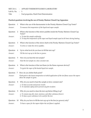
MET211-Lab-Practical questions -_lab_ex._2
- 1. 1 MET 211-L : APPLIED THERMODYNAMICS LABORATORY Lab Ex. No. : 1 Title : Fuel properties, Flash Point Determination Practical questions involving the use of Pensky Martens Closed Cup Apparatus: Question 1 What is the use of the thermometer in the Pensky Martens Closed Cup Tester? Answer: To measure the temperature of the liquid and vapor sample. Question 2 What is the function of the stirrer paddles inside the Pensky Martens Closed Cup Tester? Answer: a. To heat the sample uniformly. b. To keep the temperature of the vapor and liquid sample equal at all times during heating. Question 3 What is the function of the stirrer shaft in the Pensky Martens Closed Cup Tester? Answer: To drive or rotate the stirrer paddles. Question 4 Up to what level do you have to fill the test cup? Answer: Fill the test cup up to the line or groove. Question 5 How do you heat the test sample? Answer: Heat the test sample at a slow constant rate. Question 6 What is the function of the test flame (or the flame exposure device)? Answer: To ignite the vapor of the heated liquid test sample. Question 7 How do you define flash point? Answer: Flash point is the lowest temperature at which application of the test flame causes the vapors above the sample to ignite. Question 8 Why do you need to heat the sample at slow constant rate? Answer: a. To have accurate and precise results. b. To maintain safety and to prevent any fire incident. Question 9 Why do you need to clean the test cup before filling it up? Answer: a. To remove any dirt, dust, moisture, and other substance from it. b. To have a pure substance to be used for the test. Question 10 Why do you have to fill the test cup up to the line (or groove) only? Answer: To have a space for the vapors before the test flame is applied.
- 2. 2 Question 11 Why do you need to close the test cup? Answer: a. To keep the vapor above the sample. b. To prevent the vapor from escaping and mixing with the air outside. Question 12 What is the objective of this laboratory exercise? Answer: To determine the flash point of a certain petroleum sample. Question 13 What is the usefulness of flash point determination in the petrochemical industry? Answer: To determine the transportation and storage temperature requirements for lubricants. Question 14 What is the objective of the laboratory exercise? Answer: To determine the flash point of a certain petroleum product sample. Table of Components: No. Name of Item No. Name of Item 1 Flame exposure device (Test flame) 4 Stirrer paddle for vapor 2 Thermometer 5 Stirrer paddle for liquid 3 Stirrer shaft 6 Test Cup 1 2 4 3 5 6