Downloaded 360 times
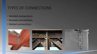
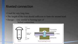
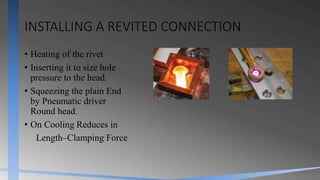
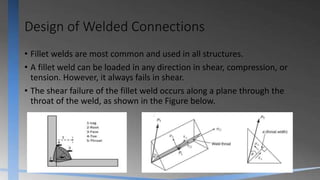
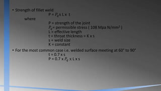


The document discusses various types of connections in steel structures including welded, riveted, and bolted connections, highlighting their design, advantages, and disadvantages. It elaborates on the methods of welding and riveting, including the design properties, strengths, and stress distributions of joints. Key formulas for determining the strength and dimensions of welds and rivets are provided, along with design procedures and recommendations for successful joint construction.


