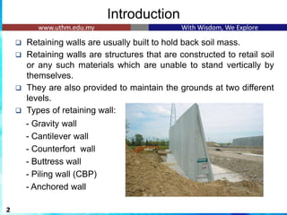
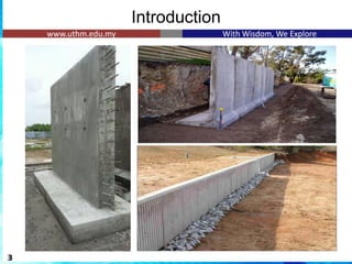
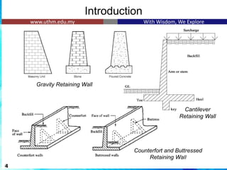
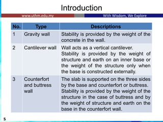
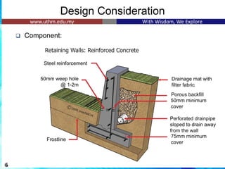
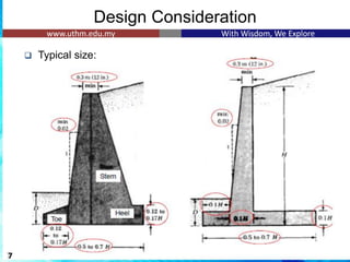
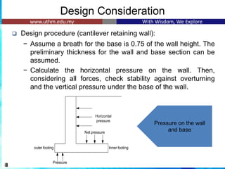
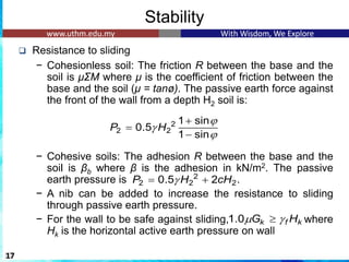
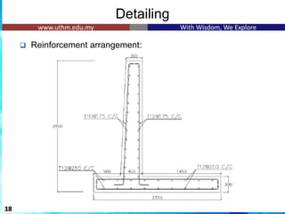
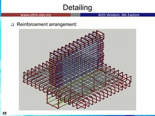
The document discusses the design of reinforced concrete retaining walls, which are used to hold back soil and maintain different ground levels. It details various types of retaining walls, design considerations, calculations for earth pressure, stability checks, and specific examples involving cantilever retaining walls. Additionally, it emphasizes the importance of factors such as surcharge loading, sliding resistance, and reinforcement arrangements in ensuring structural integrity.


![Example 5.2
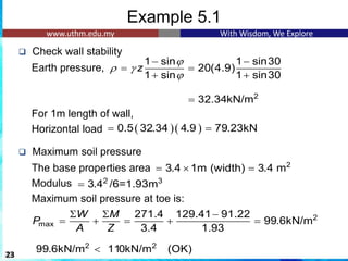
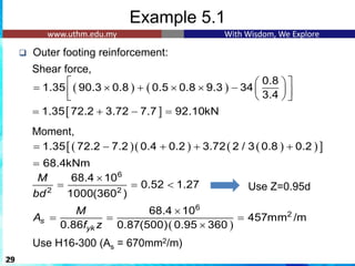
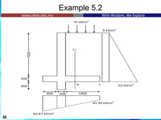
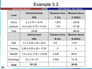
Maximum soil pressure at service load:
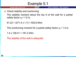
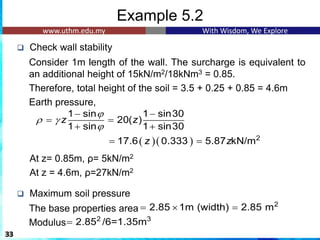
❑ Check stability and overturning
The stability moment about the toe A of the wall for a partial
safety factor γf = 0.9 is:
1
59.59 + [181.29 x (2.85/2)] = 317.9 x 0.9 = 286.11 kNm
1
The overturning moment for a partial safety factor γf = 1.1 is:
1
1.1 x 86.64 = 95.3 kNm 1
The stability of the wall is adequate
35
2 2
83.76kN/m 110kN/m (OK)
2
max
181.29 86.67 59.59
83.76kN/m
2.85 1.35
W M
P
A Z
−
= + = + =](https://image.slidesharecdn.com/chapter5-240804144430-30a99b7d/85/Retaining-wall-analysis-and-design-according-to-aci-35-320.jpg)