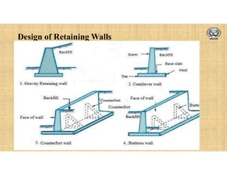
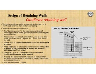
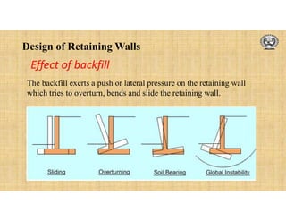
Design of Retaining Walls
Retaining walls are usually
built to hold back soil
mass. However, retaining
walls can also be constructed
for aesthetic landscaping
purposes.
Retaining wall is a structure
used for maintaining the
ground surfaces at different
elevations on either side of it.
What is a Retaining wall?
Design of Retaining Walls
What is the use of a Retaining wall?
Design of Retaining Walls
Components of a retaining wall
Batter
Drainage Hole
Toe
Design of Retaining Walls
•1. Gravity Retaining Walls /Semi-Gravity
Retaining Walls
•2. Cantilever Retaining Walls (L or T shape)
•3. Counter fort Retaining Walls
•4. Buttress Retaining wall
Types of retaining wall
Design of Retaining Walls
• The “gravity wall” provides stability by
virtue of its own weight , and therefore, is
rather massive in size.
• It is usually built in stone masonry, and
occasionally in plain concrete
 The thickness of wall is also governed by
need to eliminate or limit the resulting
tensile stress to its permissible limit .
 Plain concrete gravity walls are not used
for heights exceeding about 3m, for
obvious economic reasons.
 Stress developed is very low.
 These walls are so proportioned that no
tension is developed anywhere and the
resultant of forces remain within the
middle third of the base.
Gravity retaining wall
Design of Retaining Walls
Cantilever retaining wall
 Concrete cantilever wall is an example and consists of a
reinforced concrete stem and a base footing.
 These walls are non-proprietary.
 The “Cantilever wall ” is the most common type of
retaining structure and is generally economical for heights
up to about 8m.
 The structure consists of vertical stem , and a base slab,
made up of two distinct regions, viz., a heel slab and a
toe slab
 “Stem” acts as a vertical cantilever under the lateral earth
pressure
 “Heel slab” acts as a horizontal cantilever under the action
of weight of the retained earth (minus soil pressure
acting upwards from below)
 “Toe slab ” acts as a cantilever under the action of
resulting soil pressure acting upward.
 It resists the horizontal earth pressure as well as other
vertical pressure by way of bending of various components
acting as cantilevers.
 May be L shaped or T shaped.
Design of Retaining Walls
 Stem and Heel slab are strengthened by
providing counterforts at some suitable intervals.
 The stability of the wall is maintained essentially
by the weight of the earth on the heel slab plus
the self weight of the structure.
 Counterfort wall are placed at regular intervals of
about1/3 to ½ of the wall height, interconnecting
the stem with the heel slab
 The counterforts are concealed within the
retained earth on the rear side of the wall.
 This wall is economical for heights above
(approximately) 7m.
 The counterforts subdivide the vertical slab
(stem) into rectangular panels and support them
on two sides(suspender-style), and themselves
behave essentially as vertical cantilever beams of
T-section and varying depth.
Counterfort Retaining wall
Design of Retaining Walls
• Backfill
• The material retained is known as Backfill
• Surcharge
• The backfill above the level of the top of the wall
• Inclined surcharge
• The sloping backfill is termed as Inclined surcharge
• Earth Pressure
• The pressure on the wall due to backfill
Terminology
Design of Retaining Walls
Effect of backfill
The backfill exerts a push or lateral pressure on the retaining wall
which tries to overturn, bends and slide the retaining wall.
Design of Retaining Walls
Earth pressure is the pressure exerted by the
retaining material on the retaining wall. This
pressure tends to deflect the wall outward.
Types of earth pressure :
Earth pressure at rest
Active earth pressure or earth pressure (Pa)
and
Passive earth pressure (Pp).
Active earth pressure tends to deflect the wall
away from the backfill.
Earth Pressure
Pa
GL
Variation of Earth pressure
Design of Retaining Walls
Earth Pressure at rest
When the soil behind the wall is prevented from lateral
movement (towards or away from soil) of wall, the
pressure is known as earth pressure at rest.
This is the case when wall has a considerable rigidity.
Basement walls generally fall in this category.
Design of Retaining Walls
If a retaining wall is allowed to move away
from the soil accompanied by a lateral soil
expansion, the earth pressure decreases
with the increasing expansion.
A shear failure of the soil is resulted with
any further expansion and a sliding wedge
tends to move forward and downward.
The earth pressure associated with this
state of failure is the minimum pressure
and is known as active earth pressure.
Active Earth Pressure Passive Earth Pressure
If a retaining wall is allowed to move
towards the soil accompanied by a lateral
soil compression, the earth pressure
increase with the increasing compression
in the soil.
Design of Retaining Walls
Earth pressure depends on
• type of backfill
• the height of wall and
• the soil conditions
Soil conditions: The different soil conditions are
• Dry leveled back fill
• Moist leveled backfill
• Submerged leveled backfill
• Leveled backfill with uniform surcharge
• Backfill with sloping surface
Factors affecting Earth Pressure
Design of Retaining Walls
Computation of Bending Moment and Shear Force
Maximum pressure at any height, p=kah
Total pressure at any height from top,
pa=1/2[kah]h = [kah2]/2
Bending moment at any height
M=paxh/3= [kah3]/6
 Total pressure, Pa= [kaH2]/2
Total Bending moment at bottom,
M = [kaH3]/6
Pa
H
h
kaH
M
Design of Retaining Walls
Where, ka= Coefficient of active earth pressure
= (1-sin)/(1+sin)=tan2
= 1/kp, coefficient of passive earth pressure
= Angle of internal friction or angle of repose
=Unit weigh or density of backfill
If = 30, ka=1/3 and kp=3. Thus ka is 9 times kp
Design of Retaining Walls
Pressure due to inclined backfill
pa= ka H at the bottom and is
parallel to inclined surface of
backfill
ka=
Where =Angle of surcharge
 Total pressure at bottom
=Pa= ka H2/2


















 2
2
2
2
cos
cos
cos
cos
cos
cos
cos
Design of Retaining Walls
Design Requirements for Retaining wall
Following conditions must be satisfied for stability of wall (IS:456-2000).
• It should not overturn
• It should not slide
• It should not subside, i.e Max. pressure at the toe should not exceed the
safe bearing capacity of the soil under working condition
Design of Retaining Walls
Factor of safety against overturning
= MR / MO  1.55 (=1.4/0.9)
Where,
MR =Stabilising moment or restoring
moment
MO =overturning moment
As per IS:456-2000,
MR>1.2 MO, ch. DL + 1.4 MO, ch. IL
0.9 MR  1.4 MO, ch IL
Check against Overturning
Design of Retaining Walls
FOS against sliding
= Resisting force to sliding/
Horizontal force causing
sliding
= W/Pa  1.55 (=1.4/0.9)
As per IS:456:2000
1.4 = ( 0.9W)/Pa
Check against Sliding
Friction  W
SLIDING OF WALL
Design of Retaining Walls
=45 + /2
a
pp
R
A
B

W ka(H+a)
PA
H+a
H
C
In case the wall is unsafe against
sliding
pp= p tan2 (45 +/2)
= p kp
where pp= Unit passive pressure on
soil above shearing plane AB
p= Earth pressure at BC
R=Total passive resistance=ppxa
Design of Shear Key
Design of Retaining Walls
If W= Total vertical force acting at the key base
= shearing angle of passive resistance
R= Total passive force = pp x a
PA=Active horizontal pressure at key base for H+a
W=Total frictional force under flat base
For equilibrium, R + W =FOS x PA
FOS= (R + W)/ PA  1.55
Design of Shear Key …contd
Design of Retaining Walls
T
x1
x2
W1
W2
W3
W4
b/2
b/6
e
x
b
H/3
Pa
W
H
h
Pmax
Pmin.
R
Computation of pressure below toe
Design of Retaining Walls
Let the resultant R due to W and Pa
lie at a distance x from the toe.
X = M/W,
M = sum of all moments about toe.
Eccentricity of the load = e = (b/2-x)  b/6
Minimum pressure at heel= >Zero.
For zero pressure, e=b/6, resultant should cut the base within the
middle third.
Maximum pressure at toe=  SBC of soil.









b
e
b
W 6
1
Pmin









b
e
b
W 6
1
Pmax
Computation of pressure below toe …contd
Design of Retaining Walls
Depth of Foundation
Rankine’s formula:
Df =
=
2
sin
1
sin
1











SBC
2
a
k
γ
SBC
Df
Design of Retaining Walls
Stem: Top width 200 mm to 400 mm
Base slab width b= 0.4H to 0.6H, 0.6H
to 0.75H for surcharged wall
Base slab thickness= H/10 to H/14
Toe projection= (1/3-1/4) Base width
Preliminary proportioning of Cantilever Wall
H
200
b= 0.4H to 0.6H
tp= (1/3-1/4)b
H/10 –
H/14
Design of Retaining Walls
Behaviour or structural action and design of stem, heel and toe slabs are same as that
of any cantilever slab.
Structural action of Cantilever Retaining Wall
Design of Retaining Walls
Stem, toe and heel acts as cantilever slabs
Stem design: Mu=psf (ka  H3/6)
Determine the depth d from Mu = Mu, lim=Qbd2
Design as balanced section or URS and find steel
Mu=0.87 fy Ast[d-fyAst/(fckb)]
Design of Cantilever Retaining Wall
Design of Retaining Walls
Ast
Provided
Ast/2
Ast
Dist.
from
top
h2
Every
alternate
bar cut
Ast
Ast/2 h2
Ldt
h1c
h1
Effective depth (d) is
Proportional to h
Bending moment is
proportional to h3
Ast is αl to (BM/d) and is
αl to h2
Cross section Curtailment curve
2
2
2
1
2
1
.
.
h
h
A
A
e
i
st
st

Curtailment of Reinforcement
Design of Retaining Walls
1. Heel slab and toe slab should also be designed as cantilever.
For this stability analysis should be performed as explained
and determine the maximum bending moments at the
junction.
2. Determine the reinforcement.
3. Also check for shear at the junction.
4. Provide enough development length.
5. Provide the distribution steel
Design of heel and toe slab
Design of Retaining Walls
DRAINAGE OF THE BACK FILL
Design of Retaining Walls
Sand + Stone Filter
Weepers
Or
Weep Holes
Design of Retaining Walls
Drainage Pipes f 100-200 mm @ 2.5 to 4 m
Design of Retaining Walls
Perforated Pipe
Suited for short walls

Retainig wall.pdf

  • 1.
  • 2.
    Design of RetainingWalls Retaining walls are usually built to hold back soil mass. However, retaining walls can also be constructed for aesthetic landscaping purposes. Retaining wall is a structure used for maintaining the ground surfaces at different elevations on either side of it. What is a Retaining wall?
  • 3.
    Design of RetainingWalls What is the use of a Retaining wall?
  • 4.
  • 5.
  • 6.
  • 7.
    Design of RetainingWalls Components of a retaining wall Batter Drainage Hole Toe
  • 8.
    Design of RetainingWalls •1. Gravity Retaining Walls /Semi-Gravity Retaining Walls •2. Cantilever Retaining Walls (L or T shape) •3. Counter fort Retaining Walls •4. Buttress Retaining wall Types of retaining wall
  • 9.
  • 10.
    Design of RetainingWalls • The “gravity wall” provides stability by virtue of its own weight , and therefore, is rather massive in size. • It is usually built in stone masonry, and occasionally in plain concrete  The thickness of wall is also governed by need to eliminate or limit the resulting tensile stress to its permissible limit .  Plain concrete gravity walls are not used for heights exceeding about 3m, for obvious economic reasons.  Stress developed is very low.  These walls are so proportioned that no tension is developed anywhere and the resultant of forces remain within the middle third of the base. Gravity retaining wall
  • 11.
    Design of RetainingWalls Cantilever retaining wall  Concrete cantilever wall is an example and consists of a reinforced concrete stem and a base footing.  These walls are non-proprietary.  The “Cantilever wall ” is the most common type of retaining structure and is generally economical for heights up to about 8m.  The structure consists of vertical stem , and a base slab, made up of two distinct regions, viz., a heel slab and a toe slab  “Stem” acts as a vertical cantilever under the lateral earth pressure  “Heel slab” acts as a horizontal cantilever under the action of weight of the retained earth (minus soil pressure acting upwards from below)  “Toe slab ” acts as a cantilever under the action of resulting soil pressure acting upward.  It resists the horizontal earth pressure as well as other vertical pressure by way of bending of various components acting as cantilevers.  May be L shaped or T shaped.
  • 12.
    Design of RetainingWalls  Stem and Heel slab are strengthened by providing counterforts at some suitable intervals.  The stability of the wall is maintained essentially by the weight of the earth on the heel slab plus the self weight of the structure.  Counterfort wall are placed at regular intervals of about1/3 to ½ of the wall height, interconnecting the stem with the heel slab  The counterforts are concealed within the retained earth on the rear side of the wall.  This wall is economical for heights above (approximately) 7m.  The counterforts subdivide the vertical slab (stem) into rectangular panels and support them on two sides(suspender-style), and themselves behave essentially as vertical cantilever beams of T-section and varying depth. Counterfort Retaining wall
  • 13.
    Design of RetainingWalls • Backfill • The material retained is known as Backfill • Surcharge • The backfill above the level of the top of the wall • Inclined surcharge • The sloping backfill is termed as Inclined surcharge • Earth Pressure • The pressure on the wall due to backfill Terminology
  • 14.
    Design of RetainingWalls Effect of backfill The backfill exerts a push or lateral pressure on the retaining wall which tries to overturn, bends and slide the retaining wall.
  • 15.
    Design of RetainingWalls Earth pressure is the pressure exerted by the retaining material on the retaining wall. This pressure tends to deflect the wall outward. Types of earth pressure : Earth pressure at rest Active earth pressure or earth pressure (Pa) and Passive earth pressure (Pp). Active earth pressure tends to deflect the wall away from the backfill. Earth Pressure Pa GL Variation of Earth pressure
  • 16.
    Design of RetainingWalls Earth Pressure at rest When the soil behind the wall is prevented from lateral movement (towards or away from soil) of wall, the pressure is known as earth pressure at rest. This is the case when wall has a considerable rigidity. Basement walls generally fall in this category.
  • 17.
    Design of RetainingWalls If a retaining wall is allowed to move away from the soil accompanied by a lateral soil expansion, the earth pressure decreases with the increasing expansion. A shear failure of the soil is resulted with any further expansion and a sliding wedge tends to move forward and downward. The earth pressure associated with this state of failure is the minimum pressure and is known as active earth pressure. Active Earth Pressure Passive Earth Pressure If a retaining wall is allowed to move towards the soil accompanied by a lateral soil compression, the earth pressure increase with the increasing compression in the soil.
  • 18.
    Design of RetainingWalls Earth pressure depends on • type of backfill • the height of wall and • the soil conditions Soil conditions: The different soil conditions are • Dry leveled back fill • Moist leveled backfill • Submerged leveled backfill • Leveled backfill with uniform surcharge • Backfill with sloping surface Factors affecting Earth Pressure
  • 19.
    Design of RetainingWalls Computation of Bending Moment and Shear Force Maximum pressure at any height, p=kah Total pressure at any height from top, pa=1/2[kah]h = [kah2]/2 Bending moment at any height M=paxh/3= [kah3]/6  Total pressure, Pa= [kaH2]/2 Total Bending moment at bottom, M = [kaH3]/6 Pa H h kaH M
  • 20.
    Design of RetainingWalls Where, ka= Coefficient of active earth pressure = (1-sin)/(1+sin)=tan2 = 1/kp, coefficient of passive earth pressure = Angle of internal friction or angle of repose =Unit weigh or density of backfill If = 30, ka=1/3 and kp=3. Thus ka is 9 times kp
  • 21.
    Design of RetainingWalls Pressure due to inclined backfill pa= ka H at the bottom and is parallel to inclined surface of backfill ka= Where =Angle of surcharge  Total pressure at bottom =Pa= ka H2/2                    2 2 2 2 cos cos cos cos cos cos cos
  • 22.
    Design of RetainingWalls Design Requirements for Retaining wall Following conditions must be satisfied for stability of wall (IS:456-2000). • It should not overturn • It should not slide • It should not subside, i.e Max. pressure at the toe should not exceed the safe bearing capacity of the soil under working condition
  • 23.
    Design of RetainingWalls Factor of safety against overturning = MR / MO  1.55 (=1.4/0.9) Where, MR =Stabilising moment or restoring moment MO =overturning moment As per IS:456-2000, MR>1.2 MO, ch. DL + 1.4 MO, ch. IL 0.9 MR  1.4 MO, ch IL Check against Overturning
  • 24.
    Design of RetainingWalls FOS against sliding = Resisting force to sliding/ Horizontal force causing sliding = W/Pa  1.55 (=1.4/0.9) As per IS:456:2000 1.4 = ( 0.9W)/Pa Check against Sliding Friction  W SLIDING OF WALL
  • 25.
    Design of RetainingWalls =45 + /2 a pp R A B  W ka(H+a) PA H+a H C In case the wall is unsafe against sliding pp= p tan2 (45 +/2) = p kp where pp= Unit passive pressure on soil above shearing plane AB p= Earth pressure at BC R=Total passive resistance=ppxa Design of Shear Key
  • 26.
    Design of RetainingWalls If W= Total vertical force acting at the key base = shearing angle of passive resistance R= Total passive force = pp x a PA=Active horizontal pressure at key base for H+a W=Total frictional force under flat base For equilibrium, R + W =FOS x PA FOS= (R + W)/ PA  1.55 Design of Shear Key …contd
  • 27.
    Design of RetainingWalls T x1 x2 W1 W2 W3 W4 b/2 b/6 e x b H/3 Pa W H h Pmax Pmin. R Computation of pressure below toe
  • 28.
    Design of RetainingWalls Let the resultant R due to W and Pa lie at a distance x from the toe. X = M/W, M = sum of all moments about toe. Eccentricity of the load = e = (b/2-x)  b/6 Minimum pressure at heel= >Zero. For zero pressure, e=b/6, resultant should cut the base within the middle third. Maximum pressure at toe=  SBC of soil.          b e b W 6 1 Pmin          b e b W 6 1 Pmax Computation of pressure below toe …contd
  • 29.
    Design of RetainingWalls Depth of Foundation Rankine’s formula: Df = = 2 sin 1 sin 1            SBC 2 a k γ SBC Df
  • 30.
    Design of RetainingWalls Stem: Top width 200 mm to 400 mm Base slab width b= 0.4H to 0.6H, 0.6H to 0.75H for surcharged wall Base slab thickness= H/10 to H/14 Toe projection= (1/3-1/4) Base width Preliminary proportioning of Cantilever Wall H 200 b= 0.4H to 0.6H tp= (1/3-1/4)b H/10 – H/14
  • 31.
    Design of RetainingWalls Behaviour or structural action and design of stem, heel and toe slabs are same as that of any cantilever slab. Structural action of Cantilever Retaining Wall
  • 32.
    Design of RetainingWalls Stem, toe and heel acts as cantilever slabs Stem design: Mu=psf (ka  H3/6) Determine the depth d from Mu = Mu, lim=Qbd2 Design as balanced section or URS and find steel Mu=0.87 fy Ast[d-fyAst/(fckb)] Design of Cantilever Retaining Wall
  • 33.
    Design of RetainingWalls Ast Provided Ast/2 Ast Dist. from top h2 Every alternate bar cut Ast Ast/2 h2 Ldt h1c h1 Effective depth (d) is Proportional to h Bending moment is proportional to h3 Ast is αl to (BM/d) and is αl to h2 Cross section Curtailment curve 2 2 2 1 2 1 . . h h A A e i st st  Curtailment of Reinforcement
  • 34.
    Design of RetainingWalls 1. Heel slab and toe slab should also be designed as cantilever. For this stability analysis should be performed as explained and determine the maximum bending moments at the junction. 2. Determine the reinforcement. 3. Also check for shear at the junction. 4. Provide enough development length. 5. Provide the distribution steel Design of heel and toe slab
  • 35.
    Design of RetainingWalls DRAINAGE OF THE BACK FILL
  • 36.
    Design of RetainingWalls Sand + Stone Filter Weepers Or Weep Holes
  • 37.
    Design of RetainingWalls Drainage Pipes f 100-200 mm @ 2.5 to 4 m
  • 38.
    Design of RetainingWalls Perforated Pipe Suited for short walls