Download to read offline


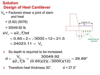
![Design of Heel Cantilever
Wu = (1.7) (120) (8) + (1.4) [18 x 120 + 2 x 150 ]
= 5076 lb/ft
ft
.
lb
76
.
88947
92
.
5
76
.
5
2
1
2
W
M
2
u
2
Vu = Factored shear a joint of stem and heel
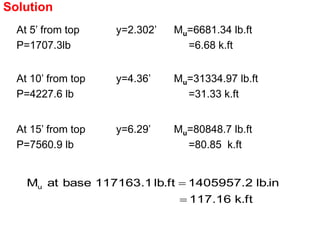
Solution
When the support reaction introduces compression into
the end region, then critical shear is at a distance d
from face of support. However, the support is not
producing compression, therefore, critical shear is at
joint of stem and heel.](https://image.slidesharecdn.com/retainingwalluol-230622091446-45876481/85/Retaining_Wall_UOL-pptx-43-320.jpg)
![Now Wu=(1.7)(120)(8)+(1.4)[(17.5)(120)+(2.5)(150)] = 5097 lb/ft
.
ft
.
lb
75
.
89315
)
92
.
5
)(
5097
(
2
1
M 2
u
005
.
0
f
200
00337
.
0
f
mR
2
1
1
m
1
psi
23
.
131
)
5
.
27
)(
12
)(
9
.
0
(
12
89315
bd
M
R
quired
Re
y
min
y
n
u
n 2
2
Solution
Design of Heel Cantilever](https://image.slidesharecdn.com/retainingwalluol-230622091446-45876481/85/Retaining_Wall_UOL-pptx-45-320.jpg)


Retaining walls are used to hold back earth or loose materials where natural slopes cannot form due to space restrictions. There are several types of retaining walls including gravity, cantilever, counterfort, and buttress walls. Stability requirements for retaining walls include ensuring individual parts can resist forces, and the wall as a whole is stable against settlement, sliding, and overturning. Proper drainage is also important to consider in retaining wall design.


