Downloaded 126 times


![Computation of Traffic for Use of Pavement Thickness
Design Chart
365 x A[(1+r)n – 1]
N = --------------------------- x D x F
r
N = Cumulative No. of standard axles to be catered for the design in
terms of msa
D = Lane distribution factor
A = Initial traffic, in the year of completion of construction, in terms
of number of commercial vehicles per day
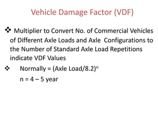
F = Vehicle Damage Factor
n = Design life in years
r = Annual growth rate of commercial vehicles](https://image.slidesharecdn.com/pavement-181204143721/85/Pavement-28-320.jpg)


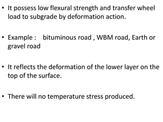
This document discusses different types of pavements and factors considered in pavement design. It describes flexible and rigid pavements, and notes that pavement refers to the top road surface layer, including sub-base and base layers below. The objectives of pavement are to transfer wheel loads, prevent water entry into subgrades, and provide a smooth surface. Factors in design include traffic load, subgrade soil, design life, climate, materials, drainage, and geometry. The CBR test method is explained for evaluating subgrade strength.