Downloaded 141 times
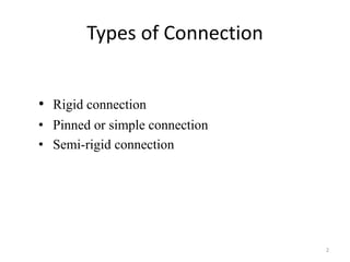
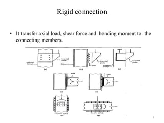
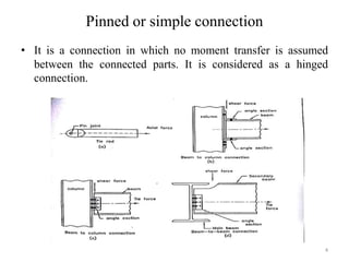
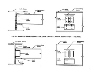
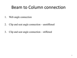
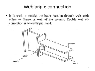
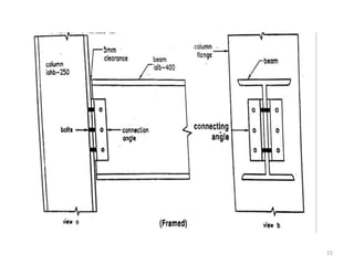
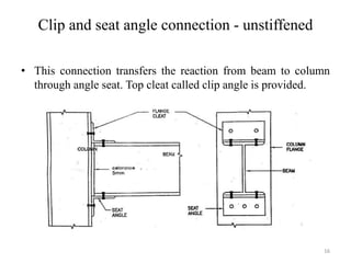
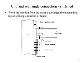
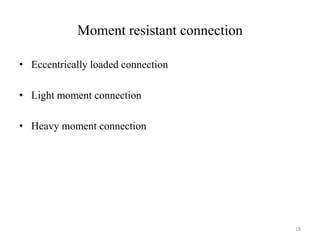
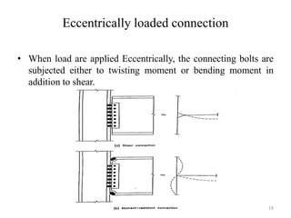


This document discusses various types of beam and column connections used in steel structures. It describes rigid, pinned, and semi-rigid connections. It also discusses different beam to beam connections like web cleat angle, clip and seat angle, and web and seat angle connections. Beam to column connections including web angle, clip and seat angle stiffened and unstiffened are explained. Finally, it covers moment resistant connections like eccentrically loaded, light moment and heavy moment connections and provides examples of designing some typical connections.


