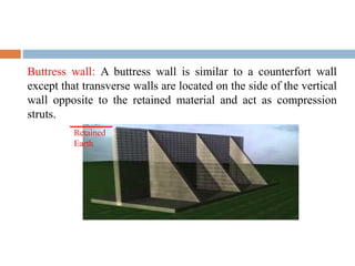
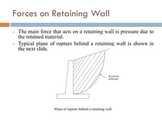
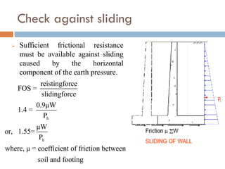
SlideShare a Scribd company logo
1 of 53
Download to read offline
RETAINING WALL
Dr. Hassan Irtaza, Professor
Department of Civil Engineering, A.M.U., Aligarh – 202002, India
Retaining Wall
Retaining wall is a structure used to retain earth or other
loose materials which would not be able to withstand
vertically by itself. In other words a retaining wall is a
structure designed and constructed to resist the lateral
pressure of soil when there is a desired change in ground
elevation that exceeds the angle of repose of the soil.
The retained materials exert pressure or push on the
structure and this tends to overturn and slide it.
The weight of the retaining wall is of considerable
significance in achieving and maintaining stability of the
entire system.
Conventional Retaining Walls
 Gravity Retaining Structures
 It may be of plain concrete or masonry
 Stability depends upon the self weight of the wall.
 Not economical for the design
Semi-gravity Retaining Structures
 It is of standard concrete.
Minimum amount of
reinforcement may be
used in the wall to reduce
the size of the wall.
 Not economical for the
design
Semi-gravity retaining wall
Cantilever Retaining Wall
 Reinforced concrete is
used in wall design with
thin stem and slab base.
 Each of the three
components acts a
cantilever beam.
 Stability is provided by
weight of the earth on the
base and weight of the
retaining wall.
 Relatively economical for
design.
Cantilever retaining wall
Counterfort/buttressed Retaining Walls
Similar to cantilever retaining walls, but thin slab stems
may be used at some interval to tie the base slab and stem in
order to reduce the shear force and bending moment for
more economical design.
(a) Counterfort wall (b) Buttressed wall
Counterfort: Counterforts are transverse walls spaced at certain
intervals and act as tension ties to support the vertical wall.
Stability is provided by weight of the earth on the base slab and
weight of the retaining wall.
Buttress wall: A buttress wall is similar to a counterfort wall
except that transverse walls are located on the side of the vertical
wall opposite to the retained material and act as compression
struts.
Retained
Earth
 A buttress is a compression member is more economical
than the tension counterfort, still the latter is more widely
used than a buttress because the counterfort is hidden
beneath the retained material. Moreover, buttress
occupies more space in front of the wall which otherwise
could be utilized more efficiently
Bridge Abutment
A wall type bridge abutment acts similar to a cantilever
retaining wall except that the bridge deck provides
additional horizontal restraint at top of the vertical slab.
This type of abutment is designed as a beam fixed at the
bottom and simply supported or partially restrained at the
top.
Bridge abutment Bridge abutment with piles bankseats
Box Culvert
A box culvert is a box like structure having either single cell
or multiple cells. It acts as a closed rigid frame that not only
resists lateral earth pressure but also vertical load from soil
above it or from both soil and highway vehicles.
Reinforced Earth Wall
Construction of a Reinforced Earth wall is straightforward and simple. Merely
place a layer of facing panels, bolt on the reinforcing strips then backfill and
compact. Repeat this cycle until the appropriate wall height has been reached.
Properly compacted to a uniformly high density, the earth combines with the
reinforcement to produce a strong, durable structure with predictable
performance characteristics.
Basic Components of Retaining Structures
 Facing unit – not necessary but usually used to maintain
appearance and avoid soil erosion between the reinforces.
 Reinforcement – strips or rods of metal, strips or sheets
of geotextiles, wire grids, or chain link fence or geogrids
fastened to the facing unit and extending into the backfill
some distance.
 The earth fill – usually select granular material with 15%
passing the 200 No. sieve.
Temporary retaining structures during excavation
Sheet Pile Wall
Gabion Wall
Counterfort Wall
Crib Wall
 Another type of gravity retaining structure
 It consists of precast concrete members linked together to
form a crib
 The zone between the member is filled with compacted soil
Retaining Wall Design: Proportioning
Firstly the approximate
dimensions are chosen
for the retaining wall.
Stability of the wall is
checked with these
dimensions.
Section is changed if it
is undesirable from the
stability or economy
point of view.
Retaining Wall Design: Proportioning
Forces on Retaining Wall
 The main force that acts on a retaining wall is pressure due to
the retained material.
 Typical plane of rupture behind a retaining wall is shown in
the next slide.
Plane of rupture behind a retaining wall
 The earth pressure try to overturn and slide a retaining wall.
 The magnitude and direction of the earth pressure can be
determined by applying the principles of soil mechanics.
 The pressure exerted by the retained material is
proportional to its density and to the distance below the
earth surface.
Design Considerations
In order to calculate the pressure exerted at any point on
the wall, the following must be taken in account:
 height of water table
 nature & type of soil
 subsoil water movements
 type of wall
 materials used in the construction of wall
The following two forms of earth pressure need to be
considered during the process of designing a retaining wall :
(a) Active Earth Pressure
“It is the pressure that at all times are tending to move or
overturn the retaining wall”
(b) Passive Earth Pressure
“It is reactionary pressures that will react in the form of a
resistance to movement of the wall.
Active Earth Pressure
It is composed of the earth wedge being retained together
with any hydrostatic pressure caused by the presence of
ground water. This pressure can be reduced by:
(i) The use of subsoil drainage behind the wall
(ii) Inserting drainage openings called weep holes through
the thickness of the stem to enable the water to drain
away.
Earth pressure behind a retaining wall is generally
calculated by Rankine’s theory for homogeneous
incompressible cohesionless soil assuming a hydrostatic
pressure distribution along the depth.
a a
2 2
2 2
p = C γ h
where, p = Active earth pressur
C coefficient of active earth pressure
cos cos cos
= cos
cos cos cos
= density of the retained materi
a
a
  

  


 
 
 
 
 
 
al
h = depth of the section below the earth surface
= angle of surcharge
= angle of repose of soil


If there is no surcharge, i.e. δ = 0, the pressure Pa acts parallel
to the top surface of the material retained, the coefficient of
active earth pressure becomes
The total force behind the wall is given by the area of the
pressure triangle, that is
per unit length of the wall and acts at a depth of 2/3 H below
the top.
a
1-sin
C =
1+sin


2
a a
1
P = C γ H
2
h a
v a
P = P cosδ
P = P sinδ
Passive Earth Pressure
 This pressure build up in front of the toe to resist the
movement of the wall if it tries to move forward.
 This pressure can be increased by enlarging the depth of
the toe or by forming a rib on the underside of the base.
 Rankine’s equation for passive pressure is given as:
2
p p
p
2 2
2 2
1
P = C γ H
2
where C = Coefficient of passive earth pressure
cosδ + cos δ - cos f
=cosδ
cosδ - cos δ - cos f
 
 
 
 
Some important points
 The passive earth pressure (more in error) is quite high as
compared with active earth pressure. Its contribution in
the design of retaining wall is neglected which is on the
conservative side.
 Retaining walls are seldom designed to retain saturated
earth fill, hence proper drainage must be ensured.
 Many times vehicles may travel over the retained
material near the wall and cause the dynamic static
pressures. The IRC and the IR Bridge rules prescribe an
equivalent static surcharge for road and railway vehicles.
 Equivalent static surcharge is also added in case the
building is constructed near the top of the retaining wall.
Stability Requirements of RW
The designed retaining wall must be able to ensure the
following (IS:456-2000) :
 Overturning doesn’t occur
 Sliding doesn’t occur
 The soil on which the wall rests mustn’t be overloaded,
i.e. the base width must be adequate to distribute the
load to the foundation soil without exceeding its bearing
capacity.
Check against overturning
 Clause 20.1 of IS 456 requires that the resisting moment is
not less than the sum of 1.2 times the maximum
overturning moment due to characteristic dead load and 1.4
times the maximum overturning moment due to
characteristic imposed loads. If the dead load provides the
restoring moment, only 0.9 times the characteristic dead
load should be considered. It further requires that restoring
moment due to imposed loads should not be considered.
 The factor of safety against overturning may be computed
by neglecting the contribution of vertical component of the
active earth pressure. If W is the sum of the vertical loads
made up of weight of backfill on the inner slab plus weight
of the wall and base slab plus weight of the front fill, if
used, the factor of safety is given as follows:
FS =
resisting moment
overturning moment
 
 
1
h
1
h
1
h
0.9Wx
1=
1.4P H 3
Wx
or, 1.55=
P H 3
where, x = centre of gravity of vertical loads from toe
H = depth of bottom of base below the earth surface
P = horizontal component of earth pressure
Check against sliding
 Sufficient frictional resistance
must be available against sliding
caused by the horizontal
component of the earth pressure.
h
h
reistingforce
FOS =
slidingforce
0.9μW
1.4 =
P
μW
or, 1.55=
P
where, μ = coefficient of friction between
soil and footing
Coefficient of friction between soil and concrete
 Base width must be adequate to distribute the load to the
foundation soil without exceeding its bearing capacity.
SOIL µ
Coarse grained soil (no silt) 0.55
Coarse grained soil (with silt) 0.45
Silt 0.35
Sound rock (rough surface) 0.60
Shear Keys
 The sliding resistance of retaining walls is derived from the
base friction between the wall base and the foundation
soils. To increase the sliding resistance of retaining walls,
other than providing a large self-weight or a large retained
soil mass, shear keys are to be installed at the wall base.
The principle of shear keys is as follows:
 The main purpose of installation of shear keys is to increase
the extra passive resistance developed by the height of
shear keys. However, active pressure developed by shear
keys also increases simultaneously. The success of shear
keys lies in the fact that the increase of passive pressure
exceeds the increase in active pressure, resulting in a net
improvement of sliding resistance.
In case wall is unsafe against
sliding
 
2
p p
p
p
P = p tan 45+ 2 = p k
where, P = unit passive pressure on soil
above shearing plane AB
p = Earth pressure at BC
R = Total passive resistance = P × a

Design of shear key – contd..
p
a
If W = total vertical force acting at the key base¨
Ø = shearing angle of passive resistance
R = total passive force = P × a
P = active horizontal pressure at key base for H+a
μ W

 
A
A
= totalfrictionalforceunderflatbase
for equilibrium, R + μ W = FOS × P
FOS = R+μ W P 1.55




Maximum pressure at the toe
 
a
min
Let the resultant R due to W and P lie at a distance x from the toe
x = M W,
M = sum of all moments about toe
b b
eccentricity of the load = e = -x <
2 6
W 6e
Minimum pressure at heel = P = 1- >
b b
 
 
 

 


max
zero
for zero pressure, e = b 6, resultant should cut the base within the middle third
W 6e
Maximum pressure at toe = P = 1+
b b
< Safe Bearin
 
 
 

g Capacity of soil
Depth of Foundation
Rankine’s Formula
2
2
1 sin
1 sin
f
a
SBC
D
SBC
k

 

 

  

 

Preliminary Proportioning
T Shaped wall
Stem top width 200 mm to 400 mm
Base slab width b = 0.4H to 0.6H
= 0.75 H for surcharged wall
Base slab thickness = H/10 to H/14
Toe Projection = 1/3 to 1/4 of Base width
Structural Behavior of Retaining Wall
Design of Stem, heel
and toe slabs are same
as that of any cantilever slab.
Stem design
 Stem design
3
u a
2
u u,lim
y st
u ck st
ck
M = k γH /6
Determine the depth d from M = M = Qbd
Design as balanced section
or underreinforced and find steel
σ A
M =0.87σ A d-
σ b
Check for shear at the junction
Provide enough developmen
 
 
 
t length
Provide distribution steel
Curtailment of bars
Analysis of Counterfort Retaining Wall
 When H exceeds about 6 m
 Stem and heel thickness is more
 When more bending is acting at the
stem base, more steel will be required,
hence, Cantilever - T type retaining
wall is Uneconomical
 Counterforts - Trapezoidal section is
provided at spacing of 1.5 m - 3 m c/c
Parts of CRW
Same as that of the Cantilever Retaining Wall plus Counterfort
Design of Stem
 The stem acts as a continuous slab.
 Soil pressure acts as the load on the
slab.
 Earth pressure varies linearly over
height.
 The slab deflects away from the earth
face between the counterforts.
 The bending moment in the stem is
maximum at the base and reduces
towards top.
 But the thickness of the wall is kept
constant and only the area of steel is
reduced.
Maximum Bending Moments for Stem
 Maximum +ve B.M. = pl2/16 (occuring
mid-way between counterforts)
 and Maximum -ve B.M. =
pl2/12(occuring at inner face of
counterforts)
 where, l is the clear distance between
counterforts and p is the intensity of
soil pressure
Design of Toe Slab
 The base width = b = 0.6 H to 0.7 H
 The projection = 1/3 to 1/4 of base
width.
 The toe slab is subjected to an upward
soil reaction and is designed as cantilever
slab fixed at the front face of the stem.
 Reinforcement is provided on earth face
along the length of the toe slab.
 In case the toe slab projection is large i.e.
> b/3, front counterforts are provided
above the toe slab and the slab is
designed as continuous horizontal slab
spanning between the front counterforts.
Design of Heel Slab
 The heel slab is designed as a
continuous slab spanning over the
counterforts and is subjected to
downward forces due to weight of
soil plus self weight of slab and an
upward force due to soil reaction.
 Maximum +ve B.M. = pl2/16
(midway between counterforts)
 Maximum negative B.M. = pl2/12
(occuring at counterforts)
Design of Counterforts
 The counterforts are subjected to
outward reaction from the stem.
 This produces tension along the outer
sloping face of the counterforts.
 The innerface supporting the stem is in
compression. Thus counterforts are
designed as a T-beam of varying depth.
 The main steel provided along the
sloping face shall be anchored properly
at both ends.
 The depth of the counterfort is measured
perpendicular to the sloping side.
Behaviour of Counterfort Retaining Wall
Important Points
 Loads on Wall
 Deflected shape
 Nature of BMs
 Position of steel
 Counterfort details
THANKS

More Related Content

Similar to retaining walls ALIG.pdf

Similar to retaining walls ALIG.pdf (20)

Retaining walls
Retaining walls Retaining walls
Retaining walls
 
Retainig wall.pdf
Retainig wall.pdfRetainig wall.pdf
Retainig wall.pdf
 
Lateral earth pressure Theories Design of retaining.pptx
Lateral earth pressure Theories   Design of retaining.pptxLateral earth pressure Theories   Design of retaining.pptx
Lateral earth pressure Theories Design of retaining.pptx
 
Lateral earth pressure Theories & Design of retaining.pptx
Lateral earth pressure Theories &  Design of retaining.pptxLateral earth pressure Theories &  Design of retaining.pptx
Lateral earth pressure Theories & Design of retaining.pptx
 
sa-11 Unit i
sa-11 Unit isa-11 Unit i
sa-11 Unit i
 
Ch8 retaining-walls
Ch8 retaining-wallsCh8 retaining-walls
Ch8 retaining-walls
 
Foundation (2)
Foundation (2)Foundation (2)
Foundation (2)
 
Gabion walls design guide
Gabion walls design guideGabion walls design guide
Gabion walls design guide
 
RETAINING WALL
RETAINING WALLRETAINING WALL
RETAINING WALL
 
Retaining wall
Retaining wallRetaining wall
Retaining wall
 
Retaining wall ppt Final year Civil ENGINEERING
Retaining wall ppt Final year Civil ENGINEERINGRetaining wall ppt Final year Civil ENGINEERING
Retaining wall ppt Final year Civil ENGINEERING
 
Retaining wall
Retaining wallRetaining wall
Retaining wall
 
Theory of structures
Theory of structuresTheory of structures
Theory of structures
 
Analysis and design of reinforced concrete stepped cantilever retaining wall
Analysis and design of reinforced concrete stepped cantilever retaining wallAnalysis and design of reinforced concrete stepped cantilever retaining wall
Analysis and design of reinforced concrete stepped cantilever retaining wall
 
footing
footingfooting
footing
 
earthquake resistant masonry buildings
 earthquake resistant masonry buildings earthquake resistant masonry buildings
earthquake resistant masonry buildings
 
Differnt types of Retaining walls
Differnt types of Retaining wallsDiffernt types of Retaining walls
Differnt types of Retaining walls
 
Foundation
Foundation Foundation
Foundation
 
Retaining walls
Retaining wallsRetaining walls
Retaining walls
 
Foundation
FoundationFoundation
Foundation
 

Recently uploaded

(ANJALI) Dange Chowk Call Girls Just Call 7001035870 [ Cash on Delivery ] Pun...
(ANJALI) Dange Chowk Call Girls Just Call 7001035870 [ Cash on Delivery ] Pun...(ANJALI) Dange Chowk Call Girls Just Call 7001035870 [ Cash on Delivery ] Pun...
(ANJALI) Dange Chowk Call Girls Just Call 7001035870 [ Cash on Delivery ] Pun...ranjana rawat
 
Analog to Digital and Digital to Analog Converter
Analog to Digital and Digital to Analog ConverterAnalog to Digital and Digital to Analog Converter
Analog to Digital and Digital to Analog ConverterAbhinavSharma374939
 
VIP Call Girls Service Hitech City Hyderabad Call +91-8250192130
VIP Call Girls Service Hitech City Hyderabad Call +91-8250192130VIP Call Girls Service Hitech City Hyderabad Call +91-8250192130
VIP Call Girls Service Hitech City Hyderabad Call +91-8250192130Suhani Kapoor
 
Porous Ceramics seminar and technical writing
Porous Ceramics seminar and technical writingPorous Ceramics seminar and technical writing
Porous Ceramics seminar and technical writingrakeshbaidya232001
 
Introduction to IEEE STANDARDS and its different types.pptx
Introduction to IEEE STANDARDS and its different types.pptxIntroduction to IEEE STANDARDS and its different types.pptx
Introduction to IEEE STANDARDS and its different types.pptxupamatechverse
 
IMPLICATIONS OF THE ABOVE HOLISTIC UNDERSTANDING OF HARMONY ON PROFESSIONAL E...
IMPLICATIONS OF THE ABOVE HOLISTIC UNDERSTANDING OF HARMONY ON PROFESSIONAL E...IMPLICATIONS OF THE ABOVE HOLISTIC UNDERSTANDING OF HARMONY ON PROFESSIONAL E...
IMPLICATIONS OF THE ABOVE HOLISTIC UNDERSTANDING OF HARMONY ON PROFESSIONAL E...RajaP95
 
(PRIYA) Rajgurunagar Call Girls Just Call 7001035870 [ Cash on Delivery ] Pun...
(PRIYA) Rajgurunagar Call Girls Just Call 7001035870 [ Cash on Delivery ] Pun...(PRIYA) Rajgurunagar Call Girls Just Call 7001035870 [ Cash on Delivery ] Pun...
(PRIYA) Rajgurunagar Call Girls Just Call 7001035870 [ Cash on Delivery ] Pun...ranjana rawat
 
VIP Call Girls Service Kondapur Hyderabad Call +91-8250192130
VIP Call Girls Service Kondapur Hyderabad Call +91-8250192130VIP Call Girls Service Kondapur Hyderabad Call +91-8250192130
VIP Call Girls Service Kondapur Hyderabad Call +91-8250192130Suhani Kapoor
 
SPICE PARK APR2024 ( 6,793 SPICE Models )
SPICE PARK APR2024 ( 6,793 SPICE Models )SPICE PARK APR2024 ( 6,793 SPICE Models )
SPICE PARK APR2024 ( 6,793 SPICE Models )Tsuyoshi Horigome
 
Introduction and different types of Ethernet.pptx
Introduction and different types of Ethernet.pptxIntroduction and different types of Ethernet.pptx
Introduction and different types of Ethernet.pptxupamatechverse
 
What are the advantages and disadvantages of membrane structures.pptx
What are the advantages and disadvantages of membrane structures.pptxWhat are the advantages and disadvantages of membrane structures.pptx
What are the advantages and disadvantages of membrane structures.pptxwendy cai
 
Structural Analysis and Design of Foundations: A Comprehensive Handbook for S...
Structural Analysis and Design of Foundations: A Comprehensive Handbook for S...Structural Analysis and Design of Foundations: A Comprehensive Handbook for S...
Structural Analysis and Design of Foundations: A Comprehensive Handbook for S...Dr.Costas Sachpazis
 
Decoding Kotlin - Your guide to solving the mysterious in Kotlin.pptx
Decoding Kotlin - Your guide to solving the mysterious in Kotlin.pptxDecoding Kotlin - Your guide to solving the mysterious in Kotlin.pptx
Decoding Kotlin - Your guide to solving the mysterious in Kotlin.pptxJoão Esperancinha
 
Software Development Life Cycle By Team Orange (Dept. of Pharmacy)
Software Development Life Cycle By  Team Orange (Dept. of Pharmacy)Software Development Life Cycle By  Team Orange (Dept. of Pharmacy)
Software Development Life Cycle By Team Orange (Dept. of Pharmacy)Suman Mia
 
High Profile Call Girls Nashik Megha 7001305949 Independent Escort Service Na...
High Profile Call Girls Nashik Megha 7001305949 Independent Escort Service Na...High Profile Call Girls Nashik Megha 7001305949 Independent Escort Service Na...
High Profile Call Girls Nashik Megha 7001305949 Independent Escort Service Na...Call Girls in Nagpur High Profile
 
APPLICATIONS-AC/DC DRIVES-OPERATING CHARACTERISTICS
APPLICATIONS-AC/DC DRIVES-OPERATING CHARACTERISTICSAPPLICATIONS-AC/DC DRIVES-OPERATING CHARACTERISTICS
APPLICATIONS-AC/DC DRIVES-OPERATING CHARACTERISTICSKurinjimalarL3
 
(RIA) Call Girls Bhosari ( 7001035870 ) HI-Fi Pune Escorts Service
(RIA) Call Girls Bhosari ( 7001035870 ) HI-Fi Pune Escorts Service(RIA) Call Girls Bhosari ( 7001035870 ) HI-Fi Pune Escorts Service
(RIA) Call Girls Bhosari ( 7001035870 ) HI-Fi Pune Escorts Serviceranjana rawat
 
Introduction to Multiple Access Protocol.pptx
Introduction to Multiple Access Protocol.pptxIntroduction to Multiple Access Protocol.pptx
Introduction to Multiple Access Protocol.pptxupamatechverse
 
Internship report on mechanical engineering
Internship report on mechanical engineeringInternship report on mechanical engineering
Internship report on mechanical engineeringmalavadedarshan25
 

Recently uploaded (20)

(ANJALI) Dange Chowk Call Girls Just Call 7001035870 [ Cash on Delivery ] Pun...
(ANJALI) Dange Chowk Call Girls Just Call 7001035870 [ Cash on Delivery ] Pun...(ANJALI) Dange Chowk Call Girls Just Call 7001035870 [ Cash on Delivery ] Pun...
(ANJALI) Dange Chowk Call Girls Just Call 7001035870 [ Cash on Delivery ] Pun...
 
Analog to Digital and Digital to Analog Converter
Analog to Digital and Digital to Analog ConverterAnalog to Digital and Digital to Analog Converter
Analog to Digital and Digital to Analog Converter
 
VIP Call Girls Service Hitech City Hyderabad Call +91-8250192130
VIP Call Girls Service Hitech City Hyderabad Call +91-8250192130VIP Call Girls Service Hitech City Hyderabad Call +91-8250192130
VIP Call Girls Service Hitech City Hyderabad Call +91-8250192130
 
Porous Ceramics seminar and technical writing
Porous Ceramics seminar and technical writingPorous Ceramics seminar and technical writing
Porous Ceramics seminar and technical writing
 
Introduction to IEEE STANDARDS and its different types.pptx
Introduction to IEEE STANDARDS and its different types.pptxIntroduction to IEEE STANDARDS and its different types.pptx
Introduction to IEEE STANDARDS and its different types.pptx
 
IMPLICATIONS OF THE ABOVE HOLISTIC UNDERSTANDING OF HARMONY ON PROFESSIONAL E...
IMPLICATIONS OF THE ABOVE HOLISTIC UNDERSTANDING OF HARMONY ON PROFESSIONAL E...IMPLICATIONS OF THE ABOVE HOLISTIC UNDERSTANDING OF HARMONY ON PROFESSIONAL E...
IMPLICATIONS OF THE ABOVE HOLISTIC UNDERSTANDING OF HARMONY ON PROFESSIONAL E...
 
(PRIYA) Rajgurunagar Call Girls Just Call 7001035870 [ Cash on Delivery ] Pun...
(PRIYA) Rajgurunagar Call Girls Just Call 7001035870 [ Cash on Delivery ] Pun...(PRIYA) Rajgurunagar Call Girls Just Call 7001035870 [ Cash on Delivery ] Pun...
(PRIYA) Rajgurunagar Call Girls Just Call 7001035870 [ Cash on Delivery ] Pun...
 
VIP Call Girls Service Kondapur Hyderabad Call +91-8250192130
VIP Call Girls Service Kondapur Hyderabad Call +91-8250192130VIP Call Girls Service Kondapur Hyderabad Call +91-8250192130
VIP Call Girls Service Kondapur Hyderabad Call +91-8250192130
 
SPICE PARK APR2024 ( 6,793 SPICE Models )
SPICE PARK APR2024 ( 6,793 SPICE Models )SPICE PARK APR2024 ( 6,793 SPICE Models )
SPICE PARK APR2024 ( 6,793 SPICE Models )
 
Introduction and different types of Ethernet.pptx
Introduction and different types of Ethernet.pptxIntroduction and different types of Ethernet.pptx
Introduction and different types of Ethernet.pptx
 
What are the advantages and disadvantages of membrane structures.pptx
What are the advantages and disadvantages of membrane structures.pptxWhat are the advantages and disadvantages of membrane structures.pptx
What are the advantages and disadvantages of membrane structures.pptx
 
Structural Analysis and Design of Foundations: A Comprehensive Handbook for S...
Structural Analysis and Design of Foundations: A Comprehensive Handbook for S...Structural Analysis and Design of Foundations: A Comprehensive Handbook for S...
Structural Analysis and Design of Foundations: A Comprehensive Handbook for S...
 
Decoding Kotlin - Your guide to solving the mysterious in Kotlin.pptx
Decoding Kotlin - Your guide to solving the mysterious in Kotlin.pptxDecoding Kotlin - Your guide to solving the mysterious in Kotlin.pptx
Decoding Kotlin - Your guide to solving the mysterious in Kotlin.pptx
 
Software Development Life Cycle By Team Orange (Dept. of Pharmacy)
Software Development Life Cycle By  Team Orange (Dept. of Pharmacy)Software Development Life Cycle By  Team Orange (Dept. of Pharmacy)
Software Development Life Cycle By Team Orange (Dept. of Pharmacy)
 
★ CALL US 9953330565 ( HOT Young Call Girls In Badarpur delhi NCR
★ CALL US 9953330565 ( HOT Young Call Girls In Badarpur delhi NCR★ CALL US 9953330565 ( HOT Young Call Girls In Badarpur delhi NCR
★ CALL US 9953330565 ( HOT Young Call Girls In Badarpur delhi NCR
 
High Profile Call Girls Nashik Megha 7001305949 Independent Escort Service Na...
High Profile Call Girls Nashik Megha 7001305949 Independent Escort Service Na...High Profile Call Girls Nashik Megha 7001305949 Independent Escort Service Na...
High Profile Call Girls Nashik Megha 7001305949 Independent Escort Service Na...
 
APPLICATIONS-AC/DC DRIVES-OPERATING CHARACTERISTICS
APPLICATIONS-AC/DC DRIVES-OPERATING CHARACTERISTICSAPPLICATIONS-AC/DC DRIVES-OPERATING CHARACTERISTICS
APPLICATIONS-AC/DC DRIVES-OPERATING CHARACTERISTICS
 
(RIA) Call Girls Bhosari ( 7001035870 ) HI-Fi Pune Escorts Service
(RIA) Call Girls Bhosari ( 7001035870 ) HI-Fi Pune Escorts Service(RIA) Call Girls Bhosari ( 7001035870 ) HI-Fi Pune Escorts Service
(RIA) Call Girls Bhosari ( 7001035870 ) HI-Fi Pune Escorts Service
 
Introduction to Multiple Access Protocol.pptx
Introduction to Multiple Access Protocol.pptxIntroduction to Multiple Access Protocol.pptx
Introduction to Multiple Access Protocol.pptx
 
Internship report on mechanical engineering
Internship report on mechanical engineeringInternship report on mechanical engineering
Internship report on mechanical engineering
 

retaining walls ALIG.pdf

  • 1. RETAINING WALL Dr. Hassan Irtaza, Professor Department of Civil Engineering, A.M.U., Aligarh – 202002, India
  • 2. Retaining Wall Retaining wall is a structure used to retain earth or other loose materials which would not be able to withstand vertically by itself. In other words a retaining wall is a structure designed and constructed to resist the lateral pressure of soil when there is a desired change in ground elevation that exceeds the angle of repose of the soil. The retained materials exert pressure or push on the structure and this tends to overturn and slide it. The weight of the retaining wall is of considerable significance in achieving and maintaining stability of the entire system.
  • 3. Conventional Retaining Walls  Gravity Retaining Structures  It may be of plain concrete or masonry  Stability depends upon the self weight of the wall.  Not economical for the design
  • 4. Semi-gravity Retaining Structures  It is of standard concrete. Minimum amount of reinforcement may be used in the wall to reduce the size of the wall.  Not economical for the design Semi-gravity retaining wall
  • 5. Cantilever Retaining Wall  Reinforced concrete is used in wall design with thin stem and slab base.  Each of the three components acts a cantilever beam.  Stability is provided by weight of the earth on the base and weight of the retaining wall.  Relatively economical for design. Cantilever retaining wall
  • 6. Counterfort/buttressed Retaining Walls Similar to cantilever retaining walls, but thin slab stems may be used at some interval to tie the base slab and stem in order to reduce the shear force and bending moment for more economical design. (a) Counterfort wall (b) Buttressed wall
  • 7. Counterfort: Counterforts are transverse walls spaced at certain intervals and act as tension ties to support the vertical wall. Stability is provided by weight of the earth on the base slab and weight of the retaining wall.
  • 8. Buttress wall: A buttress wall is similar to a counterfort wall except that transverse walls are located on the side of the vertical wall opposite to the retained material and act as compression struts. Retained Earth
  • 9.  A buttress is a compression member is more economical than the tension counterfort, still the latter is more widely used than a buttress because the counterfort is hidden beneath the retained material. Moreover, buttress occupies more space in front of the wall which otherwise could be utilized more efficiently
  • 10. Bridge Abutment A wall type bridge abutment acts similar to a cantilever retaining wall except that the bridge deck provides additional horizontal restraint at top of the vertical slab. This type of abutment is designed as a beam fixed at the bottom and simply supported or partially restrained at the top. Bridge abutment Bridge abutment with piles bankseats
  • 11. Box Culvert A box culvert is a box like structure having either single cell or multiple cells. It acts as a closed rigid frame that not only resists lateral earth pressure but also vertical load from soil above it or from both soil and highway vehicles.
  • 12. Reinforced Earth Wall Construction of a Reinforced Earth wall is straightforward and simple. Merely place a layer of facing panels, bolt on the reinforcing strips then backfill and compact. Repeat this cycle until the appropriate wall height has been reached. Properly compacted to a uniformly high density, the earth combines with the reinforcement to produce a strong, durable structure with predictable performance characteristics.
  • 13. Basic Components of Retaining Structures  Facing unit – not necessary but usually used to maintain appearance and avoid soil erosion between the reinforces.  Reinforcement – strips or rods of metal, strips or sheets of geotextiles, wire grids, or chain link fence or geogrids fastened to the facing unit and extending into the backfill some distance.  The earth fill – usually select granular material with 15% passing the 200 No. sieve.
  • 14. Temporary retaining structures during excavation
  • 18. Crib Wall  Another type of gravity retaining structure  It consists of precast concrete members linked together to form a crib  The zone between the member is filled with compacted soil
  • 19. Retaining Wall Design: Proportioning Firstly the approximate dimensions are chosen for the retaining wall. Stability of the wall is checked with these dimensions. Section is changed if it is undesirable from the stability or economy point of view.
  • 20. Retaining Wall Design: Proportioning
  • 21. Forces on Retaining Wall  The main force that acts on a retaining wall is pressure due to the retained material.  Typical plane of rupture behind a retaining wall is shown in the next slide. Plane of rupture behind a retaining wall
  • 22.  The earth pressure try to overturn and slide a retaining wall.  The magnitude and direction of the earth pressure can be determined by applying the principles of soil mechanics.  The pressure exerted by the retained material is proportional to its density and to the distance below the earth surface.
  • 23. Design Considerations In order to calculate the pressure exerted at any point on the wall, the following must be taken in account:  height of water table  nature & type of soil  subsoil water movements  type of wall  materials used in the construction of wall
  • 24. The following two forms of earth pressure need to be considered during the process of designing a retaining wall : (a) Active Earth Pressure “It is the pressure that at all times are tending to move or overturn the retaining wall” (b) Passive Earth Pressure “It is reactionary pressures that will react in the form of a resistance to movement of the wall.
  • 25. Active Earth Pressure It is composed of the earth wedge being retained together with any hydrostatic pressure caused by the presence of ground water. This pressure can be reduced by: (i) The use of subsoil drainage behind the wall (ii) Inserting drainage openings called weep holes through the thickness of the stem to enable the water to drain away. Earth pressure behind a retaining wall is generally calculated by Rankine’s theory for homogeneous incompressible cohesionless soil assuming a hydrostatic pressure distribution along the depth.
  • 26. a a 2 2 2 2 p = C γ h where, p = Active earth pressur C coefficient of active earth pressure cos cos cos = cos cos cos cos = density of the retained materi a a                      al h = depth of the section below the earth surface = angle of surcharge = angle of repose of soil  
  • 27. If there is no surcharge, i.e. δ = 0, the pressure Pa acts parallel to the top surface of the material retained, the coefficient of active earth pressure becomes The total force behind the wall is given by the area of the pressure triangle, that is per unit length of the wall and acts at a depth of 2/3 H below the top. a 1-sin C = 1+sin   2 a a 1 P = C γ H 2 h a v a P = P cosδ P = P sinδ
  • 28. Passive Earth Pressure  This pressure build up in front of the toe to resist the movement of the wall if it tries to move forward.  This pressure can be increased by enlarging the depth of the toe or by forming a rib on the underside of the base.  Rankine’s equation for passive pressure is given as: 2 p p p 2 2 2 2 1 P = C γ H 2 where C = Coefficient of passive earth pressure cosδ + cos δ - cos f =cosδ cosδ - cos δ - cos f        
  • 29. Some important points  The passive earth pressure (more in error) is quite high as compared with active earth pressure. Its contribution in the design of retaining wall is neglected which is on the conservative side.  Retaining walls are seldom designed to retain saturated earth fill, hence proper drainage must be ensured.  Many times vehicles may travel over the retained material near the wall and cause the dynamic static pressures. The IRC and the IR Bridge rules prescribe an equivalent static surcharge for road and railway vehicles.  Equivalent static surcharge is also added in case the building is constructed near the top of the retaining wall.
  • 30. Stability Requirements of RW The designed retaining wall must be able to ensure the following (IS:456-2000) :  Overturning doesn’t occur  Sliding doesn’t occur  The soil on which the wall rests mustn’t be overloaded, i.e. the base width must be adequate to distribute the load to the foundation soil without exceeding its bearing capacity.
  • 31. Check against overturning  Clause 20.1 of IS 456 requires that the resisting moment is not less than the sum of 1.2 times the maximum overturning moment due to characteristic dead load and 1.4 times the maximum overturning moment due to characteristic imposed loads. If the dead load provides the restoring moment, only 0.9 times the characteristic dead load should be considered. It further requires that restoring moment due to imposed loads should not be considered.  The factor of safety against overturning may be computed by neglecting the contribution of vertical component of the active earth pressure. If W is the sum of the vertical loads made up of weight of backfill on the inner slab plus weight of the wall and base slab plus weight of the front fill, if used, the factor of safety is given as follows:
  • 32. FS = resisting moment overturning moment     1 h 1 h 1 h 0.9Wx 1= 1.4P H 3 Wx or, 1.55= P H 3 where, x = centre of gravity of vertical loads from toe H = depth of bottom of base below the earth surface P = horizontal component of earth pressure
  • 33. Check against sliding  Sufficient frictional resistance must be available against sliding caused by the horizontal component of the earth pressure. h h reistingforce FOS = slidingforce 0.9μW 1.4 = P μW or, 1.55= P where, μ = coefficient of friction between soil and footing
  • 34. Coefficient of friction between soil and concrete  Base width must be adequate to distribute the load to the foundation soil without exceeding its bearing capacity. SOIL µ Coarse grained soil (no silt) 0.55 Coarse grained soil (with silt) 0.45 Silt 0.35 Sound rock (rough surface) 0.60
  • 35. Shear Keys  The sliding resistance of retaining walls is derived from the base friction between the wall base and the foundation soils. To increase the sliding resistance of retaining walls, other than providing a large self-weight or a large retained soil mass, shear keys are to be installed at the wall base. The principle of shear keys is as follows:  The main purpose of installation of shear keys is to increase the extra passive resistance developed by the height of shear keys. However, active pressure developed by shear keys also increases simultaneously. The success of shear keys lies in the fact that the increase of passive pressure exceeds the increase in active pressure, resulting in a net improvement of sliding resistance.
  • 36. In case wall is unsafe against sliding   2 p p p p P = p tan 45+ 2 = p k where, P = unit passive pressure on soil above shearing plane AB p = Earth pressure at BC R = Total passive resistance = P × a 
  • 37. Design of shear key – contd.. p a If W = total vertical force acting at the key base¨ Ø = shearing angle of passive resistance R = total passive force = P × a P = active horizontal pressure at key base for H+a μ W    A A = totalfrictionalforceunderflatbase for equilibrium, R + μ W = FOS × P FOS = R+μ W P 1.55    
  • 39.   a min Let the resultant R due to W and P lie at a distance x from the toe x = M W, M = sum of all moments about toe b b eccentricity of the load = e = -x < 2 6 W 6e Minimum pressure at heel = P = 1- > b b            max zero for zero pressure, e = b 6, resultant should cut the base within the middle third W 6e Maximum pressure at toe = P = 1+ b b < Safe Bearin        g Capacity of soil
  • 40. Depth of Foundation Rankine’s Formula 2 2 1 sin 1 sin f a SBC D SBC k              
  • 41. Preliminary Proportioning T Shaped wall Stem top width 200 mm to 400 mm Base slab width b = 0.4H to 0.6H = 0.75 H for surcharged wall Base slab thickness = H/10 to H/14 Toe Projection = 1/3 to 1/4 of Base width
  • 42. Structural Behavior of Retaining Wall Design of Stem, heel and toe slabs are same as that of any cantilever slab.
  • 43. Stem design  Stem design 3 u a 2 u u,lim y st u ck st ck M = k γH /6 Determine the depth d from M = M = Qbd Design as balanced section or underreinforced and find steel σ A M =0.87σ A d- σ b Check for shear at the junction Provide enough developmen       t length Provide distribution steel
  • 45. Analysis of Counterfort Retaining Wall  When H exceeds about 6 m  Stem and heel thickness is more  When more bending is acting at the stem base, more steel will be required, hence, Cantilever - T type retaining wall is Uneconomical  Counterforts - Trapezoidal section is provided at spacing of 1.5 m - 3 m c/c
  • 46. Parts of CRW Same as that of the Cantilever Retaining Wall plus Counterfort
  • 47. Design of Stem  The stem acts as a continuous slab.  Soil pressure acts as the load on the slab.  Earth pressure varies linearly over height.  The slab deflects away from the earth face between the counterforts.  The bending moment in the stem is maximum at the base and reduces towards top.  But the thickness of the wall is kept constant and only the area of steel is reduced.
  • 48. Maximum Bending Moments for Stem  Maximum +ve B.M. = pl2/16 (occuring mid-way between counterforts)  and Maximum -ve B.M. = pl2/12(occuring at inner face of counterforts)  where, l is the clear distance between counterforts and p is the intensity of soil pressure
  • 49. Design of Toe Slab  The base width = b = 0.6 H to 0.7 H  The projection = 1/3 to 1/4 of base width.  The toe slab is subjected to an upward soil reaction and is designed as cantilever slab fixed at the front face of the stem.  Reinforcement is provided on earth face along the length of the toe slab.  In case the toe slab projection is large i.e. > b/3, front counterforts are provided above the toe slab and the slab is designed as continuous horizontal slab spanning between the front counterforts.
  • 50. Design of Heel Slab  The heel slab is designed as a continuous slab spanning over the counterforts and is subjected to downward forces due to weight of soil plus self weight of slab and an upward force due to soil reaction.  Maximum +ve B.M. = pl2/16 (midway between counterforts)  Maximum negative B.M. = pl2/12 (occuring at counterforts)
  • 51. Design of Counterforts  The counterforts are subjected to outward reaction from the stem.  This produces tension along the outer sloping face of the counterforts.  The innerface supporting the stem is in compression. Thus counterforts are designed as a T-beam of varying depth.  The main steel provided along the sloping face shall be anchored properly at both ends.  The depth of the counterfort is measured perpendicular to the sloping side.
  • 52. Behaviour of Counterfort Retaining Wall Important Points  Loads on Wall  Deflected shape  Nature of BMs  Position of steel  Counterfort details