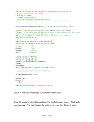
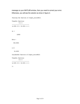
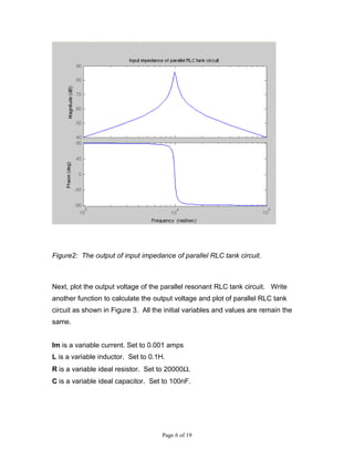
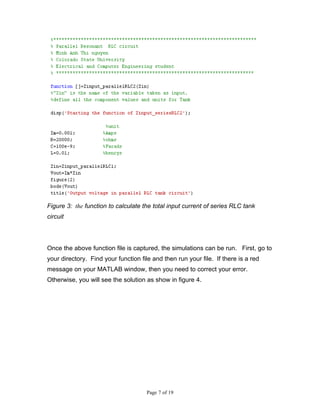
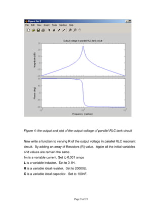
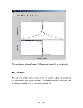
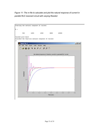
MATLAB SIMULATIONS OF PARALLEL RESONANT

                    CIRCUIT

        564: POWER ELECTRONICS III

        COLORADO STATE UNIVERSITY


  By Electrical and Computer Engineering Student

              Minh Anh Thi Nguyen


                     Page 1 of 19
PURPOSE: The purpose of this lab is to simulate the LCC circuit using
MATLAB® to better familiarize the student with some of its operating
characteristics. This lab will explore some of the following aspects of the buck
converter:


          Input impedance
          Output impedance
          Magnitude and phase margin
          Zero frequency
          Output power
          Output current
          Plot the natural response for the output voltage
          Zero poles
          Phase of transfer function
          Input impedance for varying loads resistance (R)
          Under damped
          Over damped
          Critical damp


NOTE: The simulations that follow are intended to be completed with MATLAB®.
It is assumed that the student has a fundamental understanding of the operation
of MATLAB®. MATLAB® provides tutorials for users that are not experienced with
its functions.
In this lab you will learn how to write a function to varying, calculating and
plotting the input impedance, current and output voltage of the series RLC
resonant tank circuit. Also plot the natural response of the parallel RLC tank
circuit.     You can define your own function in MATLAB. A function must start
with a line.
                 Function return-value = function-name (arguments)


                                        Page 2 of 19
So that MATLAB will recognize it as a function. Each function must have its own
file and the file must have the same as the function.


PROCEDURE:
Part 1: Write a function to calculate the total input impedance of parallel RLC
resonant circuit as shown in Figure 1.
Im is a variable current. Set to 0.001 amps
L is a variable inductor. Set to 0.1H.
R is a variable ideal resistor. Set to 20000Ω.
C is a variable ideal capacitor. Set to 100nF.


                                     Page 3 of 19
Figure 1: The input impedance of parallel RLC tank circuit.


Once the above function file is captured, the simulations can be run. First, go to
your directory. Find your function file and then run your file. If there is a red


                                      Page 4 of 19
message on your MATLAB window, then you need to correct your error.
Otherwise, you will see the solution as show in figure 2.


                                    Page 5 of 19
Figure2: The output of input impedance of parallel RLC tank circuit.


Next, plot the output voltage of the parallel resonant RLC tank circuit. Write
another function to calculate the output voltage and plot of parallel RLC tank
circuit as shown in Figure 3. All the initial variables and values are remain the
same.


Im is a variable current. Set to 0.001 amps
L is a variable inductor. Set to 0.1H.
R is a variable ideal resistor. Set to 20000Ω.
C is a variable ideal capacitor. Set to 100nF.


                                     Page 6 of 19
Figure 3: the function to calculate the total input current of series RLC tank
circuit


Once the above function file is captured, the simulations can be run. First, go to
your directory. Find your function file and then run your file. If there is a red
message on your MATLAB window, then you need to correct your error.
Otherwise, you will see the solution as show in figure 4.


                                      Page 7 of 19
Page 8 of 19
Figure 4: the output and plot of the output voltage of parallel RLC tank circuit


Now write a function to varying R of the output voltage in parallel RLC resonant
circuit. By adding an array of Resistors (R) value. Again all the initial variables
and values are remain the same.
Im is a variable current. Set to 0.001 amps
L is a variable inductor. Set to 0.1H.
R is a variable ideal resistor. Set to 20000Ω.
C is a variable ideal capacitor. Set to 100nF.


                                     Page 9 of 19
Write a loop function to do the varying resistors value, calculate and plot the
output voltage of parallel RLC resonant circuit. When the function to varying R
of the output voltage of parallel RLC resonant circuit function file is captured, the
simulations can be run. If there is any error message on your MATLAB
windows, then correct your error and then rerun the simulation. Otherwise, you
will see the result as show below


                                     Page 10 of 19
Figure 5: A function to calculate and plot of the output voltage in parallel RLC
resonant circuit with varying Resistor


                                    Page 11 of 19
Figure 6: Output voltage of parallel RLC resonant circuit with varying Resistor


For Homework:

You need to re-solve the parallel resonant circuit with inductor ESR and see its effects on
the magnitude and phase plots in some detail. For example choose the ratio of the L ESR
to the load resistance to be in the ratio range from 0.01 to 1.


                                         Page 12 of 19
Next write m file to varying R of the natural response of current in parallel RLC
resonant circuit. By adding an array of Resistors (R) value. Again all the initial
variables are remain the same but change their values.
Im is a variable current. Set to 1 volts
L is a variable inductor. Set to 39.487 H.
R is a variable ideal resistor. Set to 2000Ω.
C is a variable ideal capacitor. Set to 1µF
Io is a variable ideal of inductor current. Set to 0 amps.
Vo is a variable ideal of capacitor voltage. Set to 0 volts.


Write a loop function to do the varying resistors value, calculate and plot the
natural response of current for parallel RLC resonant circuit. When the m file to
varying R of the natural response of current in parallel RLC resonant circuit file is
captured, the simulations can be run. If there is any error message on your
MATLAB windows, then correct your error and then rerun the simulation.
Otherwise, you will see the result as show below


                                     Page 13 of 19
Page 14 of 19
Figure 11: The m file to calculate and plot the natural response of current in
parallel RLC resonant circuit with varying Resistor


                                    Page 15 of 19
Figure 12: This figure is shown the output of the natural responses of current in
                parallel RLC resonant circuit with varying Resistor


Now write m file to varying R of the natural response of output voltage in a
parallel RLC resonant circuit. By adding an array of Resistors (R) value. Again
all the initial variables are remain the same but change their values.


Im is a variable current. Set to 1 volts
L is a variable inductor. Set to 39.487 H.
R is a variable ideal resistor. Set to 2000Ω.
C is a variable ideal capacitor. Set to 1µF
Io is a variable ideal of inductor current. Set to 0 amps.
Vo is a variable ideal of capacitor voltage. Set to 0 volts.


Write a loop function to do the varying resistors value, calculate and plot the
natural response of output voltage in a parallel RLC resonant circuit. When the
m file to varying R of the natural response of parallel RLC resonant circuit file is
captured, the simulations can be run. If there is any error message on your
MATLAB windows, then correct your error and then rerun the simulation.
Otherwise, you will see the result as show below


                                     Page 16 of 19
Page 17 of 19
Figure 13: the m file to calculate and plot the natural response of current in a
             parallel RLC resonant circuit with varying Resistor


                                  Page 18 of 19
Figure 14: the output of the natural response of capacitor voltage in a parallel
                  RLC resonant circuit with varying Resistor


                                  Page 19 of 19

MATLAB SIMULATIONS OF PARALLEL RESONANT CIRCUIT

  • 1.
    MATLAB SIMULATIONS OFPARALLEL RESONANT CIRCUIT 564: POWER ELECTRONICS III COLORADO STATE UNIVERSITY By Electrical and Computer Engineering Student Minh Anh Thi Nguyen Page 1 of 19
  • 2.
    PURPOSE: The purposeof this lab is to simulate the LCC circuit using MATLAB® to better familiarize the student with some of its operating characteristics. This lab will explore some of the following aspects of the buck converter:  Input impedance  Output impedance  Magnitude and phase margin  Zero frequency  Output power  Output current  Plot the natural response for the output voltage  Zero poles  Phase of transfer function  Input impedance for varying loads resistance (R)  Under damped  Over damped  Critical damp NOTE: The simulations that follow are intended to be completed with MATLAB®. It is assumed that the student has a fundamental understanding of the operation of MATLAB®. MATLAB® provides tutorials for users that are not experienced with its functions. In this lab you will learn how to write a function to varying, calculating and plotting the input impedance, current and output voltage of the series RLC resonant tank circuit. Also plot the natural response of the parallel RLC tank circuit. You can define your own function in MATLAB. A function must start with a line. Function return-value = function-name (arguments) Page 2 of 19
  • 3.
    So that MATLABwill recognize it as a function. Each function must have its own file and the file must have the same as the function. PROCEDURE: Part 1: Write a function to calculate the total input impedance of parallel RLC resonant circuit as shown in Figure 1. Im is a variable current. Set to 0.001 amps L is a variable inductor. Set to 0.1H. R is a variable ideal resistor. Set to 20000Ω. C is a variable ideal capacitor. Set to 100nF. Page 3 of 19
  • 4.
    Figure 1: Theinput impedance of parallel RLC tank circuit. Once the above function file is captured, the simulations can be run. First, go to your directory. Find your function file and then run your file. If there is a red Page 4 of 19
  • 5.
    message on yourMATLAB window, then you need to correct your error. Otherwise, you will see the solution as show in figure 2. Page 5 of 19
  • 6.
    Figure2: The outputof input impedance of parallel RLC tank circuit. Next, plot the output voltage of the parallel resonant RLC tank circuit. Write another function to calculate the output voltage and plot of parallel RLC tank circuit as shown in Figure 3. All the initial variables and values are remain the same. Im is a variable current. Set to 0.001 amps L is a variable inductor. Set to 0.1H. R is a variable ideal resistor. Set to 20000Ω. C is a variable ideal capacitor. Set to 100nF. Page 6 of 19
  • 7.
    Figure 3: thefunction to calculate the total input current of series RLC tank circuit Once the above function file is captured, the simulations can be run. First, go to your directory. Find your function file and then run your file. If there is a red message on your MATLAB window, then you need to correct your error. Otherwise, you will see the solution as show in figure 4. Page 7 of 19
  • 8.
  • 9.
    Figure 4: theoutput and plot of the output voltage of parallel RLC tank circuit Now write a function to varying R of the output voltage in parallel RLC resonant circuit. By adding an array of Resistors (R) value. Again all the initial variables and values are remain the same. Im is a variable current. Set to 0.001 amps L is a variable inductor. Set to 0.1H. R is a variable ideal resistor. Set to 20000Ω. C is a variable ideal capacitor. Set to 100nF. Page 9 of 19
  • 10.
    Write a loopfunction to do the varying resistors value, calculate and plot the output voltage of parallel RLC resonant circuit. When the function to varying R of the output voltage of parallel RLC resonant circuit function file is captured, the simulations can be run. If there is any error message on your MATLAB windows, then correct your error and then rerun the simulation. Otherwise, you will see the result as show below Page 10 of 19
  • 11.
    Figure 5: Afunction to calculate and plot of the output voltage in parallel RLC resonant circuit with varying Resistor Page 11 of 19
  • 12.
    Figure 6: Outputvoltage of parallel RLC resonant circuit with varying Resistor For Homework: You need to re-solve the parallel resonant circuit with inductor ESR and see its effects on the magnitude and phase plots in some detail. For example choose the ratio of the L ESR to the load resistance to be in the ratio range from 0.01 to 1. Page 12 of 19
  • 13.
    Next write mfile to varying R of the natural response of current in parallel RLC resonant circuit. By adding an array of Resistors (R) value. Again all the initial variables are remain the same but change their values. Im is a variable current. Set to 1 volts L is a variable inductor. Set to 39.487 H. R is a variable ideal resistor. Set to 2000Ω. C is a variable ideal capacitor. Set to 1µF Io is a variable ideal of inductor current. Set to 0 amps. Vo is a variable ideal of capacitor voltage. Set to 0 volts. Write a loop function to do the varying resistors value, calculate and plot the natural response of current for parallel RLC resonant circuit. When the m file to varying R of the natural response of current in parallel RLC resonant circuit file is captured, the simulations can be run. If there is any error message on your MATLAB windows, then correct your error and then rerun the simulation. Otherwise, you will see the result as show below Page 13 of 19
  • 14.
  • 15.
    Figure 11: Them file to calculate and plot the natural response of current in parallel RLC resonant circuit with varying Resistor Page 15 of 19
  • 16.
    Figure 12: Thisfigure is shown the output of the natural responses of current in parallel RLC resonant circuit with varying Resistor Now write m file to varying R of the natural response of output voltage in a parallel RLC resonant circuit. By adding an array of Resistors (R) value. Again all the initial variables are remain the same but change their values. Im is a variable current. Set to 1 volts L is a variable inductor. Set to 39.487 H. R is a variable ideal resistor. Set to 2000Ω. C is a variable ideal capacitor. Set to 1µF Io is a variable ideal of inductor current. Set to 0 amps. Vo is a variable ideal of capacitor voltage. Set to 0 volts. Write a loop function to do the varying resistors value, calculate and plot the natural response of output voltage in a parallel RLC resonant circuit. When the m file to varying R of the natural response of parallel RLC resonant circuit file is captured, the simulations can be run. If there is any error message on your MATLAB windows, then correct your error and then rerun the simulation. Otherwise, you will see the result as show below Page 16 of 19
  • 17.
  • 18.
    Figure 13: them file to calculate and plot the natural response of current in a parallel RLC resonant circuit with varying Resistor Page 18 of 19
  • 19.
    Figure 14: theoutput of the natural response of capacitor voltage in a parallel RLC resonant circuit with varying Resistor Page 19 of 19