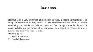
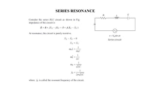
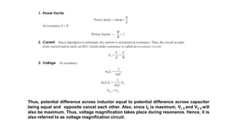
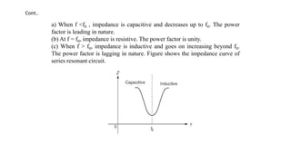
Resonance
Resonance is a very important phenomenon in many electrical applications. The
study of resonance is very useful in the telecommunication field. A circuit
containing reactance is said to be in resonance if the voltage across the circuit is in
phase with the current through it. At resonance, the circuit thus behaves as a pure
resistor and the net reactance is zero.
It is two types
1. Series Resonance
2. Parallel Resonance
SERIES RESONANCE
Thus, potential difference across inductor equal to potential difference across capacitor
being equal and opposite cancel each other. Also, since I0 is maximum, VL 0 and VC 0 will
also be maximum. Thus, voltage magnification takes place during resonance. Hence, it is
also referred to as voltage magnification circuit.
Phasor Diagram
Below figure shows the phasor diagram of a series resonant circuit
Figure :Phasor diagram
Behavior of R, L and C with Change in Frequency
Resistance remains constant with the change in frequencies. Inductive reactance XL is
directly proportional to frequency f. It can be drawn as a straight line passing through the
origin. Capacitive reactance XC is inversely proportional to the frequency f. It can be
drawn as a rectangular hyperbola in the fourth quadrant. Below figure shows the
behavior of R, L and C with change in frequency.
Total impedance Z = R + j (XL − XC )
Figure: Behavior of R, L and C with change in
frequency
a) When f <f0 , impedance is capacitive and decreases up to f0. The power
factor is leading in nature.
(b) At f = f0, impedance is resistive. The power factor is unity.
(c) When f > f0, impedance is inductive and goes on increasing beyond f0.
The power factor is lagging in nature. Figure shows the impedance curve of
series resonant circuit.
Cont..
Bandwidth
For the series RLC circuit, bandwidth is defined as the range of frequencies for which the
power delivered to R is greater than or equal to P0/2 where P0 is the power delivered to R at
resonance. From the shape of the resonance curve shown in below Fig., it is clear that there
are two frequencies for which the power delivered to R is half the power at resonance. For this
reason, these frequencies are referred as those corresponding to the half-power points. The
magnitude of the current at each half power point is the same.
Resonance Curve
Cont..
Expression for Bandwidth
Cont..
PARALLEL RESONANCE
Cont..
The bandwidth of a parallel resonant circuit is defined in the same way as that for a
series resonant circuit. Below figure shows the resonance curve of a parallel resonant
circuit.
Bandwidth
THANK YOU

lect3_resonance.pptx

  • 3.
    Resonance Resonance is avery important phenomenon in many electrical applications. The study of resonance is very useful in the telecommunication field. A circuit containing reactance is said to be in resonance if the voltage across the circuit is in phase with the current through it. At resonance, the circuit thus behaves as a pure resistor and the net reactance is zero. It is two types 1. Series Resonance 2. Parallel Resonance
  • 4.
  • 5.
    Thus, potential differenceacross inductor equal to potential difference across capacitor being equal and opposite cancel each other. Also, since I0 is maximum, VL 0 and VC 0 will also be maximum. Thus, voltage magnification takes place during resonance. Hence, it is also referred to as voltage magnification circuit.
  • 6.
    Phasor Diagram Below figureshows the phasor diagram of a series resonant circuit Figure :Phasor diagram
  • 7.
    Behavior of R,L and C with Change in Frequency Resistance remains constant with the change in frequencies. Inductive reactance XL is directly proportional to frequency f. It can be drawn as a straight line passing through the origin. Capacitive reactance XC is inversely proportional to the frequency f. It can be drawn as a rectangular hyperbola in the fourth quadrant. Below figure shows the behavior of R, L and C with change in frequency. Total impedance Z = R + j (XL − XC ) Figure: Behavior of R, L and C with change in frequency
  • 8.
    a) When f<f0 , impedance is capacitive and decreases up to f0. The power factor is leading in nature. (b) At f = f0, impedance is resistive. The power factor is unity. (c) When f > f0, impedance is inductive and goes on increasing beyond f0. The power factor is lagging in nature. Figure shows the impedance curve of series resonant circuit. Cont..
  • 9.
    Bandwidth For the seriesRLC circuit, bandwidth is defined as the range of frequencies for which the power delivered to R is greater than or equal to P0/2 where P0 is the power delivered to R at resonance. From the shape of the resonance curve shown in below Fig., it is clear that there are two frequencies for which the power delivered to R is half the power at resonance. For this reason, these frequencies are referred as those corresponding to the half-power points. The magnitude of the current at each half power point is the same. Resonance Curve
  • 10.
  • 11.
  • 12.
  • 22.
  • 23.
  • 26.
    The bandwidth ofa parallel resonant circuit is defined in the same way as that for a series resonant circuit. Below figure shows the resonance curve of a parallel resonant circuit. Bandwidth
  • 33.