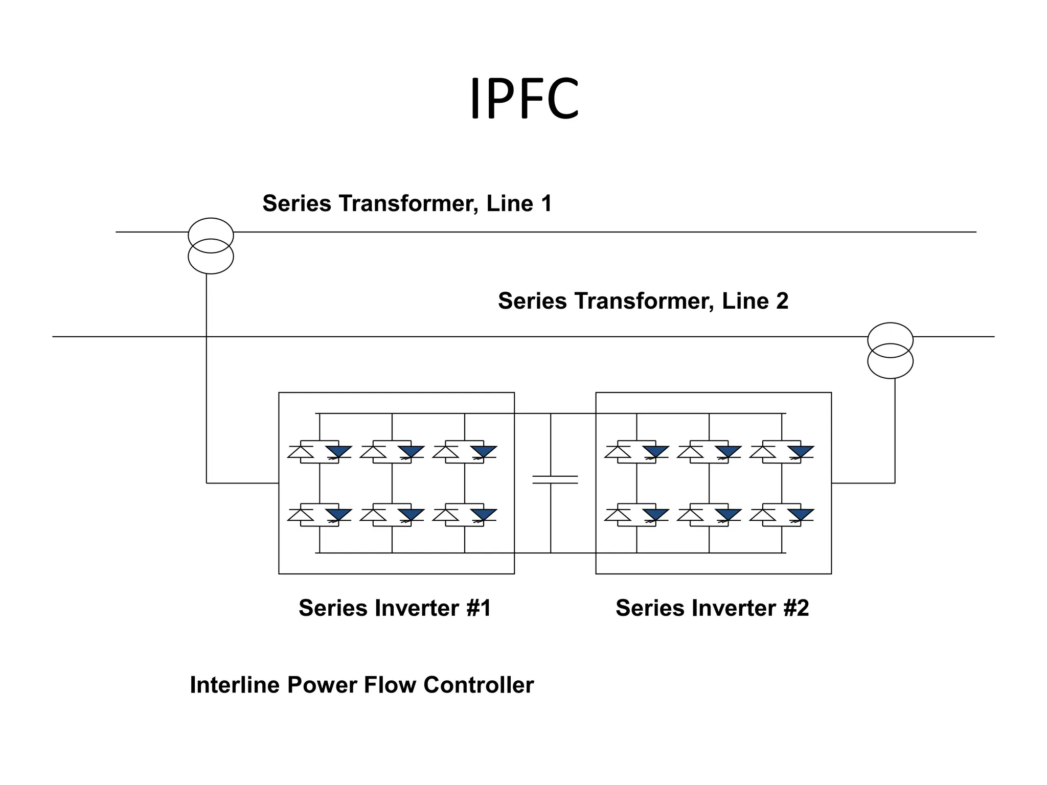
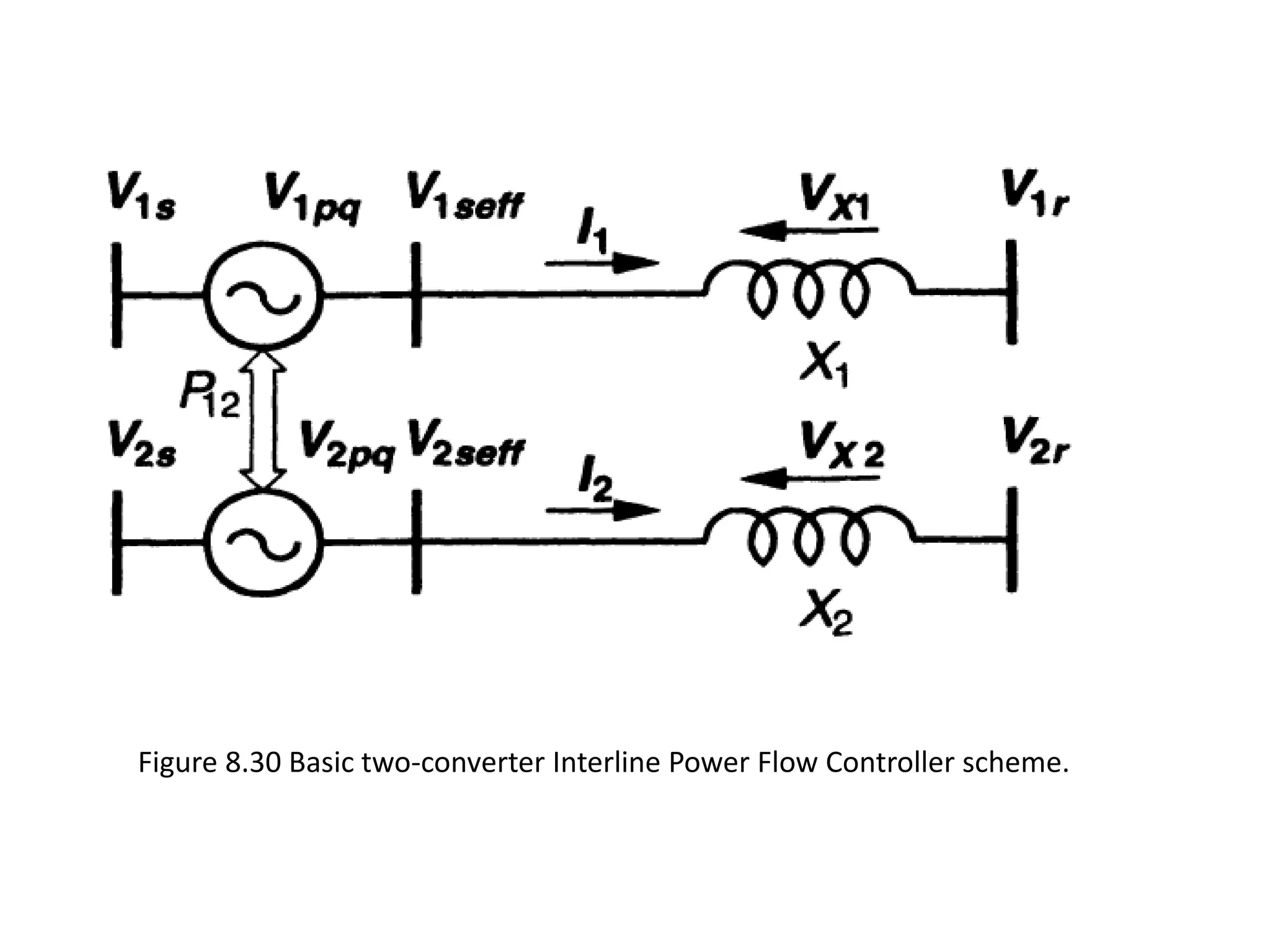
IPFC
Dr.K.Ravi
• Similar in configuration to UPFC
• The shunt inverter is used as an active filter
• The series injection is used to mitigate voltage sags and
swells.
• However, independent of their means of
implementation,
• series reactive compensators are unable to control the
reactive power flow in, and thus the proper load
balancing of, the lines.
• This problem becomes particularly evident in those
cases where the ratio of reactive to resistive line
impedance (X/R)is relatively low.
Interline Power Flow Conditioner
• Series reactive compensation reduces only the
effective reactive impedance X and, thus,
significantly decreases the effective X/R ratio
and thereby increases the reactive power flow
and losses in the line.
• The IPFC scheme, together with
independently controllable reactive series
compensation of each individual line, provides
a capability to directly transfer real power
between the compensated lines.
• This capability makes it possible to: equalize both
real and reactive power flow between the lines;
• reduce the burden of overloaded lines by real
power transfer;
• Compensate against resistive line voltage drops
and the corresponding reactive power demand;
• and increase the effectiveness of the overall
compensating system for dynamic disturbances.
• In other words, the IPFC can potentially provide a
highly effective scheme for power transmission
management at a multiline substation.
Basic Operating Principles and
Characteristics
• the IPFC comprises a number of Static
Synchronous Series Compensators.
• However, within the general concept of the
IPFC, the compensating converters are linked
together at their dc terminals as shown in
fig.8.29
• in addition to providing series reactive compensation, any
converter can be controlled to supply real power to the
common dc link from its own transmission line.
• Thus, an overall surplus power can be made available from
the under utilized lines which then can be used by other lines
for real power compensation.
• In this way, some of the converters, compensating overloaded
lines or lines with a heavy burden of reactive power flow, can
be equipped with full two-dimensional, reactive and real
power control capability, similar to that offered by the UPFC.
• Evidently, this arrangement mandates the rigorous
maintenance of the overall power balance at the common dc
terminal by appropriate control action, using the general
principle that the under loaded lines are to provide help, in
the form of appropriate real power transfer, for the
overloaded lines.
• Consider an elementary IPFC scheme consisting
of two back-to-back dc-to-ac converters, each
compensating a transmission line by series
voltage injection.
• This arrangement is shown functionally in Figure
8.30, where two synchronous voltage sources,
with phasors V1pq and V2pq in series with
transmission Lines 1 and 2, represent the two
back-to-back dc-to-ac converters.
• The common dc link is represented by a
bidirectional link for real power exchange
between the two voltage sources.
IPFC
Series Inverter #1 Series Inverter #2
Interline Power Flow Controller
Series Transformer, Line 2
Series Transformer, Line 1
Figure 8.30 Basic two-converter Interline Power Flow Controller scheme.
• Transmission Line 1, represented by reactance X1, has a
sending-end bus with voltage phasor V1s and a receiving-
end bus with voltage phasor V1r.
• The sending-end voltage phasor of Line 2, represented by
reactance X2, is V2s and the receiving-end voltage phasor
isV2r•
• For clarity, all the sending-end and receiving-end voltages
are assumed to be constant with fixed amplitudes, V1s =
V1r = V2s = V2r = 1.0 p.u., and with fixed angles resulting in
identical transmission angles, δ1 = δ2 (= 30°), for the two
systems.
• The two line impedances, and the rating of the two
compensating voltage sources, are also assumed to be
identical, i.e., V1pqmax = V2pqmax and X1 = X 2 = 0.5 p.u.,
respectively.
• Although Systems 1 and 2 could be (and in practice are
likely to be) different (i.e., different transmission line
voltage, impedance, and angle),

17-conventional transmission control capabilities; Interline Power Flow Controller_-20-02-2024.ppt

  • 1.
  • 2.
    • Similar inconfiguration to UPFC • The shunt inverter is used as an active filter • The series injection is used to mitigate voltage sags and swells. • However, independent of their means of implementation, • series reactive compensators are unable to control the reactive power flow in, and thus the proper load balancing of, the lines. • This problem becomes particularly evident in those cases where the ratio of reactive to resistive line impedance (X/R)is relatively low. Interline Power Flow Conditioner
  • 3.
    • Series reactivecompensation reduces only the effective reactive impedance X and, thus, significantly decreases the effective X/R ratio and thereby increases the reactive power flow and losses in the line. • The IPFC scheme, together with independently controllable reactive series compensation of each individual line, provides a capability to directly transfer real power between the compensated lines.
  • 4.
    • This capabilitymakes it possible to: equalize both real and reactive power flow between the lines; • reduce the burden of overloaded lines by real power transfer; • Compensate against resistive line voltage drops and the corresponding reactive power demand; • and increase the effectiveness of the overall compensating system for dynamic disturbances. • In other words, the IPFC can potentially provide a highly effective scheme for power transmission management at a multiline substation.
  • 5.
    Basic Operating Principlesand Characteristics • the IPFC comprises a number of Static Synchronous Series Compensators. • However, within the general concept of the IPFC, the compensating converters are linked together at their dc terminals as shown in fig.8.29
  • 7.
    • in additionto providing series reactive compensation, any converter can be controlled to supply real power to the common dc link from its own transmission line. • Thus, an overall surplus power can be made available from the under utilized lines which then can be used by other lines for real power compensation. • In this way, some of the converters, compensating overloaded lines or lines with a heavy burden of reactive power flow, can be equipped with full two-dimensional, reactive and real power control capability, similar to that offered by the UPFC. • Evidently, this arrangement mandates the rigorous maintenance of the overall power balance at the common dc terminal by appropriate control action, using the general principle that the under loaded lines are to provide help, in the form of appropriate real power transfer, for the overloaded lines.
  • 8.
    • Consider anelementary IPFC scheme consisting of two back-to-back dc-to-ac converters, each compensating a transmission line by series voltage injection. • This arrangement is shown functionally in Figure 8.30, where two synchronous voltage sources, with phasors V1pq and V2pq in series with transmission Lines 1 and 2, represent the two back-to-back dc-to-ac converters. • The common dc link is represented by a bidirectional link for real power exchange between the two voltage sources.
  • 9.
    IPFC Series Inverter #1Series Inverter #2 Interline Power Flow Controller Series Transformer, Line 2 Series Transformer, Line 1
  • 10.
    Figure 8.30 Basictwo-converter Interline Power Flow Controller scheme.
  • 11.
    • Transmission Line1, represented by reactance X1, has a sending-end bus with voltage phasor V1s and a receiving- end bus with voltage phasor V1r. • The sending-end voltage phasor of Line 2, represented by reactance X2, is V2s and the receiving-end voltage phasor isV2r• • For clarity, all the sending-end and receiving-end voltages are assumed to be constant with fixed amplitudes, V1s = V1r = V2s = V2r = 1.0 p.u., and with fixed angles resulting in identical transmission angles, δ1 = δ2 (= 30°), for the two systems. • The two line impedances, and the rating of the two compensating voltage sources, are also assumed to be identical, i.e., V1pqmax = V2pqmax and X1 = X 2 = 0.5 p.u., respectively. • Although Systems 1 and 2 could be (and in practice are likely to be) different (i.e., different transmission line voltage, impedance, and angle),