This document describes a system to remotely monitor and control devices using GSM technology. The system uses a microcontroller to receive SMS commands from a mobile phone via a GSM modem and control devices connected to relays. It allows devices like fans and lamps to be turned on and off from a distance. The system provides advantages like remote control from anywhere using basic phone operation and potential applications in home, office, and industrial automation.
CONTENTS Objective IntroductionBlock Diagram Working Principle Advantages Applications Limitations Future Scope of Work Conclusion
3.
OBJECTIVE The objectiveof this project is to design and develop a wireless communication link to monitor and control equipments that are far away from the user and also develop a high security system to keep a check on them .
4.
INTRODUCTION The proposedsystem is based on ATMEL 89S52 microcontroller. The transmitter is a mobile phone which uses certain codes corresponding to a particular relay to which the device is connected. At the receiver, the GSM modem receives the message from the mobile phone and gives it to the microcontroller which acts to control the devices.
5.
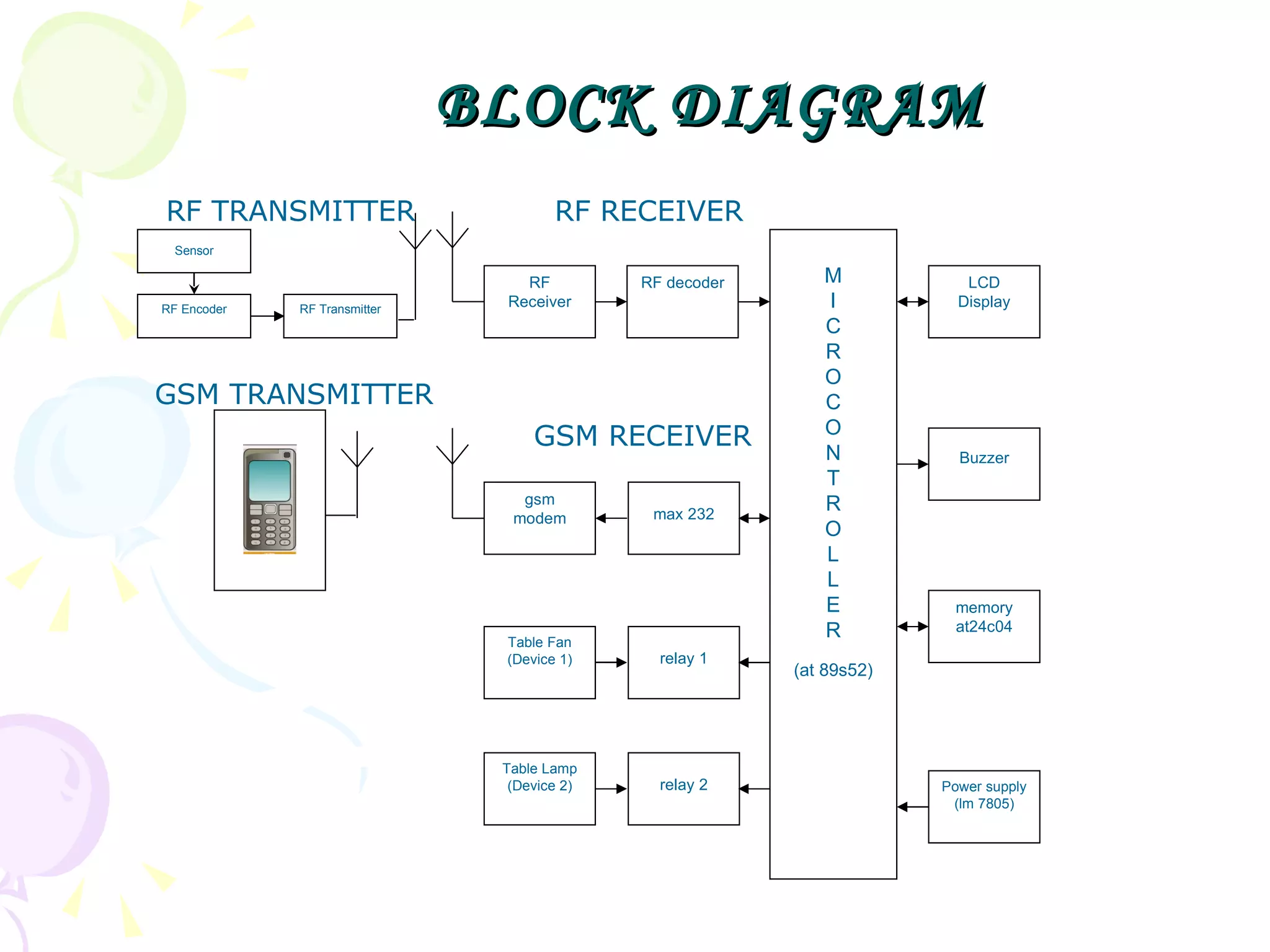
BLOCK DIAGRAM RFTRANSMITTER RF RECEIVER GSM TRANSMITTER GSM RECEIVER RF Receiver M I C R O C O N T R O L L E R (at 89s52) RF decoder gsm modem max 232 Table Fan (Device 1) relay 1 Table Lamp (Device 2) relay 2 LCD Display Buzzer memory at24c04 Power supply (lm 7805) Sensor RF Encoder RF Transmitter
6.
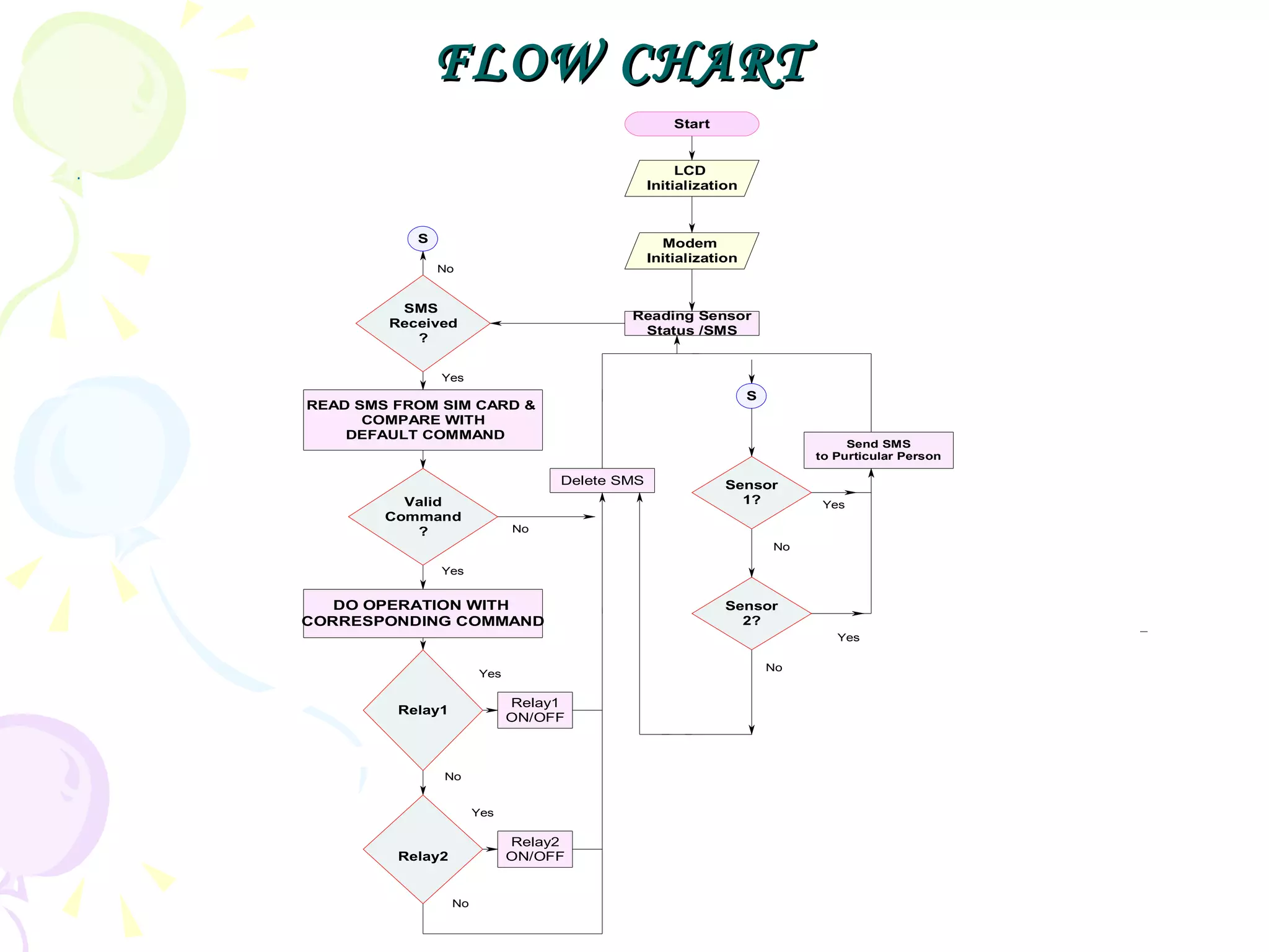
WORKING PRINCIPLE Atthe transmitter side, the user sends an SMS to the GSM modem using AT commands indicating which device is to be controlled. At the receiver side, Microcontroller controls the devices through relays depending on the code received by the GSM modem.
7.
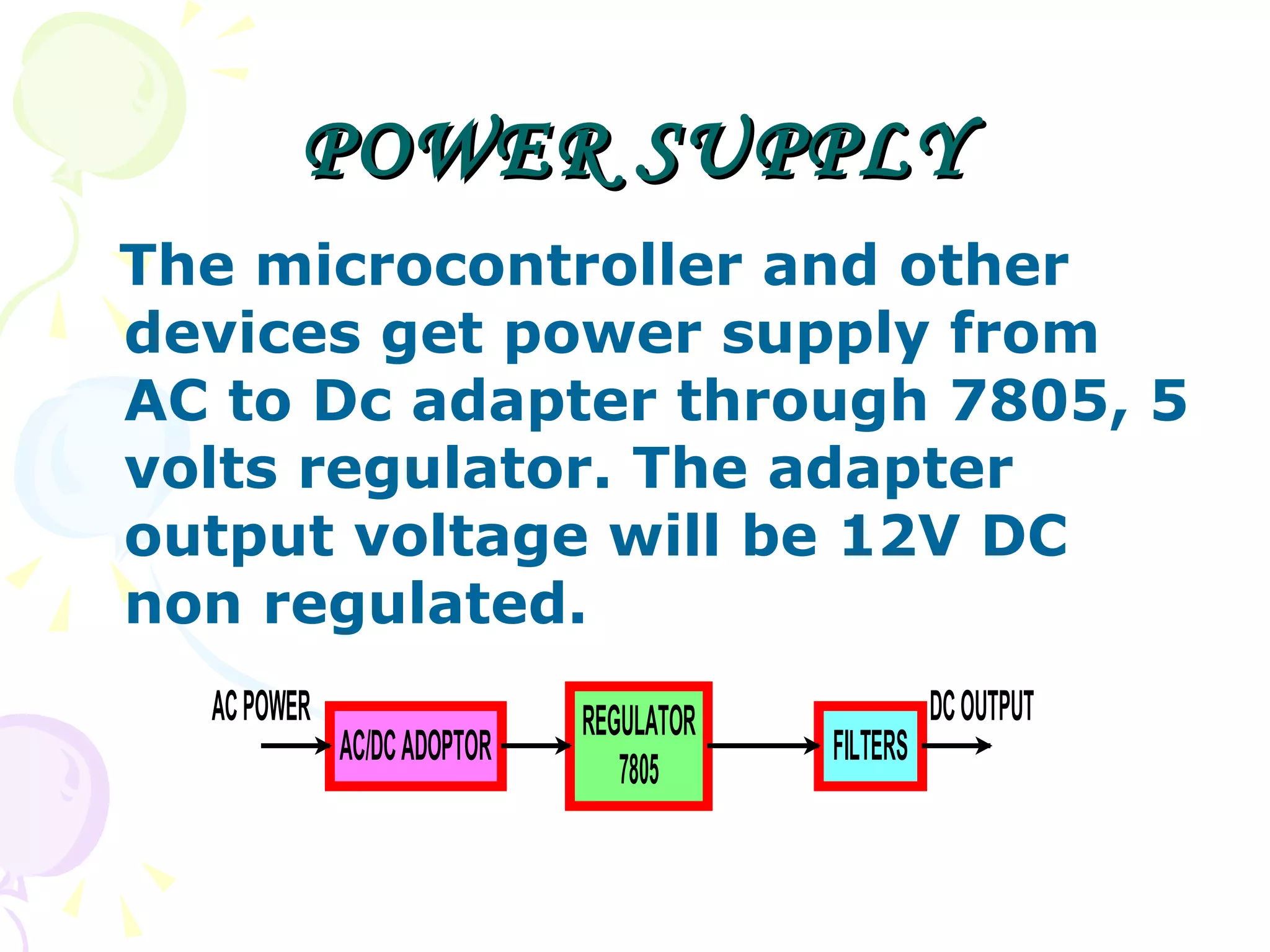
POWER SUPPLY Themicrocontroller and other devices get power supply from AC to Dc adapter through 7805, 5 volts regulator. The adapter output voltage will be 12V DC non regulated.
8.
GSM MODEM GSMModem is a multi-functional, ready to use, rugged unit that can be embedded or plugged into any application. The Modem can be controlled and customized to various levels by using the standard AT commands.
9.
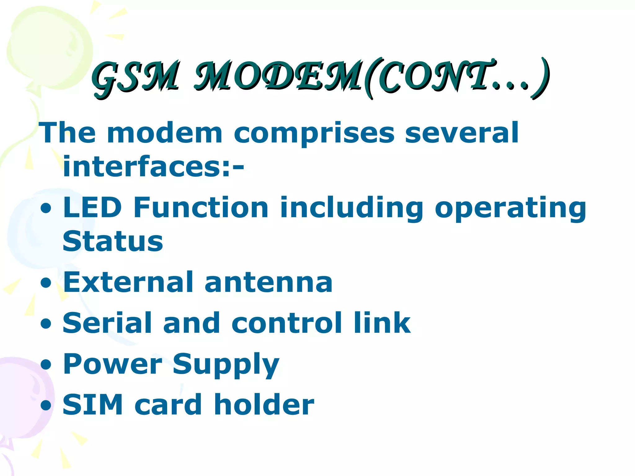
GSM MODEM(CONT…) Themodem comprises several interfaces:- LED Function including operating Status External antenna Serial and control link Power Supply SIM card holder
10.
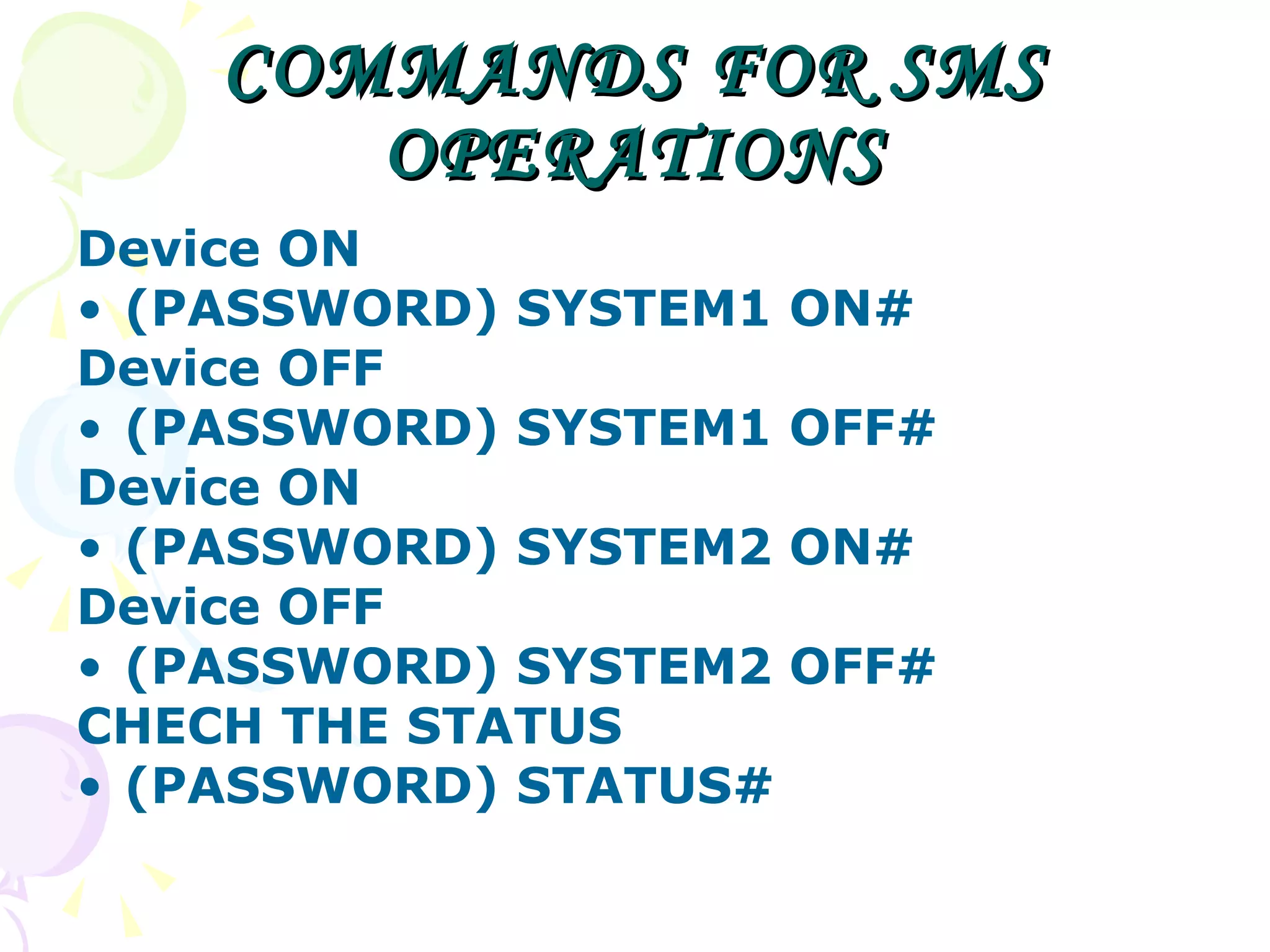
COMMANDS FOR SMSOPERATIONS Device ON (PASSWORD) SYSTEM1 ON# Device OFF (PASSWORD) SYSTEM1 OFF# Device ON (PASSWORD) SYSTEM2 ON# Device OFF (PASSWORD) SYSTEM2 OFF# CHECH THE STATUS (PASSWORD) STATUS#
11.
MICROCONTROLLER-AT89S52 The AT89S52is a low-power, high-performance CMOS 8-bit micro controller with 8K bytes of in-system programmable Flash memory. The device is manufactured using Atmel’s nonvolatile memory technology . It is a powerful microcontroller which provides a highly-flexible, cost effective solution to many embedded control applications. The code written is downloaded into the microcontroller chip using an universal programmer.
12.
MAX232 MAX232 wascreated for one purpose, to interface between Data Terminal Equipment (DTE) and Data Communications Equipment (DCE) employing serial binary data interchange. So as stated the DTE is the terminal or computer and the DCE is the modem or other communications device.
13.
EEPROM electricallyerasable and programmable read only memory (EEPROM) is organized as words of 8 bits each. Features: 2-Wire Serial Interface (I2C protocol) High Reliability Vital role of External EEPROM memory : To store the status of the relay switches.
14.
I2C The STARTcondition acts as a signal to all connected IC's that something is about to be transmitted on the bus. A STOP condition is sent. This is the signal for all devices on the bus that the bus is available again (idle).
15.
RELAY Relays usean electromagnetic coil to move the poles of a switch when powered. There are three pairs of connections known as common, normally open and normally closed. The center terminal block is the common (CO) connection and is connected to either the upper or lower terminal block depending on the state of the relay. Vital role of RELAY: Switch on/off the device according to the microcontroller commands.
16.
PCB A printedcircuit board, or PCB, is used to mechanically support and electrically connect electronic components using conductive pathways. electronic component have wire leads, and the PCB has holes drilled for each wire of each component. The components' leads are then passed through the holes and soldered to the PCB trace.
ADVANTAGES The statusof various devices can be monitored and controlled from anywhere. The operation of the system is very simple and can be used by anyone with a basic knowledge of operating mobile phones. Easy to upgrade as per the user requirement.
19.
APPLICATIONS Home AutomationOffice Automation Industrial Automation To control water pump sets in agricultural fields. The security system can be employed in household or any organization.
20.
LIMITATIONS If themain module or the handset is not in the cellular range ,we can’t control the devices. The sensors use RF transmitter and receiver which has limited range, hence sensors have to be in close vicinity of the main module
21.
FUTURE SCOPE OFWORK It can be used for high security in banks and other organizations. Using real time clock, the appliances which need response in real time can also be Controlled through the wireless link . Connecting More Devices. Provision To Store Several Mobile Numbers Video Recording Once Alarm Gets Triggered
22.
CONCLUSION We presentedan approach that can be employed to improve the performance of various devices that are not in the close vicinity of the user. The usability of the design was verified by controlling a table fan and a table lamp. The user was informed about the action through a reply SMS sent by the modem at the receiver.