SlideShare a Scribd company logo
REACTOR KINETICS &DIFFERENT TYPES OF
UREA REACTOR HIGH EFFICIENCY TRAYS
Author
Prem Baboo
Sr. Manager (Prod)
National fertilizers Ltd, India
Mob. +919425735974
prem.baboo@nfl.co.in ,pbaboo@hotmail.com
An Expert for www.ureaknowhow.com
Fellow of Institution of Engineers (India)
PURPOSE
1. The main purpose HET to improve the redistribution of unreacted carbon
dioxide inside the liquid phase rich in free ammonia.
2. To reduce the back mixing phenomenon due to density increase of carbamate
and urea solution from bottom to reactor top.
3. To reduce also channelling which has a negative effect on the solution residence
time.
ADVANTAGES
The activity contributes to environmental and social aspects and eventually to
sustainable development by: Reduction of consumption of non - renewable fuel like NG,
which is a step towards conserving natural resources. Reducing steam consumption
which results in reduction in energy consumption.
Steam is used in the strippers and varies proportionately with the urea production. Due
to the improved conversion efficiency of the process (again due to improved tray design
and increased number of trays), the steam utilisation in the overall manufacturing
process has reduced. Hence the parameter of the specific consumption of steam to urea
gives a clear indication of the energy saved. As elaborated above, the specific
consumption of the steam to urea forms the critical parameter and hence the urea
production and accordingly the steam consumptions are monitored.
Fig.-1
A typical reactor therefore contains a gaseous phase and a liquid phase flowing in co-current
flows inside a pressurized reaction chamber. Conversion of ammonia and carbon dioxide to
ammonium carbonate and ultimately urea is enhanced as fig-1, i.e. to increase urea output,
using tray reactors. Urea tray reactors substantially comprise a normally cylindrical shell, which
extends substantially along a normally vertical axis, and is fitted inside with elements, i.e. trays,
defined by respective metal sections shaped and/or perforated to divide the reaction chamber
into compartments and form specific paths for the substances inside the reactor. The trays are
normally perpendicular to the vertical axis of the reactor, and equally spaced along the axis to
the full height of the reactor. The trays are very often perforated, i.e. have holes variously
arranged and possibly of different shapes and/or sizes. Fluid dynamics and its influence on
heat and mass transport rates in gas–liquid reactors is, in general, an important starting
point for development of a process design. Improvements in the understanding of these
aspects can be particularly fruitful in the case of urea reactors where the fluid-dynamic
patterns are complicated by the co-current flow of two phases and the bubbling mode of
the vapours. The analysis of such systems highlighted the non-optimal design of existing
reactors and led to the conception of new reactor internals. Several industrial
applications demonstrate the ability of the new configuration to improve reactor
efficiency. Both energy-saving and production increases were obtained. This is a further
demonstration that even mature technologies can be improved, leading not only to
economic advantages, but also to a reduction in their environmental impact. With
CO2conversion in the reactor ranging from 56 to 70%, depending on the particular
technology adopted, efforts to obtain improvements have mostly been addressed to the
recycle system. The efficiency of the synthesis reactor itself has been particularly under
evaluated, probably following the common conviction that the optimum performance
had already been achieved. Urea reactors consist of cylindrical vessels (generally 20–40
m high), having diameters from 1 to 3 m, containing, in most cases, several trays
giving rise to a stage-wise structure. The aim is to reduce axial back mixing and
redistribute the vapour phase. Some-times, reactors operating at high NH3/CO2 ratios
and pressures, and having relatively small diameters, are used without trays. In the
most widespread process configurations, the unconverted reactants are recycled to the
reactor through a series of decreasing pressure stages using heat provided by steam.
The higher the CO2 conversion, the smaller the amount of heat and the size of the
equipment needed to reach a certain capacity. During the formation of urea, vapour
and liquid are present all along the reactor, flowing co-
Currently and exchanging mass and enthalpy fluxes through their interfaces. As the
process is also characterized by reversible reactions, the overall behaviour is
controlled by both physical and chemical equilibrium, coupled with physical and
chemical kinetics.
The trays are preferably designed for insertion through the manhole reactors are
normally provided with, so they can also be fitted to existing reactors and/or removed
and replaced. For which reason, the trays are normally made in a number of parts that
fit together.
The trays have various functions, and in particular:
1. Maximize the hold time of the light (faster) phase; distribute the reactants as
evenly as possible along the reactor section, to prevent back-mixing’;
2. Enhance mixing of the gaseous- and liquid phases; and
3. Reduce bubble size' to improve diffusion of the ammonia in the carbon dioxide.
Numerous urea reactor tray designs and configurations are known.
The Principle of high efficiency trays:-
1. Mass transfer factor
2. Contact pattern of phase
3. Fluid dynamics factors
4. Interfacial surface area
5. Geometry of reactor vessel
6. Chemical kinetics factors
7. Temperature & pressure
Generally speaking, known solutions fail to provide for thorough mixing of the light
and heavy phases (both consisting of supercritical fluids) , which, because of the
difference in density, tend to flow along separate preferential paths defined by the
design and arrangement of the trays, and in particular by the shape, location, and
size of the holes in the trays. This drawback also impairs final conversion of the
reactants, thus reducing urea output.
1. The geometry of the reactor tray according to the present invention provides for
thoroughly mixing the gaseous and liquid phases in a urea reactor and urea
production process, and so greatly increasing urea output.
2. The reactor tray according to the present invention and the reactor as a whole
are also extremely easy to produce and install.
3. Urea producers can reduce consumption and/or increase production of their
plants by introducing the various revamping technologies developed
The installation high efficiency trays are giving an increased production of urea and
reduced steam consumption; the financial benefits are determined by the urea sales and
energy prices. It has been demonstrated that the installation of high efficiency reactor
trays in existing urea plant is very profitable.
THE USE OF REACTION KINETICS TOIMPROVE THE CONVERSION IN
VERTICAL UREAREACTORS
The conversion of Carbamate into urea is a relatively slow reaction and requires heat.
Non converted ammonia and carbon dioxide, passing the high-pressure carbamate
condenser, supply the heat needed for this reaction. Because of the equilibrium
reaction, the reaction is preferably done in a plug flow type of reactor. Installing a
number of continuous stirred tank reactors in series can approach plug flow. Thus the
urea reactor is divided into a number of compartments, mostly separated with sieve
trays, and each compartment acts as a continuous stirred tank reactor. As a result plug
flow is approached in such a cascade type reactor.
Fig.-2(a) Fig.-2(b)
To obtain a continuous stirred tank reactor, stirrers should be applied. However urea
reactors are not equipped with mechanical stirrers. The driving force for mixing the
liquid in the compartments of the reactor is the gas phase. The urea reactor is a so-
called high-pressure bubble column. By adding the gas phase through the center of a
compartment via carefully designed holes, a Torus circulation exists and thus the
required mixing of the liquid in such a compartment is obtained, as fig. 2(a) the
principle of such a Torus circulation exists and thus the required mixing of the liquid in
such a way Compartments obtained. The principle of such a torus circulation is shown
in the figure.Because the urea reaction is a relatively slow equilibrium reaction a
relative large retention time in the reactor is needed to approach the maximum
equilibrium level. Fig.-3, However an infinite large reactor volume is required to reach
this equilibrium. For economic reasons the installed reactor volume in the designing of
urea plants is such that the fraction approach to equilibrium (FAE) is 95 percent. The
fraction approach to equilibrium is defined as:
FAE = 100* ήC02 actual/ ή C02 equilibrium
Fig.-3
Retention
F.A.E
ή co2
The relation between the fraction approach to equilibrium and the retention is shown in Fig.
In large-scale urea plants (> 1500 MTPD), equipped with reactors with large diameters and
conventional type reactor trays, it is observed that the expected fraction approach to
equilibrium is not reached resulting in a relative low reactor conversion. The consequence is
that at a specified plant capacity the steam consumption on the high-pressure stripper is
larger than expected. The reason for the observed relative low reactor conversion was a
non-optimal mixing rate in the urea reactor compartments and, thus, these compartments
did not act as an optimal continuous stirred tank reactor. The non-optimal mixing behavior
in such reactors can be caused by:
1. Back mixing
2. Channeling (fig-5,a)
3. Stagnant zones
Back mixing occurs when the liquid phase passes the sieve trays through the gas holes. This
occurs when the height of the gas cushion below the sieve tray is small. In reactors with large
diameters, when the reactor tray is not perfectly horizontal then the
. gas holes are in contact with the liquid phase. This is illustrated in
Fig.-4
Reactors with a relative large diameter are sensitive for stagnant zones. Stagnant zones
are caused by poor mixing in the compartments and have a negative impact on the
reactor conversion since the compartments will not optimally act as the required
continuous stirred tank reactor. To avoid the negative effects of back mixing and
channeling, Stamicarbon developed in the beginning of the 90’s the high efficiency trays
as illustrated in the fig.
Channeling occurs when the liquid phase is partly bypassing a compartment. In urea
reactors, equipped with conventional sieve trays, the liquid is transported from the one
compartment to the other compartment via the annular spacing between the tray and
the reactor wall. In urea reactors with large diameters it appears that the mixing rate by
the Torus circulation may not be large enough to avoid these channeling effects. The
channeling effect is shown in Fig.
Fig.-5(a) Fig-5(b)
HIGH EFFICIENCY TRAYS, HET
These high efficiency reactor trays are equipped with liquid risers where the liquid
enters the following compartment. By staggering the liquid risers, the liquid is forced
into the Torus circulation and channeling is eliminated. To avoid back mixing, the gas
cushions were increased and this makes the trays less sensitive to horizontal variations
of the tray. Because the conversion of carbamate into urea is an equilibrium reaction,
the reaction is preferably done in a plug flow type of reactor; that is to say, one in which
the flow of reaction medium is uniform and non-turbulent over the entire cross-section
of the reactor interior. It is difficult to prevent turbulence and back mixing in a large
unconfined body of fluid; however, an approximation to overall plug flow can be
attained in a number of continuous stirred tank reactors arranged in series. Therefore
the urea reactor is divided into a number of compartments, separated from one another
by sieve trays, and each compartment emulates a continuously-stirred tank reactor. The
driving force for mixing the liquid in the compartments of the reactor is the gas phase.
By forcing the gas phase to pass through the centre of a compartment via carefully
designed holes, a Torus-shaped circulation prevails and thus the required mixing of the
liquid in such a compartment is obtained. However, in larger reactors non-optimal
mixing behaviour has been identified and investigated. Identified causes were back
mixing, channelling and stagnant zones. To address that problem, Stamicarbon has
developed a new generation of high efficiency trays known as Siphon Jet Pump trays.
The compartments, separated by sieve trays, are equipped with a draft tube. Inside the
draft tube there is a two-phase flow of gas and liquid. The effective density of this two-
phase flow is considerably lower than the liquid density on the outside of the draft tube,
and the density difference further enhances liquid circulation, promoting mixing. The
deflector plates in the pool reactor and pool condenser, which work on the same
principle as the draft tube, have amply proved this effect. Using Siphon Jet Pump trays
provides the closest approach to a continuous stirred tank reactor without necessitating
any mechanical agitation. The mixing rate is increased significantly and the negative
effects of back-mixing and channelling are avoided. The first Siphon Jet Pump trays
were installed at SKW Piesteritz, and the result was so satisfactory that Siphon Jet
Pumps have been installed in all three plants and are currently in operation. They have
had the effect not only of making operations very smooth and raising the capacity of the
existing plants, but also of reducing the HP steam requirement of the HP stripper.
Amongst others, Fauji Pakistan, ABF Malaysia and Qafco Qatar have also installed iphon
Jet Pumps in their
Although the high efficiency trays 'improved the reactor efficiency significantly, they did
not improve the mixing rate. The mixing is still reliant upon the Torus circulation. In
practice it appeared to be difficult to keep the strict tolerances for the gap between the
reactor tray and the reactor wall because of the no roundness of the reactor. To improve
the mixing rate in the reactor compartment sand to avoid strict Mechanical tolerances,
Stamicarbon recently developed a new generation of H.E.T. Known as siphon jet pumps
Fig.-6
The compartments, separated by sieve trays, are equipped with a draft tube. Inside
the draft tube there is a two-phase flow with the density of this two-phase flow
being considerably less than the liquid density at the outside of the draft tube. By
this density difference liquid circulation is enhanced further stimulating the
mixing. The deflector plates in the pool reactor and pool condenser, in which the
deflector plates have a similar function as the proposed draft tube, have proved
these phenomena
Because of this heavy circulation effect and thus improved mixing rate it is no
longer necessary to equip the reactor trays with liquid risers. The liquid can
enter the following Compartment via the annular spacing between the tray and
the reactor wall in a similar fashion as the conventional Reactor trays. The strict
tolerance regarding the gap between The tray and the reactor wall for the new
generation HET is No longer required
The first Siphon Jet Pumps were installed in one of the plants of SKW Piesteritz.
Because the trays were operating very satisfactory, two other reactors of SKW
Piesteritz are now also operating with Siphon Jet Pumps. In the following table
the current references for Siphon Jet Pumps are presented.
Table-1
Client
Capacity Year in Number of New/Modified
(MTPD) operation trays trays
SKW Piesteritz 3 1050 2001 11 New
SKW Piesteritz 1 1050 2002 11 New
SKW Piesteritz 2 1050 2003 11 New
Fauji Fert.Pakistan 1670 Completed
in
2004
10 Modified
ABF Malaysia 2250 Completed
in 2004
11 New
Qafco II 1400 Completed
in 2005
11 New
Daqing 2300 Completed
in 2005
11 New
Qafco III 3000 Completed 11 New
The gas holes in the tray are more centered than in the conventional tray design to
improve the driving force and the tray is equipped with a ring that acts as a Venturi to
improve the mixing rate,as fi 8 & 9.By installing these siphon jet pumps all aspects to
approach the continuous stirred tank reactor are included. The mixing rate is increased
significantly and the negative effects of back mixing and channeling are avoided.
Fig.-7
CASALE TRAYS
Fig.-8
1. Inverted ‘U’ type , better mixing due to generation of smaller bubbles
increasing interfacial surface area and improving the contact pattern causing
higher CO2 conversion
F.A.E.
A- convention trays
B- high eff. Trays
C -Siphon jet pump
Fig.-9
2. Small perforation at top and sloping area for vapour space and large perforation
for liquid at bottom area
3. But CASALE trays suffers from corrosion due to sharp configuration
Fig.-10
In combination with other Casale technologies such as the High Efficiency Trays, the
Split Flow Loop/ Full Condenser configuration is applied for increasing the capacity of
CO2 stripping plant with very low investment.
High Efficiency reactor trays, the HP loop is drastically debottlenecked even for a large
capacity increase (Up to 50% over its original design. Casale, therefore, foresaw to
install the Casale Dente High Efficiency Trays in order to debottleneck the HP synthesis
section.
TABLE.-2 - Plant performance after Casale trays installation
Plants Country Year Process No. of
Trays
CO2 conversion
Increase(%points)
MP Steam
Consumption
reduction(kg/MT)
Capacity
increase
(%)
Togliatti
Azot
Russia 1993 NH3
Stripping
14 6.4 300 17
Togliatti
Azot
Russia 1993 NH3
Stripping
14 4 200 17
Arcadian Trinidad 1994 NH3
Stripping
14 2.8 183 9
Yuman
Chem(*)
China 1994 CO2
Stripping
10 3.5 148 3
Agrium
Can
Canada 1994 CO2
Stripping
10 5 65 -
Chemco Bulgaria 1995 NH3
Stripping
14 NA 170 6
CFI(**) USA 1995 CO2
Stripping
10 3.5 70 10
Agrium
USA
USA 1995 NH3
Stripping
10 5.3 251 9
Amonil Romania 1996 CO2
Stripping
11 5 178 8
NFCL India 1996 NH3
Stripping
14 4.5 95 3
Shriram India 1996 Total
Recycle
14 6 >100 -
NFL,Nangal India 2001 Montedition 14 6 110 6
Note.-(*) only 5 HET installed
(**) Data after trays installation based on Casale Survey
Casale has been, in the last decades, very active in revamping existing plant and has
extensive experience in the design and implementation of complete plant revamping
projects, including major modifications to key equipment. Casale’s plant revamp
strategy has always been to develop and apply new, advanced technologies to obtain the
best possible improvement in plant performance at the minimum cost; with the aim of
reducing the energy consumption and/or increasing the capacity
The Casale-Dente High Efficiency Trays (HET) are the most efficient trays available on
the market and are also an essential element in making the Split-Flow-Loop as efficient
as it is. The improved geometry of these trays has a profoundly beneficial effect on the
mass transfer efficiency of NH3 and CO2 from the vapours into the liquid phase where
urea is formed.
The new trays are designed in such a way that: · Vapours and liquid follow separate, but
adjacent cocurrent paths through the space between the trays. This guarantees stable
flow of the two phases and a better approach to an even uniform flow of the two phases
throughout the whole reactor. · These separated paths through the tray are chosen so
that very efficient mixing takes place between vapour and liquid. Consequently there is
a very high degree of both mass and heat transfer within the liquid phase is realised. · It
is possible to generate vapour bubbles with a far smaller diameter than with any
previous design. As a consequence, the interfacial surface, for mass and heat transfer, is
increased. · There is also a much larger interfacial surface for exchange between the
vapour bubble emulsion and clean liquid. · The relative short path length of the
recirculation streams into the emulsion phase significantly decreases transfer
resistances. The trays are plates corrugated into a series of parallel linear ridges and
troughs. The ridges are flattened at the top and the troughs are similarly flattened at the
bottom. Large perforations are provided in the trough bottoms for liquid to pass
through and there are small perforations in the tops of the ridges for gases
accumulating beneath them to pass This unique design produces extremely small
bubbles and, as a consequence, a very high specific surface area for mass and heat
transfer enhancing the highly efficient mixing between vapours and liquid mentioned
above.
SNAMPROGETTI (SAIPEM) SUPERCUPS TRAYS
1. The innovative M/S. Saipem Super Cups design for Urea reactor trays has been
conceived and developed by Saipem with the support of Engin Soft by means of
CFD(Computation Fluid dynamics) simulation. Latest super cup trays the third
generation of high efficiency trays recently invented and patented by Saipem
2. Computational Fluid Dynamics (CFD) provides a qualitative (and sometimes even
quantitative) prediction of fluid flows by means of mathematical modelling (partial
differential equations)
3. The computer code (software) which embodies this knowledge and provides detailed
instructions (algorithms) for the computer hardware which performs the actual
calculations. CFD is a highly interdisciplinary research area which lies at the interface of
fluid dynamics.
4. The Reactor trays that prevent back-flow of the heavier solution from the upper
part downwards and favour the gas absorption in the liquid phase.
5. The support of a systematic plan of fluid-dynamic simulations gave a significant
contribution to the development of the innovative design.
6. The proprietary M/S Saipem Super Cups (“New Design”) greatly increases the
mixing of the liquid and gaseous phases, respectively ammonia and carbamate, and
carbon dioxide, thus optimizing the product conversion rate in the reactor. The
immediate benefit is the lower specific steam consumption requirement to
decompose carbamate to CO2 and NH3 in downstream sections.
7. This represents a further step ahead to get closest to the theoretical equilibrium
conversion in the reactor. In fact, the increase in the reaction conversion is strictly
dependent on the mixing conditions of ammonia, carbamate and carbon dioxide
through the reactor so that the main purpose of these innovative trays is to further
improve the contacting conditions among the reagents.
8. The peculiar behaviour of the Super Cups is characterized by a triple fluid-dynamic
effect – Gas Equalizer, Mixer Reactor and Gas Distributor.
9. The first effect of Super Cups is to uniformly distribute the concentration of the
gaseous phase reagent on the entire section of the tray. In this way, the gas bubbles
moving upward “lose the memory” of the non-uniformity of the previous reaction
stage and the non-reacted CO2 can be evenly fed to each cup of the tray. Figure
shows the formation of the “gas-cushion” (blue area) just below the tray externally
to the cups. The cups behave as multiple confined reaction volumes in which the
reagents - gaseous CO2 and liquid ammonia & carbamate – heavily swirl inside,
thus reaching a high mixing degree. Each cup performs as a static mixer where the
phases are strongly contacted.
10. In this way the Super Cups Trays do not simply behave as gas distributors – as in
other commercial designs. But perform as additional active reaction stages which
can be modelled as a Continuous-Stirred-Tank Reactor (“CSTR”),as fig 12. The
CSTR behaviour (ideal perfect mixing) of each single tray can be clearly observed
by the comparison of RTD curves for the new and standard designs.
11. The mean residence time increases by about 70% with respect to the standard
design, thus strongly improving the urea formation yield.
12. The CO2 gaseous phase forming the gas-cushion below the tray can be partially
streamed inside the cups to create a mixer reactor and partially distributed on the
upper stage. This split range is one of the most critical design parameter since it
allows the customization of the RTD curve of each reactor stage and the increase or
decrease of the CSTR (perfect mixing) or PFR (plug flow) behaviour according to
the composition of each stage.
13. The Super Cups Trays permit an increase in the urea reactor efficiency with
consequent beneficial effects in terms of higher return on investment, lower
energy consumptions and reduced environmental impact.
14. The CFD study of the traditional perforated plate vs. the innovative tray facilitated
the ability to compare the fluid dynamic behaviour of several designs in terms of
mixing performance of the reactants, flow patterns, pressure drops and residence
time.
Fig.-11
Fig.-12
CONCLUSIONS
With the combination of skilful modelling and original design, the possibility was
proven of increasing the efficiency of urea reactors, which were considered for a long
time to be operating close to their optimum. This new tray design represents a
significant upgrade of the urea reactors and, by consequence, of the whole plant. The
net improvement of the CO2 conversion in an existing plant has, in fact,
The following advantages:
1. The reduction of the energy consumption and of recycle.
2. The possibility of a sensible increase of the production with the same reactor.
The development and successful design of the High Efficiency trays in the reactor was
possible through a very accurate fluid dynamic simulation of the system combined with
the modelling of the chemical-physical equilibriums and of the heat transfer
phenomena. The most important of these consists of a sharp reduction in specific
steam consumption. This feature was con-firmed by a number of test run results
carried out in the field. Reductions of specific steam consumption up to 250–300 kg per
ton of urea have been obtained and capacity increases up to 10–20 % .
****************************************************************************************

More Related Content

What's hot

Gas Flare Stack Process
Gas Flare Stack ProcessGas Flare Stack Process
Gas Flare Stack Process
Shad Ibrahim
 
Activated MDEA solution(aMDEA)
Activated MDEA solution(aMDEA)Activated MDEA solution(aMDEA)
Activated MDEA solution(aMDEA)
National Fertilizers Limited
 
Steam Reforming - Common Problems
Steam Reforming - Common ProblemsSteam Reforming - Common Problems
Steam Reforming - Common Problems
Gerard B. Hawkins
 
Boiler commissioning procedure
Boiler commissioning procedureBoiler commissioning procedure
Boiler commissioning procedureABVSAI
 
Introduction of Fired heaters
Introduction of Fired heatersIntroduction of Fired heaters
Introduction of Fired heaters
Héctor Nguema Ondo
 
Centrifugal Compressors
Centrifugal CompressorsCentrifugal Compressors
Centrifugal Compressors
Gerard B. Hawkins
 
Fired Heaters-Key to Efficient Operation of Refineries and Petrochemicals
Fired Heaters-Key to Efficient Operation of Refineries and PetrochemicalsFired Heaters-Key to Efficient Operation of Refineries and Petrochemicals
Fired Heaters-Key to Efficient Operation of Refineries and Petrochemicals
Ashutosh Garg
 
Super critical boiler
Super critical boilerSuper critical boiler
Super critical boiler
Ashvani Shukla
 
Ammonia CO2 Removal Systems
Ammonia CO2 Removal SystemsAmmonia CO2 Removal Systems
Ammonia CO2 Removal Systems
Gerard B. Hawkins
 
Process Heaters, Furnaces and Fired Heaters: Improving Efficiency and Reducin...
Process Heaters, Furnaces and Fired Heaters: Improving Efficiency and Reducin...Process Heaters, Furnaces and Fired Heaters: Improving Efficiency and Reducin...
Process Heaters, Furnaces and Fired Heaters: Improving Efficiency and Reducin...
Belilove Company-Engineers
 
Hp/ lp bypass system for steam turbines
Hp/ lp bypass system for steam turbinesHp/ lp bypass system for steam turbines
Hp/ lp bypass system for steam turbines
Boben Anto Chemmannoor
 
Operation of urea fertilizers plant
Operation of urea fertilizers plantOperation of urea fertilizers plant
Operation of urea fertilizers plant
Prem Baboo
 
Super Critical Technology-Fundamental Concepts about Super Critical Technolog...
Super Critical Technology-Fundamental Concepts about Super Critical Technolog...Super Critical Technology-Fundamental Concepts about Super Critical Technolog...
Super Critical Technology-Fundamental Concepts about Super Critical Technolog...
Raghab Gorain
 
Kbr
KbrKbr
A presentation on reformer new
A presentation on reformer newA presentation on reformer new
A presentation on reformer new
Gowri Shankar
 
Ammonia Plant - Secondary Reforming
Ammonia Plant - Secondary ReformingAmmonia Plant - Secondary Reforming
Ammonia Plant - Secondary Reforming
Gerard B. Hawkins
 
Various ammonia technology
Various ammonia technologyVarious ammonia technology
Various ammonia technology
Prem Baboo
 
Heat exchangers
Heat exchangersHeat exchangers
Heat exchangers
Chirag Savasadiya
 
Ammonia plant
Ammonia plantAmmonia plant
Ammonia plant
Prem Baboo
 
Ammonia plant fundamentals
Ammonia plant fundamentalsAmmonia plant fundamentals
Ammonia plant fundamentals
Prem Baboo
 

What's hot (20)

Gas Flare Stack Process
Gas Flare Stack ProcessGas Flare Stack Process
Gas Flare Stack Process
 
Activated MDEA solution(aMDEA)
Activated MDEA solution(aMDEA)Activated MDEA solution(aMDEA)
Activated MDEA solution(aMDEA)
 
Steam Reforming - Common Problems
Steam Reforming - Common ProblemsSteam Reforming - Common Problems
Steam Reforming - Common Problems
 
Boiler commissioning procedure
Boiler commissioning procedureBoiler commissioning procedure
Boiler commissioning procedure
 
Introduction of Fired heaters
Introduction of Fired heatersIntroduction of Fired heaters
Introduction of Fired heaters
 
Centrifugal Compressors
Centrifugal CompressorsCentrifugal Compressors
Centrifugal Compressors
 
Fired Heaters-Key to Efficient Operation of Refineries and Petrochemicals
Fired Heaters-Key to Efficient Operation of Refineries and PetrochemicalsFired Heaters-Key to Efficient Operation of Refineries and Petrochemicals
Fired Heaters-Key to Efficient Operation of Refineries and Petrochemicals
 
Super critical boiler
Super critical boilerSuper critical boiler
Super critical boiler
 
Ammonia CO2 Removal Systems
Ammonia CO2 Removal SystemsAmmonia CO2 Removal Systems
Ammonia CO2 Removal Systems
 
Process Heaters, Furnaces and Fired Heaters: Improving Efficiency and Reducin...
Process Heaters, Furnaces and Fired Heaters: Improving Efficiency and Reducin...Process Heaters, Furnaces and Fired Heaters: Improving Efficiency and Reducin...
Process Heaters, Furnaces and Fired Heaters: Improving Efficiency and Reducin...
 
Hp/ lp bypass system for steam turbines
Hp/ lp bypass system for steam turbinesHp/ lp bypass system for steam turbines
Hp/ lp bypass system for steam turbines
 
Operation of urea fertilizers plant
Operation of urea fertilizers plantOperation of urea fertilizers plant
Operation of urea fertilizers plant
 
Super Critical Technology-Fundamental Concepts about Super Critical Technolog...
Super Critical Technology-Fundamental Concepts about Super Critical Technolog...Super Critical Technology-Fundamental Concepts about Super Critical Technolog...
Super Critical Technology-Fundamental Concepts about Super Critical Technolog...
 
Kbr
KbrKbr
Kbr
 
A presentation on reformer new
A presentation on reformer newA presentation on reformer new
A presentation on reformer new
 
Ammonia Plant - Secondary Reforming
Ammonia Plant - Secondary ReformingAmmonia Plant - Secondary Reforming
Ammonia Plant - Secondary Reforming
 
Various ammonia technology
Various ammonia technologyVarious ammonia technology
Various ammonia technology
 
Heat exchangers
Heat exchangersHeat exchangers
Heat exchangers
 
Ammonia plant
Ammonia plantAmmonia plant
Ammonia plant
 
Ammonia plant fundamentals
Ammonia plant fundamentalsAmmonia plant fundamentals
Ammonia plant fundamentals
 

Viewers also liked

Installation of additional trays in urea reactor
Installation of additional trays in urea reactorInstallation of additional trays in urea reactor
Installation of additional trays in urea reactor
Prem Baboo
 
Brief desccription of ammonia & urea plants with revamp
Brief desccription  of ammonia & urea plants with revampBrief desccription  of ammonia & urea plants with revamp
Brief desccription of ammonia & urea plants with revamp
Prem Baboo
 
Energy saving and pollution control in urea plant though prilling tower and o...
Energy saving and pollution control in urea plant though prilling tower and o...Energy saving and pollution control in urea plant though prilling tower and o...
Energy saving and pollution control in urea plant though prilling tower and o...
Prem Baboo
 
BIMETALLIC STRIPPER&PRE-CONC.
BIMETALLIC STRIPPER&PRE-CONC.BIMETALLIC STRIPPER&PRE-CONC.
BIMETALLIC STRIPPER&PRE-CONC.vipul srivastava
 
S 50 ammonia convertor
S 50 ammonia  convertorS 50 ammonia  convertor
S 50 ammonia convertor
Prem Baboo
 
Latest steps taken to control air pollution
Latest steps taken to control air pollution Latest steps taken to control air pollution
Latest steps taken to control air pollution
Prem Baboo
 
Advancement in neem oil extraction process
Advancement in neem oil extraction process Advancement in neem oil extraction process
Advancement in neem oil extraction process
Prem Baboo
 
A case study of thinning of ng (natural gas) injection line in mp section bef...
A case study of thinning of ng (natural gas) injection line in mp section bef...A case study of thinning of ng (natural gas) injection line in mp section bef...
A case study of thinning of ng (natural gas) injection line in mp section bef...
Prem Baboo
 
Failure in synthesis converter
Failure in synthesis converterFailure in synthesis converter
Failure in synthesis converter
Prem Baboo
 
Urea Dust & Ammonia Emission Control Prill Tower Project at Al Bayroni
Urea Dust & Ammonia Emission Control Prill Tower Project at Al BayroniUrea Dust & Ammonia Emission Control Prill Tower Project at Al Bayroni
Urea Dust & Ammonia Emission Control Prill Tower Project at Al BayroniAli Akbar
 
Do you know
Do you knowDo you know
Do you know
Prem Baboo
 
Ammonia synthesis converter
Ammonia synthesis converterAmmonia synthesis converter
Ammonia synthesis converter
Prem Baboo
 
Neem coated urea an eco friendly approaches
Neem coated urea an eco friendly approaches Neem coated urea an eco friendly approaches
Neem coated urea an eco friendly approaches
Prem Baboo
 
Sulphur coated urea
Sulphur coated urea Sulphur coated urea
Sulphur coated urea
Prem Baboo
 
Cause and prevention for steam turbine blade scaling & fouling
Cause and prevention  for steam turbine blade scaling & fouling Cause and prevention  for steam turbine blade scaling & fouling
Cause and prevention for steam turbine blade scaling & fouling
Prem Baboo
 
Environment management and advanced waste treatment system in nitrogenious fe...
Environment management and advanced waste treatment system in nitrogenious fe...Environment management and advanced waste treatment system in nitrogenious fe...
Environment management and advanced waste treatment system in nitrogenious fe...
Prem Baboo
 
Compressor fundamentals
Compressor fundamentalsCompressor fundamentals
Compressor fundamentals
Prem Baboo
 
Urea waste treatment by biohydrolyzer
Urea waste treatment by biohydrolyzerUrea waste treatment by biohydrolyzer
Urea waste treatment by biohydrolyzer
Prem Baboo
 
Interphex2009 Advances In Bioreactor Modeling And Control
Interphex2009 Advances In Bioreactor Modeling And ControlInterphex2009 Advances In Bioreactor Modeling And Control
Interphex2009 Advances In Bioreactor Modeling And Control
Gregory McMillan
 
Case Study on Disaster at Mangalore chemicals and fertilizers limited
Case Study on Disaster at Mangalore chemicals and fertilizers limitedCase Study on Disaster at Mangalore chemicals and fertilizers limited
Case Study on Disaster at Mangalore chemicals and fertilizers limited
Rushi Khartode
 

Viewers also liked (20)

Installation of additional trays in urea reactor
Installation of additional trays in urea reactorInstallation of additional trays in urea reactor
Installation of additional trays in urea reactor
 
Brief desccription of ammonia & urea plants with revamp
Brief desccription  of ammonia & urea plants with revampBrief desccription  of ammonia & urea plants with revamp
Brief desccription of ammonia & urea plants with revamp
 
Energy saving and pollution control in urea plant though prilling tower and o...
Energy saving and pollution control in urea plant though prilling tower and o...Energy saving and pollution control in urea plant though prilling tower and o...
Energy saving and pollution control in urea plant though prilling tower and o...
 
BIMETALLIC STRIPPER&PRE-CONC.
BIMETALLIC STRIPPER&PRE-CONC.BIMETALLIC STRIPPER&PRE-CONC.
BIMETALLIC STRIPPER&PRE-CONC.
 
S 50 ammonia convertor
S 50 ammonia  convertorS 50 ammonia  convertor
S 50 ammonia convertor
 
Latest steps taken to control air pollution
Latest steps taken to control air pollution Latest steps taken to control air pollution
Latest steps taken to control air pollution
 
Advancement in neem oil extraction process
Advancement in neem oil extraction process Advancement in neem oil extraction process
Advancement in neem oil extraction process
 
A case study of thinning of ng (natural gas) injection line in mp section bef...
A case study of thinning of ng (natural gas) injection line in mp section bef...A case study of thinning of ng (natural gas) injection line in mp section bef...
A case study of thinning of ng (natural gas) injection line in mp section bef...
 
Failure in synthesis converter
Failure in synthesis converterFailure in synthesis converter
Failure in synthesis converter
 
Urea Dust & Ammonia Emission Control Prill Tower Project at Al Bayroni
Urea Dust & Ammonia Emission Control Prill Tower Project at Al BayroniUrea Dust & Ammonia Emission Control Prill Tower Project at Al Bayroni
Urea Dust & Ammonia Emission Control Prill Tower Project at Al Bayroni
 
Do you know
Do you knowDo you know
Do you know
 
Ammonia synthesis converter
Ammonia synthesis converterAmmonia synthesis converter
Ammonia synthesis converter
 
Neem coated urea an eco friendly approaches
Neem coated urea an eco friendly approaches Neem coated urea an eco friendly approaches
Neem coated urea an eco friendly approaches
 
Sulphur coated urea
Sulphur coated urea Sulphur coated urea
Sulphur coated urea
 
Cause and prevention for steam turbine blade scaling & fouling
Cause and prevention  for steam turbine blade scaling & fouling Cause and prevention  for steam turbine blade scaling & fouling
Cause and prevention for steam turbine blade scaling & fouling
 
Environment management and advanced waste treatment system in nitrogenious fe...
Environment management and advanced waste treatment system in nitrogenious fe...Environment management and advanced waste treatment system in nitrogenious fe...
Environment management and advanced waste treatment system in nitrogenious fe...
 
Compressor fundamentals
Compressor fundamentalsCompressor fundamentals
Compressor fundamentals
 
Urea waste treatment by biohydrolyzer
Urea waste treatment by biohydrolyzerUrea waste treatment by biohydrolyzer
Urea waste treatment by biohydrolyzer
 
Interphex2009 Advances In Bioreactor Modeling And Control
Interphex2009 Advances In Bioreactor Modeling And ControlInterphex2009 Advances In Bioreactor Modeling And Control
Interphex2009 Advances In Bioreactor Modeling And Control
 
Case Study on Disaster at Mangalore chemicals and fertilizers limited
Case Study on Disaster at Mangalore chemicals and fertilizers limitedCase Study on Disaster at Mangalore chemicals and fertilizers limited
Case Study on Disaster at Mangalore chemicals and fertilizers limited
 

Similar to Reactor kinetics & ; different types of reactor trays

Chemical reactors
Chemical reactorsChemical reactors
Chemical reactors
Soporte Adi Unefm Punto Fijo
 
Super conversion in urea reactors with super cup high efficiency trays
Super conversion in urea reactors with super cup high efficiency traysSuper conversion in urea reactors with super cup high efficiency trays
Super conversion in urea reactors with super cup high efficiency trays
Prem Baboo
 
Ureaplantenergysavingbyselectionoflinermaterialandinernals
UreaplantenergysavingbyselectionoflinermaterialandinernalsUreaplantenergysavingbyselectionoflinermaterialandinernals
Ureaplantenergysavingbyselectionoflinermaterialandinernals
Prem Baboo
 
Urea plant energy improved by installing vortex mixture
Urea plant energy improved by installing vortex mixtureUrea plant energy improved by installing vortex mixture
Urea plant energy improved by installing vortex mixture
Prem Baboo
 
An insight into spray pulsed reactor through mathematical modeling of catalyt...
An insight into spray pulsed reactor through mathematical modeling of catalyt...An insight into spray pulsed reactor through mathematical modeling of catalyt...
An insight into spray pulsed reactor through mathematical modeling of catalyt...
Siluvai Antony Praveen
 
IRJET-Case Study of Supercritical Boiler Technology
IRJET-Case Study of Supercritical Boiler TechnologyIRJET-Case Study of Supercritical Boiler Technology
IRJET-Case Study of Supercritical Boiler Technology
IRJET Journal
 
Performance evaluation of modified lab-scale UASB reactor with different OLR ...
Performance evaluation of modified lab-scale UASB reactor with different OLR ...Performance evaluation of modified lab-scale UASB reactor with different OLR ...
Performance evaluation of modified lab-scale UASB reactor with different OLR ...
IRJET Journal
 
Anaerobic Baffled Reactor - A Review
Anaerobic Baffled Reactor - A ReviewAnaerobic Baffled Reactor - A Review
Anaerobic Baffled Reactor - A ReviewBill Barber
 
Welcome to International Journal of Engineering Research and Development (IJERD)
Welcome to International Journal of Engineering Research and Development (IJERD)Welcome to International Journal of Engineering Research and Development (IJERD)
Welcome to International Journal of Engineering Research and Development (IJERD)
IJERD Editor
 
Urea 2000plus
Urea 2000plusUrea 2000plus
Urea 2000plus
Prem Baboo
 
High pressure vessel_leakage_in_urea_plants (1)
High pressure vessel_leakage_in_urea_plants (1)High pressure vessel_leakage_in_urea_plants (1)
High pressure vessel_leakage_in_urea_plants (1)
Prem Baboo
 
Chemical reaction engineering
Chemical reaction engineeringChemical reaction engineering
Chemical reaction engineering
Nurul Ain
 
High pressure vessel leakage in urea plants
High pressure vessel leakage in urea plantsHigh pressure vessel leakage in urea plants
High pressure vessel leakage in urea plants
Prem Baboo
 
nitrogen_syngas_article_controlling_the_stresses_of-the_primary_reformer_may_...
nitrogen_syngas_article_controlling_the_stresses_of-the_primary_reformer_may_...nitrogen_syngas_article_controlling_the_stresses_of-the_primary_reformer_may_...
nitrogen_syngas_article_controlling_the_stresses_of-the_primary_reformer_may_...
Shubham Mishra
 
Ureap lant energy improved with operation philosophyand reactor internals
Ureap lant energy improved with operation philosophyand reactor internalsUreap lant energy improved with operation philosophyand reactor internals
Ureap lant energy improved with operation philosophyand reactor internals
Prem Baboo
 
Bubble and Airlift bioreactors types and applications
Bubble and Airlift bioreactors types and applicationsBubble and Airlift bioreactors types and applications
Bubble and Airlift bioreactors types and applications
Babuskin srinivasan
 
Study on Coupling Model of Methanol Steam Reforming and Simultaneous Hydrogen...
Study on Coupling Model of Methanol Steam Reforming and Simultaneous Hydrogen...Study on Coupling Model of Methanol Steam Reforming and Simultaneous Hydrogen...
Study on Coupling Model of Methanol Steam Reforming and Simultaneous Hydrogen...
IOSR Journals
 
Research Project Submission
Research Project SubmissionResearch Project Submission
Research Project SubmissionKelvin Obareti
 
Presentation1
Presentation1Presentation1
Presentation1Fady Punk
 

Similar to Reactor kinetics & ; different types of reactor trays (20)

Chemical reactors
Chemical reactorsChemical reactors
Chemical reactors
 
Super conversion in urea reactors with super cup high efficiency trays
Super conversion in urea reactors with super cup high efficiency traysSuper conversion in urea reactors with super cup high efficiency trays
Super conversion in urea reactors with super cup high efficiency trays
 
Ureaplantenergysavingbyselectionoflinermaterialandinernals
UreaplantenergysavingbyselectionoflinermaterialandinernalsUreaplantenergysavingbyselectionoflinermaterialandinernals
Ureaplantenergysavingbyselectionoflinermaterialandinernals
 
Urea plant energy improved by installing vortex mixture
Urea plant energy improved by installing vortex mixtureUrea plant energy improved by installing vortex mixture
Urea plant energy improved by installing vortex mixture
 
An insight into spray pulsed reactor through mathematical modeling of catalyt...
An insight into spray pulsed reactor through mathematical modeling of catalyt...An insight into spray pulsed reactor through mathematical modeling of catalyt...
An insight into spray pulsed reactor through mathematical modeling of catalyt...
 
IRJET-Case Study of Supercritical Boiler Technology
IRJET-Case Study of Supercritical Boiler TechnologyIRJET-Case Study of Supercritical Boiler Technology
IRJET-Case Study of Supercritical Boiler Technology
 
Performance evaluation of modified lab-scale UASB reactor with different OLR ...
Performance evaluation of modified lab-scale UASB reactor with different OLR ...Performance evaluation of modified lab-scale UASB reactor with different OLR ...
Performance evaluation of modified lab-scale UASB reactor with different OLR ...
 
Anaerobic Baffled Reactor - A Review
Anaerobic Baffled Reactor - A ReviewAnaerobic Baffled Reactor - A Review
Anaerobic Baffled Reactor - A Review
 
Welcome to International Journal of Engineering Research and Development (IJERD)
Welcome to International Journal of Engineering Research and Development (IJERD)Welcome to International Journal of Engineering Research and Development (IJERD)
Welcome to International Journal of Engineering Research and Development (IJERD)
 
Urea 2000plus
Urea 2000plusUrea 2000plus
Urea 2000plus
 
High pressure vessel_leakage_in_urea_plants (1)
High pressure vessel_leakage_in_urea_plants (1)High pressure vessel_leakage_in_urea_plants (1)
High pressure vessel_leakage_in_urea_plants (1)
 
Chemical reaction engineering
Chemical reaction engineeringChemical reaction engineering
Chemical reaction engineering
 
High pressure vessel leakage in urea plants
High pressure vessel leakage in urea plantsHigh pressure vessel leakage in urea plants
High pressure vessel leakage in urea plants
 
nitrogen_syngas_article_controlling_the_stresses_of-the_primary_reformer_may_...
nitrogen_syngas_article_controlling_the_stresses_of-the_primary_reformer_may_...nitrogen_syngas_article_controlling_the_stresses_of-the_primary_reformer_may_...
nitrogen_syngas_article_controlling_the_stresses_of-the_primary_reformer_may_...
 
Ureap lant energy improved with operation philosophyand reactor internals
Ureap lant energy improved with operation philosophyand reactor internalsUreap lant energy improved with operation philosophyand reactor internals
Ureap lant energy improved with operation philosophyand reactor internals
 
Bubble and Airlift bioreactors types and applications
Bubble and Airlift bioreactors types and applicationsBubble and Airlift bioreactors types and applications
Bubble and Airlift bioreactors types and applications
 
Study on Coupling Model of Methanol Steam Reforming and Simultaneous Hydrogen...
Study on Coupling Model of Methanol Steam Reforming and Simultaneous Hydrogen...Study on Coupling Model of Methanol Steam Reforming and Simultaneous Hydrogen...
Study on Coupling Model of Methanol Steam Reforming and Simultaneous Hydrogen...
 
Article - 2012 PTQ Q1
Article - 2012 PTQ Q1Article - 2012 PTQ Q1
Article - 2012 PTQ Q1
 
Research Project Submission
Research Project SubmissionResearch Project Submission
Research Project Submission
 
Presentation1
Presentation1Presentation1
Presentation1
 

More from Prem Baboo

The explosion hazard in urea process (1)
The explosion hazard in urea process (1)The explosion hazard in urea process (1)
The explosion hazard in urea process (1)
Prem Baboo
 
Urea process flow diagram
Urea process flow diagramUrea process flow diagram
Urea process flow diagram
Prem Baboo
 
Materialtechnologyforfertilizersindustries
MaterialtechnologyforfertilizersindustriesMaterialtechnologyforfertilizersindustries
Materialtechnologyforfertilizersindustries
Prem Baboo
 
Neemcoatedureaaphilosophyforenvironment
NeemcoatedureaaphilosophyforenvironmentNeemcoatedureaaphilosophyforenvironment
Neemcoatedureaaphilosophyforenvironment
Prem Baboo
 
Nano ureathephilosophyoffuture
Nano ureathephilosophyoffutureNano ureathephilosophyoffuture
Nano ureathephilosophyoffuture
Prem Baboo
 
Installation of s 50 in ammonia plants
Installation of s 50 in ammonia plantsInstallation of s 50 in ammonia plants
Installation of s 50 in ammonia plants
Prem Baboo
 
Sswi april may-2021_lowres
Sswi april may-2021_lowresSswi april may-2021_lowres
Sswi april may-2021_lowres
Prem Baboo
 
Sweet and sour experience of commissioning 1
Sweet and sour experience of commissioning 1Sweet and sour experience of commissioning 1
Sweet and sour experience of commissioning 1
Prem Baboo
 
How to improve safety and reliability of the high pressure section of urea pl...
How to improve safety and reliability of the high pressure section of urea pl...How to improve safety and reliability of the high pressure section of urea pl...
How to improve safety and reliability of the high pressure section of urea pl...
Prem Baboo
 
Experience of material in fertilizers industries
Experience of material in fertilizers industriesExperience of material in fertilizers industries
Experience of material in fertilizers industries
Prem Baboo
 
Fertilizers technology book
Fertilizers technology bookFertilizers technology book
Fertilizers technology book
Prem Baboo
 
Gas turbine
Gas turbine Gas turbine
Gas turbine
Prem Baboo
 
P & i diagram and tagging philosphy for
P & i diagram and tagging philosphy forP & i diagram and tagging philosphy for
P & i diagram and tagging philosphy for
Prem Baboo
 
5000 tpd urea mega plants design
5000 tpd urea  mega plants design5000 tpd urea  mega plants design
5000 tpd urea mega plants design
Prem Baboo
 
Inst maint practices
Inst maint practicesInst maint practices
Inst maint practices
Prem Baboo
 
Inst maint practices
Inst maint practicesInst maint practices
Inst maint practices
Prem Baboo
 
5000 tpd urea plant
5000 tpd urea plant5000 tpd urea plant
5000 tpd urea plant
Prem Baboo
 
Urea granulation
Urea granulationUrea granulation
Urea granulation
Prem Baboo
 
Energy saving and waste control in mtc process
Energy saving and waste control in mtc processEnergy saving and waste control in mtc process
Energy saving and waste control in mtc process
Prem Baboo
 
2018 11 baboo the analysis and prevention of safety hazards in nfl complex
2018 11 baboo the analysis and prevention of safety hazards in nfl complex2018 11 baboo the analysis and prevention of safety hazards in nfl complex
2018 11 baboo the analysis and prevention of safety hazards in nfl complex
Prem Baboo
 

More from Prem Baboo (20)

The explosion hazard in urea process (1)
The explosion hazard in urea process (1)The explosion hazard in urea process (1)
The explosion hazard in urea process (1)
 
Urea process flow diagram
Urea process flow diagramUrea process flow diagram
Urea process flow diagram
 
Materialtechnologyforfertilizersindustries
MaterialtechnologyforfertilizersindustriesMaterialtechnologyforfertilizersindustries
Materialtechnologyforfertilizersindustries
 
Neemcoatedureaaphilosophyforenvironment
NeemcoatedureaaphilosophyforenvironmentNeemcoatedureaaphilosophyforenvironment
Neemcoatedureaaphilosophyforenvironment
 
Nano ureathephilosophyoffuture
Nano ureathephilosophyoffutureNano ureathephilosophyoffuture
Nano ureathephilosophyoffuture
 
Installation of s 50 in ammonia plants
Installation of s 50 in ammonia plantsInstallation of s 50 in ammonia plants
Installation of s 50 in ammonia plants
 
Sswi april may-2021_lowres
Sswi april may-2021_lowresSswi april may-2021_lowres
Sswi april may-2021_lowres
 
Sweet and sour experience of commissioning 1
Sweet and sour experience of commissioning 1Sweet and sour experience of commissioning 1
Sweet and sour experience of commissioning 1
 
How to improve safety and reliability of the high pressure section of urea pl...
How to improve safety and reliability of the high pressure section of urea pl...How to improve safety and reliability of the high pressure section of urea pl...
How to improve safety and reliability of the high pressure section of urea pl...
 
Experience of material in fertilizers industries
Experience of material in fertilizers industriesExperience of material in fertilizers industries
Experience of material in fertilizers industries
 
Fertilizers technology book
Fertilizers technology bookFertilizers technology book
Fertilizers technology book
 
Gas turbine
Gas turbine Gas turbine
Gas turbine
 
P & i diagram and tagging philosphy for
P & i diagram and tagging philosphy forP & i diagram and tagging philosphy for
P & i diagram and tagging philosphy for
 
5000 tpd urea mega plants design
5000 tpd urea  mega plants design5000 tpd urea  mega plants design
5000 tpd urea mega plants design
 
Inst maint practices
Inst maint practicesInst maint practices
Inst maint practices
 
Inst maint practices
Inst maint practicesInst maint practices
Inst maint practices
 
5000 tpd urea plant
5000 tpd urea plant5000 tpd urea plant
5000 tpd urea plant
 
Urea granulation
Urea granulationUrea granulation
Urea granulation
 
Energy saving and waste control in mtc process
Energy saving and waste control in mtc processEnergy saving and waste control in mtc process
Energy saving and waste control in mtc process
 
2018 11 baboo the analysis and prevention of safety hazards in nfl complex
2018 11 baboo the analysis and prevention of safety hazards in nfl complex2018 11 baboo the analysis and prevention of safety hazards in nfl complex
2018 11 baboo the analysis and prevention of safety hazards in nfl complex
 

Recently uploaded

LIGA(E)11111111111111111111111111111111111111111.ppt
LIGA(E)11111111111111111111111111111111111111111.pptLIGA(E)11111111111111111111111111111111111111111.ppt
LIGA(E)11111111111111111111111111111111111111111.ppt
ssuser9bd3ba
 
Automobile Management System Project Report.pdf
Automobile Management System Project Report.pdfAutomobile Management System Project Report.pdf
Automobile Management System Project Report.pdf
Kamal Acharya
 
一比一原版(SFU毕业证)西蒙菲莎大学毕业证成绩单如何办理
一比一原版(SFU毕业证)西蒙菲莎大学毕业证成绩单如何办理一比一原版(SFU毕业证)西蒙菲莎大学毕业证成绩单如何办理
一比一原版(SFU毕业证)西蒙菲莎大学毕业证成绩单如何办理
bakpo1
 
Sachpazis:Terzaghi Bearing Capacity Estimation in simple terms with Calculati...
Sachpazis:Terzaghi Bearing Capacity Estimation in simple terms with Calculati...Sachpazis:Terzaghi Bearing Capacity Estimation in simple terms with Calculati...
Sachpazis:Terzaghi Bearing Capacity Estimation in simple terms with Calculati...
Dr.Costas Sachpazis
 
addressing modes in computer architecture
addressing modes  in computer architectureaddressing modes  in computer architecture
addressing modes in computer architecture
ShahidSultan24
 
The role of big data in decision making.
The role of big data in decision making.The role of big data in decision making.
The role of big data in decision making.
ankuprajapati0525
 
power quality voltage fluctuation UNIT - I.pptx
power quality voltage fluctuation UNIT - I.pptxpower quality voltage fluctuation UNIT - I.pptx
power quality voltage fluctuation UNIT - I.pptx
ViniHema
 
The Benefits and Techniques of Trenchless Pipe Repair.pdf
The Benefits and Techniques of Trenchless Pipe Repair.pdfThe Benefits and Techniques of Trenchless Pipe Repair.pdf
The Benefits and Techniques of Trenchless Pipe Repair.pdf
Pipe Restoration Solutions
 
AKS UNIVERSITY Satna Final Year Project By OM Hardaha.pdf
AKS UNIVERSITY Satna Final Year Project By OM Hardaha.pdfAKS UNIVERSITY Satna Final Year Project By OM Hardaha.pdf
AKS UNIVERSITY Satna Final Year Project By OM Hardaha.pdf
SamSarthak3
 
COLLEGE BUS MANAGEMENT SYSTEM PROJECT REPORT.pdf
COLLEGE BUS MANAGEMENT SYSTEM PROJECT REPORT.pdfCOLLEGE BUS MANAGEMENT SYSTEM PROJECT REPORT.pdf
COLLEGE BUS MANAGEMENT SYSTEM PROJECT REPORT.pdf
Kamal Acharya
 
Design and Analysis of Algorithms-DP,Backtracking,Graphs,B&B
Design and Analysis of Algorithms-DP,Backtracking,Graphs,B&BDesign and Analysis of Algorithms-DP,Backtracking,Graphs,B&B
Design and Analysis of Algorithms-DP,Backtracking,Graphs,B&B
Sreedhar Chowdam
 
Cosmetic shop management system project report.pdf
Cosmetic shop management system project report.pdfCosmetic shop management system project report.pdf
Cosmetic shop management system project report.pdf
Kamal Acharya
 
block diagram and signal flow graph representation
block diagram and signal flow graph representationblock diagram and signal flow graph representation
block diagram and signal flow graph representation
Divya Somashekar
 
ethical hacking in wireless-hacking1.ppt
ethical hacking in wireless-hacking1.pptethical hacking in wireless-hacking1.ppt
ethical hacking in wireless-hacking1.ppt
Jayaprasanna4
 
MCQ Soil mechanics questions (Soil shear strength).pdf
MCQ Soil mechanics questions (Soil shear strength).pdfMCQ Soil mechanics questions (Soil shear strength).pdf
MCQ Soil mechanics questions (Soil shear strength).pdf
Osamah Alsalih
 
weather web application report.pdf
weather web application report.pdfweather web application report.pdf
weather web application report.pdf
Pratik Pawar
 
Vaccine management system project report documentation..pdf
Vaccine management system project report documentation..pdfVaccine management system project report documentation..pdf
Vaccine management system project report documentation..pdf
Kamal Acharya
 
Quality defects in TMT Bars, Possible causes and Potential Solutions.
Quality defects in TMT Bars, Possible causes and Potential Solutions.Quality defects in TMT Bars, Possible causes and Potential Solutions.
Quality defects in TMT Bars, Possible causes and Potential Solutions.
PrashantGoswami42
 
在线办理(ANU毕业证书)澳洲国立大学毕业证录取通知书一模一样
在线办理(ANU毕业证书)澳洲国立大学毕业证录取通知书一模一样在线办理(ANU毕业证书)澳洲国立大学毕业证录取通知书一模一样
在线办理(ANU毕业证书)澳洲国立大学毕业证录取通知书一模一样
obonagu
 
HYDROPOWER - Hydroelectric power generation
HYDROPOWER - Hydroelectric power generationHYDROPOWER - Hydroelectric power generation
HYDROPOWER - Hydroelectric power generation
Robbie Edward Sayers
 

Recently uploaded (20)

LIGA(E)11111111111111111111111111111111111111111.ppt
LIGA(E)11111111111111111111111111111111111111111.pptLIGA(E)11111111111111111111111111111111111111111.ppt
LIGA(E)11111111111111111111111111111111111111111.ppt
 
Automobile Management System Project Report.pdf
Automobile Management System Project Report.pdfAutomobile Management System Project Report.pdf
Automobile Management System Project Report.pdf
 
一比一原版(SFU毕业证)西蒙菲莎大学毕业证成绩单如何办理
一比一原版(SFU毕业证)西蒙菲莎大学毕业证成绩单如何办理一比一原版(SFU毕业证)西蒙菲莎大学毕业证成绩单如何办理
一比一原版(SFU毕业证)西蒙菲莎大学毕业证成绩单如何办理
 
Sachpazis:Terzaghi Bearing Capacity Estimation in simple terms with Calculati...
Sachpazis:Terzaghi Bearing Capacity Estimation in simple terms with Calculati...Sachpazis:Terzaghi Bearing Capacity Estimation in simple terms with Calculati...
Sachpazis:Terzaghi Bearing Capacity Estimation in simple terms with Calculati...
 
addressing modes in computer architecture
addressing modes  in computer architectureaddressing modes  in computer architecture
addressing modes in computer architecture
 
The role of big data in decision making.
The role of big data in decision making.The role of big data in decision making.
The role of big data in decision making.
 
power quality voltage fluctuation UNIT - I.pptx
power quality voltage fluctuation UNIT - I.pptxpower quality voltage fluctuation UNIT - I.pptx
power quality voltage fluctuation UNIT - I.pptx
 
The Benefits and Techniques of Trenchless Pipe Repair.pdf
The Benefits and Techniques of Trenchless Pipe Repair.pdfThe Benefits and Techniques of Trenchless Pipe Repair.pdf
The Benefits and Techniques of Trenchless Pipe Repair.pdf
 
AKS UNIVERSITY Satna Final Year Project By OM Hardaha.pdf
AKS UNIVERSITY Satna Final Year Project By OM Hardaha.pdfAKS UNIVERSITY Satna Final Year Project By OM Hardaha.pdf
AKS UNIVERSITY Satna Final Year Project By OM Hardaha.pdf
 
COLLEGE BUS MANAGEMENT SYSTEM PROJECT REPORT.pdf
COLLEGE BUS MANAGEMENT SYSTEM PROJECT REPORT.pdfCOLLEGE BUS MANAGEMENT SYSTEM PROJECT REPORT.pdf
COLLEGE BUS MANAGEMENT SYSTEM PROJECT REPORT.pdf
 
Design and Analysis of Algorithms-DP,Backtracking,Graphs,B&B
Design and Analysis of Algorithms-DP,Backtracking,Graphs,B&BDesign and Analysis of Algorithms-DP,Backtracking,Graphs,B&B
Design and Analysis of Algorithms-DP,Backtracking,Graphs,B&B
 
Cosmetic shop management system project report.pdf
Cosmetic shop management system project report.pdfCosmetic shop management system project report.pdf
Cosmetic shop management system project report.pdf
 
block diagram and signal flow graph representation
block diagram and signal flow graph representationblock diagram and signal flow graph representation
block diagram and signal flow graph representation
 
ethical hacking in wireless-hacking1.ppt
ethical hacking in wireless-hacking1.pptethical hacking in wireless-hacking1.ppt
ethical hacking in wireless-hacking1.ppt
 
MCQ Soil mechanics questions (Soil shear strength).pdf
MCQ Soil mechanics questions (Soil shear strength).pdfMCQ Soil mechanics questions (Soil shear strength).pdf
MCQ Soil mechanics questions (Soil shear strength).pdf
 
weather web application report.pdf
weather web application report.pdfweather web application report.pdf
weather web application report.pdf
 
Vaccine management system project report documentation..pdf
Vaccine management system project report documentation..pdfVaccine management system project report documentation..pdf
Vaccine management system project report documentation..pdf
 
Quality defects in TMT Bars, Possible causes and Potential Solutions.
Quality defects in TMT Bars, Possible causes and Potential Solutions.Quality defects in TMT Bars, Possible causes and Potential Solutions.
Quality defects in TMT Bars, Possible causes and Potential Solutions.
 
在线办理(ANU毕业证书)澳洲国立大学毕业证录取通知书一模一样
在线办理(ANU毕业证书)澳洲国立大学毕业证录取通知书一模一样在线办理(ANU毕业证书)澳洲国立大学毕业证录取通知书一模一样
在线办理(ANU毕业证书)澳洲国立大学毕业证录取通知书一模一样
 
HYDROPOWER - Hydroelectric power generation
HYDROPOWER - Hydroelectric power generationHYDROPOWER - Hydroelectric power generation
HYDROPOWER - Hydroelectric power generation
 

Reactor kinetics & ; different types of reactor trays

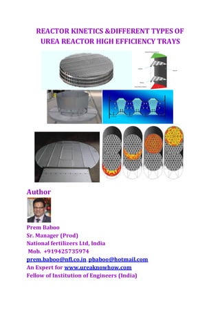
  • 1. REACTOR KINETICS &DIFFERENT TYPES OF UREA REACTOR HIGH EFFICIENCY TRAYS Author Prem Baboo Sr. Manager (Prod) National fertilizers Ltd, India Mob. +919425735974 prem.baboo@nfl.co.in ,pbaboo@hotmail.com An Expert for www.ureaknowhow.com Fellow of Institution of Engineers (India)
  • 2. PURPOSE 1. The main purpose HET to improve the redistribution of unreacted carbon dioxide inside the liquid phase rich in free ammonia. 2. To reduce the back mixing phenomenon due to density increase of carbamate and urea solution from bottom to reactor top. 3. To reduce also channelling which has a negative effect on the solution residence time. ADVANTAGES The activity contributes to environmental and social aspects and eventually to sustainable development by: Reduction of consumption of non - renewable fuel like NG, which is a step towards conserving natural resources. Reducing steam consumption which results in reduction in energy consumption. Steam is used in the strippers and varies proportionately with the urea production. Due to the improved conversion efficiency of the process (again due to improved tray design and increased number of trays), the steam utilisation in the overall manufacturing process has reduced. Hence the parameter of the specific consumption of steam to urea gives a clear indication of the energy saved. As elaborated above, the specific consumption of the steam to urea forms the critical parameter and hence the urea production and accordingly the steam consumptions are monitored. Fig.-1 A typical reactor therefore contains a gaseous phase and a liquid phase flowing in co-current flows inside a pressurized reaction chamber. Conversion of ammonia and carbon dioxide to ammonium carbonate and ultimately urea is enhanced as fig-1, i.e. to increase urea output, using tray reactors. Urea tray reactors substantially comprise a normally cylindrical shell, which
  • 3. extends substantially along a normally vertical axis, and is fitted inside with elements, i.e. trays, defined by respective metal sections shaped and/or perforated to divide the reaction chamber into compartments and form specific paths for the substances inside the reactor. The trays are normally perpendicular to the vertical axis of the reactor, and equally spaced along the axis to the full height of the reactor. The trays are very often perforated, i.e. have holes variously arranged and possibly of different shapes and/or sizes. Fluid dynamics and its influence on heat and mass transport rates in gas–liquid reactors is, in general, an important starting point for development of a process design. Improvements in the understanding of these aspects can be particularly fruitful in the case of urea reactors where the fluid-dynamic patterns are complicated by the co-current flow of two phases and the bubbling mode of the vapours. The analysis of such systems highlighted the non-optimal design of existing reactors and led to the conception of new reactor internals. Several industrial applications demonstrate the ability of the new configuration to improve reactor efficiency. Both energy-saving and production increases were obtained. This is a further demonstration that even mature technologies can be improved, leading not only to economic advantages, but also to a reduction in their environmental impact. With CO2conversion in the reactor ranging from 56 to 70%, depending on the particular technology adopted, efforts to obtain improvements have mostly been addressed to the recycle system. The efficiency of the synthesis reactor itself has been particularly under evaluated, probably following the common conviction that the optimum performance had already been achieved. Urea reactors consist of cylindrical vessels (generally 20–40 m high), having diameters from 1 to 3 m, containing, in most cases, several trays giving rise to a stage-wise structure. The aim is to reduce axial back mixing and redistribute the vapour phase. Some-times, reactors operating at high NH3/CO2 ratios and pressures, and having relatively small diameters, are used without trays. In the most widespread process configurations, the unconverted reactants are recycled to the reactor through a series of decreasing pressure stages using heat provided by steam. The higher the CO2 conversion, the smaller the amount of heat and the size of the equipment needed to reach a certain capacity. During the formation of urea, vapour and liquid are present all along the reactor, flowing co- Currently and exchanging mass and enthalpy fluxes through their interfaces. As the process is also characterized by reversible reactions, the overall behaviour is controlled by both physical and chemical equilibrium, coupled with physical and chemical kinetics. The trays are preferably designed for insertion through the manhole reactors are normally provided with, so they can also be fitted to existing reactors and/or removed and replaced. For which reason, the trays are normally made in a number of parts that fit together. The trays have various functions, and in particular: 1. Maximize the hold time of the light (faster) phase; distribute the reactants as evenly as possible along the reactor section, to prevent back-mixing’;
  • 4. 2. Enhance mixing of the gaseous- and liquid phases; and 3. Reduce bubble size' to improve diffusion of the ammonia in the carbon dioxide. Numerous urea reactor tray designs and configurations are known. The Principle of high efficiency trays:- 1. Mass transfer factor 2. Contact pattern of phase 3. Fluid dynamics factors 4. Interfacial surface area 5. Geometry of reactor vessel 6. Chemical kinetics factors 7. Temperature & pressure Generally speaking, known solutions fail to provide for thorough mixing of the light and heavy phases (both consisting of supercritical fluids) , which, because of the difference in density, tend to flow along separate preferential paths defined by the design and arrangement of the trays, and in particular by the shape, location, and size of the holes in the trays. This drawback also impairs final conversion of the reactants, thus reducing urea output. 1. The geometry of the reactor tray according to the present invention provides for thoroughly mixing the gaseous and liquid phases in a urea reactor and urea production process, and so greatly increasing urea output. 2. The reactor tray according to the present invention and the reactor as a whole are also extremely easy to produce and install. 3. Urea producers can reduce consumption and/or increase production of their plants by introducing the various revamping technologies developed The installation high efficiency trays are giving an increased production of urea and reduced steam consumption; the financial benefits are determined by the urea sales and energy prices. It has been demonstrated that the installation of high efficiency reactor trays in existing urea plant is very profitable. THE USE OF REACTION KINETICS TOIMPROVE THE CONVERSION IN VERTICAL UREAREACTORS The conversion of Carbamate into urea is a relatively slow reaction and requires heat. Non converted ammonia and carbon dioxide, passing the high-pressure carbamate condenser, supply the heat needed for this reaction. Because of the equilibrium
  • 5. reaction, the reaction is preferably done in a plug flow type of reactor. Installing a number of continuous stirred tank reactors in series can approach plug flow. Thus the urea reactor is divided into a number of compartments, mostly separated with sieve trays, and each compartment acts as a continuous stirred tank reactor. As a result plug flow is approached in such a cascade type reactor. Fig.-2(a) Fig.-2(b) To obtain a continuous stirred tank reactor, stirrers should be applied. However urea reactors are not equipped with mechanical stirrers. The driving force for mixing the liquid in the compartments of the reactor is the gas phase. The urea reactor is a so- called high-pressure bubble column. By adding the gas phase through the center of a compartment via carefully designed holes, a Torus circulation exists and thus the required mixing of the liquid in such a compartment is obtained, as fig. 2(a) the principle of such a Torus circulation exists and thus the required mixing of the liquid in such a way Compartments obtained. The principle of such a torus circulation is shown in the figure.Because the urea reaction is a relatively slow equilibrium reaction a relative large retention time in the reactor is needed to approach the maximum equilibrium level. Fig.-3, However an infinite large reactor volume is required to reach this equilibrium. For economic reasons the installed reactor volume in the designing of urea plants is such that the fraction approach to equilibrium (FAE) is 95 percent. The fraction approach to equilibrium is defined as: FAE = 100* ήC02 actual/ ή C02 equilibrium Fig.-3 Retention F.A.E ή co2
  • 6. The relation between the fraction approach to equilibrium and the retention is shown in Fig. In large-scale urea plants (> 1500 MTPD), equipped with reactors with large diameters and conventional type reactor trays, it is observed that the expected fraction approach to equilibrium is not reached resulting in a relative low reactor conversion. The consequence is that at a specified plant capacity the steam consumption on the high-pressure stripper is larger than expected. The reason for the observed relative low reactor conversion was a non-optimal mixing rate in the urea reactor compartments and, thus, these compartments did not act as an optimal continuous stirred tank reactor. The non-optimal mixing behavior in such reactors can be caused by: 1. Back mixing 2. Channeling (fig-5,a) 3. Stagnant zones Back mixing occurs when the liquid phase passes the sieve trays through the gas holes. This occurs when the height of the gas cushion below the sieve tray is small. In reactors with large diameters, when the reactor tray is not perfectly horizontal then the . gas holes are in contact with the liquid phase. This is illustrated in Fig.-4 Reactors with a relative large diameter are sensitive for stagnant zones. Stagnant zones are caused by poor mixing in the compartments and have a negative impact on the reactor conversion since the compartments will not optimally act as the required continuous stirred tank reactor. To avoid the negative effects of back mixing and channeling, Stamicarbon developed in the beginning of the 90’s the high efficiency trays as illustrated in the fig. Channeling occurs when the liquid phase is partly bypassing a compartment. In urea reactors, equipped with conventional sieve trays, the liquid is transported from the one compartment to the other compartment via the annular spacing between the tray and the reactor wall. In urea reactors with large diameters it appears that the mixing rate by
  • 7. the Torus circulation may not be large enough to avoid these channeling effects. The channeling effect is shown in Fig. Fig.-5(a) Fig-5(b) HIGH EFFICIENCY TRAYS, HET These high efficiency reactor trays are equipped with liquid risers where the liquid enters the following compartment. By staggering the liquid risers, the liquid is forced into the Torus circulation and channeling is eliminated. To avoid back mixing, the gas cushions were increased and this makes the trays less sensitive to horizontal variations of the tray. Because the conversion of carbamate into urea is an equilibrium reaction, the reaction is preferably done in a plug flow type of reactor; that is to say, one in which the flow of reaction medium is uniform and non-turbulent over the entire cross-section of the reactor interior. It is difficult to prevent turbulence and back mixing in a large unconfined body of fluid; however, an approximation to overall plug flow can be attained in a number of continuous stirred tank reactors arranged in series. Therefore the urea reactor is divided into a number of compartments, separated from one another by sieve trays, and each compartment emulates a continuously-stirred tank reactor. The driving force for mixing the liquid in the compartments of the reactor is the gas phase. By forcing the gas phase to pass through the centre of a compartment via carefully designed holes, a Torus-shaped circulation prevails and thus the required mixing of the liquid in such a compartment is obtained. However, in larger reactors non-optimal mixing behaviour has been identified and investigated. Identified causes were back mixing, channelling and stagnant zones. To address that problem, Stamicarbon has developed a new generation of high efficiency trays known as Siphon Jet Pump trays. The compartments, separated by sieve trays, are equipped with a draft tube. Inside the draft tube there is a two-phase flow of gas and liquid. The effective density of this two- phase flow is considerably lower than the liquid density on the outside of the draft tube, and the density difference further enhances liquid circulation, promoting mixing. The deflector plates in the pool reactor and pool condenser, which work on the same principle as the draft tube, have amply proved this effect. Using Siphon Jet Pump trays provides the closest approach to a continuous stirred tank reactor without necessitating
  • 8. any mechanical agitation. The mixing rate is increased significantly and the negative effects of back-mixing and channelling are avoided. The first Siphon Jet Pump trays were installed at SKW Piesteritz, and the result was so satisfactory that Siphon Jet Pumps have been installed in all three plants and are currently in operation. They have had the effect not only of making operations very smooth and raising the capacity of the existing plants, but also of reducing the HP steam requirement of the HP stripper. Amongst others, Fauji Pakistan, ABF Malaysia and Qafco Qatar have also installed iphon Jet Pumps in their Although the high efficiency trays 'improved the reactor efficiency significantly, they did not improve the mixing rate. The mixing is still reliant upon the Torus circulation. In practice it appeared to be difficult to keep the strict tolerances for the gap between the reactor tray and the reactor wall because of the no roundness of the reactor. To improve the mixing rate in the reactor compartment sand to avoid strict Mechanical tolerances, Stamicarbon recently developed a new generation of H.E.T. Known as siphon jet pumps Fig.-6 The compartments, separated by sieve trays, are equipped with a draft tube. Inside the draft tube there is a two-phase flow with the density of this two-phase flow being considerably less than the liquid density at the outside of the draft tube. By this density difference liquid circulation is enhanced further stimulating the mixing. The deflector plates in the pool reactor and pool condenser, in which the deflector plates have a similar function as the proposed draft tube, have proved these phenomena
  • 9. Because of this heavy circulation effect and thus improved mixing rate it is no longer necessary to equip the reactor trays with liquid risers. The liquid can enter the following Compartment via the annular spacing between the tray and the reactor wall in a similar fashion as the conventional Reactor trays. The strict tolerance regarding the gap between The tray and the reactor wall for the new generation HET is No longer required The first Siphon Jet Pumps were installed in one of the plants of SKW Piesteritz. Because the trays were operating very satisfactory, two other reactors of SKW Piesteritz are now also operating with Siphon Jet Pumps. In the following table the current references for Siphon Jet Pumps are presented. Table-1 Client Capacity Year in Number of New/Modified (MTPD) operation trays trays SKW Piesteritz 3 1050 2001 11 New SKW Piesteritz 1 1050 2002 11 New SKW Piesteritz 2 1050 2003 11 New Fauji Fert.Pakistan 1670 Completed in 2004 10 Modified ABF Malaysia 2250 Completed in 2004 11 New Qafco II 1400 Completed in 2005 11 New Daqing 2300 Completed in 2005 11 New Qafco III 3000 Completed 11 New The gas holes in the tray are more centered than in the conventional tray design to improve the driving force and the tray is equipped with a ring that acts as a Venturi to improve the mixing rate,as fi 8 & 9.By installing these siphon jet pumps all aspects to approach the continuous stirred tank reactor are included. The mixing rate is increased significantly and the negative effects of back mixing and channeling are avoided.
  • 10. Fig.-7 CASALE TRAYS Fig.-8 1. Inverted ‘U’ type , better mixing due to generation of smaller bubbles increasing interfacial surface area and improving the contact pattern causing higher CO2 conversion F.A.E. A- convention trays B- high eff. Trays C -Siphon jet pump
  • 11. Fig.-9 2. Small perforation at top and sloping area for vapour space and large perforation for liquid at bottom area 3. But CASALE trays suffers from corrosion due to sharp configuration Fig.-10 In combination with other Casale technologies such as the High Efficiency Trays, the Split Flow Loop/ Full Condenser configuration is applied for increasing the capacity of CO2 stripping plant with very low investment. High Efficiency reactor trays, the HP loop is drastically debottlenecked even for a large capacity increase (Up to 50% over its original design. Casale, therefore, foresaw to install the Casale Dente High Efficiency Trays in order to debottleneck the HP synthesis section.
  • 12. TABLE.-2 - Plant performance after Casale trays installation Plants Country Year Process No. of Trays CO2 conversion Increase(%points) MP Steam Consumption reduction(kg/MT) Capacity increase (%) Togliatti Azot Russia 1993 NH3 Stripping 14 6.4 300 17 Togliatti Azot Russia 1993 NH3 Stripping 14 4 200 17 Arcadian Trinidad 1994 NH3 Stripping 14 2.8 183 9 Yuman Chem(*) China 1994 CO2 Stripping 10 3.5 148 3 Agrium Can Canada 1994 CO2 Stripping 10 5 65 - Chemco Bulgaria 1995 NH3 Stripping 14 NA 170 6 CFI(**) USA 1995 CO2 Stripping 10 3.5 70 10 Agrium USA USA 1995 NH3 Stripping 10 5.3 251 9 Amonil Romania 1996 CO2 Stripping 11 5 178 8 NFCL India 1996 NH3 Stripping 14 4.5 95 3 Shriram India 1996 Total Recycle 14 6 >100 - NFL,Nangal India 2001 Montedition 14 6 110 6 Note.-(*) only 5 HET installed (**) Data after trays installation based on Casale Survey Casale has been, in the last decades, very active in revamping existing plant and has extensive experience in the design and implementation of complete plant revamping projects, including major modifications to key equipment. Casale’s plant revamp strategy has always been to develop and apply new, advanced technologies to obtain the best possible improvement in plant performance at the minimum cost; with the aim of reducing the energy consumption and/or increasing the capacity The Casale-Dente High Efficiency Trays (HET) are the most efficient trays available on the market and are also an essential element in making the Split-Flow-Loop as efficient as it is. The improved geometry of these trays has a profoundly beneficial effect on the mass transfer efficiency of NH3 and CO2 from the vapours into the liquid phase where urea is formed. The new trays are designed in such a way that: · Vapours and liquid follow separate, but adjacent cocurrent paths through the space between the trays. This guarantees stable flow of the two phases and a better approach to an even uniform flow of the two phases throughout the whole reactor. · These separated paths through the tray are chosen so that very efficient mixing takes place between vapour and liquid. Consequently there is a very high degree of both mass and heat transfer within the liquid phase is realised. · It is possible to generate vapour bubbles with a far smaller diameter than with any previous design. As a consequence, the interfacial surface, for mass and heat transfer, is increased. · There is also a much larger interfacial surface for exchange between the
  • 13. vapour bubble emulsion and clean liquid. · The relative short path length of the recirculation streams into the emulsion phase significantly decreases transfer resistances. The trays are plates corrugated into a series of parallel linear ridges and troughs. The ridges are flattened at the top and the troughs are similarly flattened at the bottom. Large perforations are provided in the trough bottoms for liquid to pass through and there are small perforations in the tops of the ridges for gases accumulating beneath them to pass This unique design produces extremely small bubbles and, as a consequence, a very high specific surface area for mass and heat transfer enhancing the highly efficient mixing between vapours and liquid mentioned above. SNAMPROGETTI (SAIPEM) SUPERCUPS TRAYS 1. The innovative M/S. Saipem Super Cups design for Urea reactor trays has been conceived and developed by Saipem with the support of Engin Soft by means of CFD(Computation Fluid dynamics) simulation. Latest super cup trays the third generation of high efficiency trays recently invented and patented by Saipem 2. Computational Fluid Dynamics (CFD) provides a qualitative (and sometimes even quantitative) prediction of fluid flows by means of mathematical modelling (partial differential equations) 3. The computer code (software) which embodies this knowledge and provides detailed instructions (algorithms) for the computer hardware which performs the actual calculations. CFD is a highly interdisciplinary research area which lies at the interface of fluid dynamics. 4. The Reactor trays that prevent back-flow of the heavier solution from the upper part downwards and favour the gas absorption in the liquid phase. 5. The support of a systematic plan of fluid-dynamic simulations gave a significant contribution to the development of the innovative design. 6. The proprietary M/S Saipem Super Cups (“New Design”) greatly increases the mixing of the liquid and gaseous phases, respectively ammonia and carbamate, and carbon dioxide, thus optimizing the product conversion rate in the reactor. The immediate benefit is the lower specific steam consumption requirement to decompose carbamate to CO2 and NH3 in downstream sections. 7. This represents a further step ahead to get closest to the theoretical equilibrium conversion in the reactor. In fact, the increase in the reaction conversion is strictly dependent on the mixing conditions of ammonia, carbamate and carbon dioxide through the reactor so that the main purpose of these innovative trays is to further improve the contacting conditions among the reagents. 8. The peculiar behaviour of the Super Cups is characterized by a triple fluid-dynamic effect – Gas Equalizer, Mixer Reactor and Gas Distributor. 9. The first effect of Super Cups is to uniformly distribute the concentration of the gaseous phase reagent on the entire section of the tray. In this way, the gas bubbles moving upward “lose the memory” of the non-uniformity of the previous reaction stage and the non-reacted CO2 can be evenly fed to each cup of the tray. Figure shows the formation of the “gas-cushion” (blue area) just below the tray externally to the cups. The cups behave as multiple confined reaction volumes in which the
  • 14. reagents - gaseous CO2 and liquid ammonia & carbamate – heavily swirl inside, thus reaching a high mixing degree. Each cup performs as a static mixer where the phases are strongly contacted. 10. In this way the Super Cups Trays do not simply behave as gas distributors – as in other commercial designs. But perform as additional active reaction stages which can be modelled as a Continuous-Stirred-Tank Reactor (“CSTR”),as fig 12. The CSTR behaviour (ideal perfect mixing) of each single tray can be clearly observed by the comparison of RTD curves for the new and standard designs. 11. The mean residence time increases by about 70% with respect to the standard design, thus strongly improving the urea formation yield. 12. The CO2 gaseous phase forming the gas-cushion below the tray can be partially streamed inside the cups to create a mixer reactor and partially distributed on the upper stage. This split range is one of the most critical design parameter since it allows the customization of the RTD curve of each reactor stage and the increase or decrease of the CSTR (perfect mixing) or PFR (plug flow) behaviour according to the composition of each stage. 13. The Super Cups Trays permit an increase in the urea reactor efficiency with consequent beneficial effects in terms of higher return on investment, lower energy consumptions and reduced environmental impact. 14. The CFD study of the traditional perforated plate vs. the innovative tray facilitated the ability to compare the fluid dynamic behaviour of several designs in terms of mixing performance of the reactants, flow patterns, pressure drops and residence time. Fig.-11
  • 16. CONCLUSIONS With the combination of skilful modelling and original design, the possibility was proven of increasing the efficiency of urea reactors, which were considered for a long time to be operating close to their optimum. This new tray design represents a significant upgrade of the urea reactors and, by consequence, of the whole plant. The net improvement of the CO2 conversion in an existing plant has, in fact, The following advantages: 1. The reduction of the energy consumption and of recycle. 2. The possibility of a sensible increase of the production with the same reactor. The development and successful design of the High Efficiency trays in the reactor was possible through a very accurate fluid dynamic simulation of the system combined with the modelling of the chemical-physical equilibriums and of the heat transfer phenomena. The most important of these consists of a sharp reduction in specific steam consumption. This feature was con-firmed by a number of test run results carried out in the field. Reductions of specific steam consumption up to 250–300 kg per ton of urea have been obtained and capacity increases up to 10–20 % . ****************************************************************************************