Chemical reactors
•Download as DOCX, PDF•
1 like•163 views

chemical reactors

Recommended
More Related Content
What's hot
What's hot (20)
Similar to Chemical reactors
Similar to Chemical reactors (20)
More from Soporte Adi Unefm Punto Fijo
More from Soporte Adi Unefm Punto Fijo (20)
Recently uploaded
Recently uploaded (20)
Chemical reactors
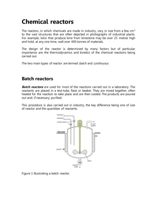
- 1. Chemical reactors The reactors, in which chemicals are made in industry, vary in size from a few cm3 to the vast structures that are often depicted in photographs of industrial plants. For example, kilns that produce lime from limestone may be over 25 metres high and hold, at any one time, well over 400 tonnes of materials. The design of the reactor is determined by many factors but of particular importance are the thermodynamics and kinetics of the chemical reactions being carried out. The two main types of reactor are termed batch and continuous. Batch reactors Batch reactors are used for most of the reactions carried out in a laboratory. The reactants are placed in a test-tube, flask or beaker. They are mixed together, often heated for the reaction to take place and are then cooled. The products are poured out and, if necessary, purified. This procedure is also carried out in industry, the key difference being one of size of reactor and the quantities of reactants. Figure 1 Illustrating a batch reactor.
- 2. Following reaction, the reactor is cleaned ready for another batch of reactants to be added. Batch reactors are usually used when a company wants to produce a range of products involving different reactants and reactor conditions. They can then use the same equipment for these reactions. Examples of processes that use batch reactors include the manufacture of colorants and margarine. Figure 2 Colorants being produced in a batch reactor. The top of the reactor is at floor level and the rest of the reactor is suspended below it. Bykindpermission of BASF. Continuous reactors An alternative to a batch process is to feed the reactants continuously into the reactor at one point, allow the reaction to take place and withdraw the products at another point. There must be an equal flow rate of reactants and products. Whilecontinuous reactors are rarely used in the laboratory, a water-softener can beregarded as an example of a continuous process. Hard water from the mains is passed through a tube containing an ion-exchange resin. Reaction occurs down the tube and soft water pours out at the exit.
- 3. Figure 3 Illustrating a continuous reactor. Continuous reactors are normally installed when large quantities of a chemical are being produced. It is important that the reactor can operate for several months without a shutdown. The residence time in the reactor is controlled by the feed rate of reactants to the reactor. For example, if a reactor has a volume of 20 m3 and the feed rate of reactants is 40 m3 h-1 the residence time is 20 m3 /40 m3 h-1 = 0.5 h. It is simple to control accurately the flow rate of reactants. The volume is fixed and therefore the residence time in the reactor is also well controlled. The product tends to be of a more consistent quality from a continuous reactor because the reaction parameters (e.g. residence time, temperature and pressure) are better controlled than in batch operations. They also produce less waste and require much lower storage of both raw materials and products resulting in a more efficient operation. Capital costs per tonne of product produced are consequently lower. The main disadvantage is their lack of flexibility as once the reactor has been built it is only in rare cases that it can be used to perform a different chemical reaction. Types of continuous reactors Industry uses several types of continuous reactors. (a) Tubular reactors In a tubular reactor, fluids (gases and/or liquids) flow through it at high velocities. As the reactants flow, for example along a heated pipe, they are converted to products (Figure 4). At these high velocities, the products are unable to diffuse back and there is little or no back mixing. The conditions are referred to as plug flow. This reduces the occurrence of side reactions and increases the yield of the desired product.
- 4. With a constant flow rate, the conditions at any one point remain constant with time and changes in time of the reaction are measured in terms of the position along the length of the tube. The reaction rate is faster at the pipe inlet because the concentration of reactants is at its highest and the reaction rate reduces as the reactants flow through the pipe due to the decrease in concentration of the reactant. Figure 4 A tubular reactor used in the production of methyl 2- methylpropenoate. The reactor is heated by high pressure steam which has a temperature of 470 K and is fed into the reactor at point 1 and leaves the reactor at point 2. Thereactantsflowthroughthetubes. Tubular reactors are used, for example, in the steam cracking of ethane, propane and butane and naphtha to produce alkenes. (b) Fixed bed reactors A heterogeneous catalyst is used frequently in industry where gases flow through a solid catalyst (which is often in the form of small pellets to increase the surface area). It is often described as a fixed bed of catalyst (Figure 5). Among the examples of their use are the manufacture of sulfuric acid (the Contact Process, with vanadium(V) oxide as catalyst), the manufacure of nitric acid and the manufacture of ammonia (the Haber Process, with iron as the catalyst). Figure 5 Illustrating a fixed bed reactor. A further example of a fixed bed reactor is in catalytic reforming of naphtha to
- 5. produce branched chain alkanes, cycloalkanes and aromatic hydrocarbons using usually platinum or a platinum-rhenium alloy on an alumina support. (c) Fluid bed reactors A fluid bed reactor is sometimes used whereby the catalyst particles, which are very fine, sit on a distributor plate. When the gaseous reactants pass through the distributor plate, the particles are carried with the gases forming a fluid (Figure 6). This ensures very good mixing of the reactants with the catalyst, with very high contact between the gaseous molecules and the catalyst and a good heat transfer. This results in a rapid reaction and a uniform mixture, reducing the variability of the process conditions. One example of the use of fluid bed reactors is in the oxychlorination of ethene to chloroethene (vinyl chloride), the feedstock for the polymer poly(chloroethene) (PVC). The catalyst is copper(II) chloride and potassium chloride deposited on the surface of alumina. This support is so fine, it acts as a fluid when gases pass through it. Figure 6 A diagram to illustrate a fluid bed reactor. On the left hand side, the particles are at rest. On the right hand side, the particles are now acting as a fluid, as the gaseous reactants pass through the solid.