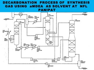
This document discusses the aMDEA process for removing carbon dioxide from process gas. It begins with an introduction and table of contents, then covers the need for CO2 removal, desirable solvent properties, commercially available processes, differences between physical and chemical absorption, selection criteria for processes, and an overview of the aMDEA process including constituents and reactions. It also discusses why the Rectisol process is not suitable, favorable absorption and regeneration parameters, common problems encountered, handling precautions, process interlocks, and problems and mistakes to avoid.
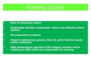
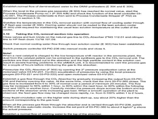
Purpose
Key to good performance
Problem Areas
Catalysts, heat shields and plant up-rates
Burner Guns
Development of High Intensity Ring Burner
Case Studies
Conclusions
VULCAN Series VSG-Z101 Primary Reforming
Initial Catalyst Reduction
Activating (reducing) the catalyst involves changing the nickel oxide to nickel, represented by:
NiO + H2 <==========> Ni + H2O
Natural gas is typically used as the hydrogen source. When it is, the catalyst reduction and putting the reformer on-line are accompanied in the same step.
Introduction High temperature shift Catalysts
Low temperature shift catalysts
Catalyst storage, handling, charging and discharging
Health and safety precautions
Reduction and start-up of high temperature shift catalysts
Operation of high temperature shift catalysts
Reduction and start-up of low temperature shift catalysts
Operation of low temperature shift catalysts
Look at two main types
Explain mechanisms
Explain prevention of cracking
Three main types
1 Carbon cracking
2 Boudouard carbon formation
3 CO reduction
Equilibrium Effects
- Methane Steam
- Water Gas Shift
Relationship of Kp to Temperature
Relationship of WGS Kp to Temperature
Effect of Temperature on Methane Slip
Approach to Equilibrium
Reaction Path and Equilibrium
Effect of Pressure Increase
Operating Parameters
- Pressure
- Temperature
- Feed Rate
- Steam to Carbon
Effect of Exit Temperature Spread
Useful Tools
Calculating ATM
Most modern ammonia processes are based on steam-reforming of natural gas or naphtha.
The 3 main technology suppliers are Uhde (Uhde/JM Partnership), Topsoe & KBR.
The process steps are very similar in all cases.
Other suppliers are Linde (LAC) & Ammonia Casale.
This is great Presentation with 3D effects which is all about production of ammonia from natural gas.
I am damn sure you will be getting everything here searching for.
its better to download it and then run in powerpoint 2013.
Amine Gas Treating Unit - Best Practices - Troubleshooting Guide Gerard B. Hawkins
Amine Gas Treating Unit Best Practices - Troubleshooting Guide for H2S/CO2 Amine Systems
Contents
Process Capabilities for gas treating process
Typical Amine Treating
Typical Amine System Improvements
Primary Equipment Overview
Inlet Gas Knockout
Absorber
Three Phase Flash Tank
Lean/Rich Heat Exchanger
Regenerator
Filtration
Amine Reclaimer
Operating Difficulties Overview
Foaming
Failure to Meet Gas Specification
Solvent Losses
Corrosion
Typical Amine System Improvements
Degradation of Amines and Alkanolamines during Sour Gas Treating
APPENDIX
Best Practices - Troubleshooting Guide
Calculation of an Ammonia Plant Energy Consumption: Gerard B. Hawkins
Calculation of an Ammonia Plant Energy Consumption:
Case Study: #06023300
Plant Note Book Series: PNBS-0602
CONTENTS
0 SCOPE
1 CALCULATION OF NATURAL GAS PROCESS FEED CONSUMPTION
2 CALCULATION OF NATURAL GAS PROCESS FUEL CONSUMPTION
3 CALCULATION OF NATURAL GAS CONSUMPTION FOR PILOT BURNERS OF FLARES
4 CALCULATION OF DEMIN. WATER FROM DEMIN. UNIT
5 CALCULATION OF DEMIN. WATER TO PACKAGE BOILERS
6 CALCULATION OF MP STEAM EXPORT
7 CALCULATION OF LP STEAM IMPORT
8 DETERMINATION OF ELECTRIC POWER CONSUMPTION
9 DETERMINATION OF THE TOTAL ENERGY CONSUMPTION OF THE AMMONIA PLANT ISBL
10 ADJUSTMENT OF ELECTRIC POWER CONSUMPTION FOR TEST RUN CONDITIONS
11 CALCULATION OF AMMONIA SHARE IN MP STEAM CONSUMPTION IN UTILITIES
12 CALCULATION OF AMMONIA SHARE IN ELECTRIC POWER CONSUMPTION IN UTILITIES
13 DETERMINATION OF THE TOTAL ENERGY CONSUMPTION OF THE AMMONIA PLANT OSBL
14 DETERMINATION OF THE TOTAL ENERGY CONSUMPTION OF THE AMMONIA PLANT
Pressure Relief Systems Vol 2
Causes of Relief Situations
This Volume 2 is a guide to the qualitative identification of common causes of overpressure in process equipment. It cannot be exhaustive; the process engineer and relief systems team should look for any credible situation in addition to those given in this Part which could lead to a need for pressure relief (a relief situation).
Introduction and Theoretical Aspects
Catalyst Reduction and Start-up
Normal Operation and Troubleshooting
Shutdown and Catalyst Discharge
Nickel Carbonyl Hazard
Modern Methanation Catalyst Requirements
High Temperature Shift Catalyst Reduction ProcedureGerard B. Hawkins
High Temperature Shift Catalyst Reduction Procedure
The catalyst, as supplied, is Fe2O3. This reduces to the active form, Fe3O4, in the presence of hydrogen when process gas is admitted to the reactor.
1. The mildly exothermic reactions are:
3 Fe2O3 + H2 ========= 2 Fe3O4 + H2O
3 Fe2O3 + CO ========= 2 Fe3O4 + CO2
Natural Gas (from a natural reservoir or associated to a crude production) can contain acid gas (H2S and/or CO2)..
The Gas Sweetening Process aims to remove part or all of the acid gas.
In the plant, ammonia is produced from synthesis gas containing hydrogen and nitrogen in the ratio of approximately 3:1. Besides these components, the synthesis gas contains inert gases such as argon and methane to a limited extent. The source of H2 is demineralized water and the hydrocarbons in the natural gas. The source of N2 is the atmospheric air. The source of CO2 is the hydrocarbons in the natural gas feed. Product ammonia and CO2 is sent to urea plant. The present article intended the description of ammonia plant for natural gas based plants and the possible material balance of some section.
In the plant, ammonia is produced from synthesis gas containing hydrogen and nitrogen in the
ratio of approximately 3:1. Besides these components, the synthesis gas contains inert gases such
as argon and methane to a limited extent. The source of H2 is demineralized water and the
hydrocarbons in the natural gas. The source of N2 is the atmospheric air. The source of CO2 is
the hydrocarbons in the natural gas feed. Product ammonia and CO2 is sent to urea plant. The
present article intended the description of ammonia plant for natural gas based plants and the
possible material balance of some section
Event Management System Vb Net Project Report.pdfKamal Acharya
In present era, the scopes of information technology growing with a very fast .We do not see any are untouched from this industry. The scope of information technology has become wider includes: Business and industry. Household Business, Communication, Education, Entertainment, Science, Medicine, Engineering, Distance Learning, Weather Forecasting. Carrier Searching and so on.
My project named “Event Management System” is software that store and maintained all events coordinated in college. It also helpful to print related reports. My project will help to record the events coordinated by faculties with their Name, Event subject, date & details in an efficient & effective ways.
In my system we have to make a system by which a user can record all events coordinated by a particular faculty. In our proposed system some more featured are added which differs it from the existing system such as security.
Cosmetic shop management system project report.pdfKamal Acharya
Buying new cosmetic products is difficult. It can even be scary for those who have sensitive skin and are prone to skin trouble. The information needed to alleviate this problem is on the back of each product, but it's thought to interpret those ingredient lists unless you have a background in chemistry.
Instead of buying and hoping for the best, we can use data science to help us predict which products may be good fits for us. It includes various function programs to do the above mentioned tasks.
Data file handling has been effectively used in the program.
The automated cosmetic shop management system should deal with the automation of general workflow and administration process of the shop. The main processes of the system focus on customer's request where the system is able to search the most appropriate products and deliver it to the customers. It should help the employees to quickly identify the list of cosmetic product that have reached the minimum quantity and also keep a track of expired date for each cosmetic product. It should help the employees to find the rack number in which the product is placed.It is also Faster and more efficient way.
Vaccine management system project report documentation..pdfKamal Acharya
The Division of Vaccine and Immunization is facing increasing difficulty monitoring vaccines and other commodities distribution once they have been distributed from the national stores. With the introduction of new vaccines, more challenges have been anticipated with this additions posing serious threat to the already over strained vaccine supply chain system in Kenya.
TECHNICAL TRAINING MANUAL GENERAL FAMILIARIZATION COURSEDuvanRamosGarzon1
AIRCRAFT GENERAL
The Single Aisle is the most advanced family aircraft in service today, with fly-by-wire flight controls.
The A318, A319, A320 and A321 are twin-engine subsonic medium range aircraft.
The family offers a choice of engines
CFD Simulation of By-pass Flow in a HRSG module by R&R Consult.pptxR&R Consult
CFD analysis is incredibly effective at solving mysteries and improving the performance of complex systems!
Here's a great example: At a large natural gas-fired power plant, where they use waste heat to generate steam and energy, they were puzzled that their boiler wasn't producing as much steam as expected.
R&R and Tetra Engineering Group Inc. were asked to solve the issue with reduced steam production.
An inspection had shown that a significant amount of hot flue gas was bypassing the boiler tubes, where the heat was supposed to be transferred.
R&R Consult conducted a CFD analysis, which revealed that 6.3% of the flue gas was bypassing the boiler tubes without transferring heat. The analysis also showed that the flue gas was instead being directed along the sides of the boiler and between the modules that were supposed to capture the heat. This was the cause of the reduced performance.
Based on our results, Tetra Engineering installed covering plates to reduce the bypass flow. This improved the boiler's performance and increased electricity production.
It is always satisfying when we can help solve complex challenges like this. Do your systems also need a check-up or optimization? Give us a call!
Work done in cooperation with James Malloy and David Moelling from Tetra Engineering.
More examples of our work https://www.r-r-consult.dk/en/cases-en/
Automobile Management System Project Report.pdfKamal Acharya
The proposed project is developed to manage the automobile in the automobile dealer company. The main module in this project is login, automobile management, customer management, sales, complaints and reports. The first module is the login. The automobile showroom owner should login to the project for usage. The username and password are verified and if it is correct, next form opens. If the username and password are not correct, it shows the error message.
When a customer search for a automobile, if the automobile is available, they will be taken to a page that shows the details of the automobile including automobile name, automobile ID, quantity, price etc. “Automobile Management System” is useful for maintaining automobiles, customers effectively and hence helps for establishing good relation between customer and automobile organization. It contains various customized modules for effectively maintaining automobiles and stock information accurately and safely.
When the automobile is sold to the customer, stock will be reduced automatically. When a new purchase is made, stock will be increased automatically. While selecting automobiles for sale, the proposed software will automatically check for total number of available stock of that particular item, if the total stock of that particular item is less than 5, software will notify the user to purchase the particular item.
Also when the user tries to sale items which are not in stock, the system will prompt the user that the stock is not enough. Customers of this system can search for a automobile; can purchase a automobile easily by selecting fast. On the other hand the stock of automobiles can be maintained perfectly by the automobile shop manager overcoming the drawbacks of existing system.
Sachpazis:Terzaghi Bearing Capacity Estimation in simple terms with Calculati...Dr.Costas Sachpazis
Terzaghi's soil bearing capacity theory, developed by Karl Terzaghi, is a fundamental principle in geotechnical engineering used to determine the bearing capacity of shallow foundations. This theory provides a method to calculate the ultimate bearing capacity of soil, which is the maximum load per unit area that the soil can support without undergoing shear failure. The Calculation HTML Code included.
Forklift Classes Overview by Intella PartsIntella Parts
Discover the different forklift classes and their specific applications. Learn how to choose the right forklift for your needs to ensure safety, efficiency, and compliance in your operations.
For more technical information, visit our website https://intellaparts.com
Hybrid optimization of pumped hydro system and solar- Engr. Abdul-Azeez.pdffxintegritypublishin
Advancements in technology unveil a myriad of electrical and electronic breakthroughs geared towards efficiently harnessing limited resources to meet human energy demands. The optimization of hybrid solar PV panels and pumped hydro energy supply systems plays a pivotal role in utilizing natural resources effectively. This initiative not only benefits humanity but also fosters environmental sustainability. The study investigated the design optimization of these hybrid systems, focusing on understanding solar radiation patterns, identifying geographical influences on solar radiation, formulating a mathematical model for system optimization, and determining the optimal configuration of PV panels and pumped hydro storage. Through a comparative analysis approach and eight weeks of data collection, the study addressed key research questions related to solar radiation patterns and optimal system design. The findings highlighted regions with heightened solar radiation levels, showcasing substantial potential for power generation and emphasizing the system's efficiency. Optimizing system design significantly boosted power generation, promoted renewable energy utilization, and enhanced energy storage capacity. The study underscored the benefits of optimizing hybrid solar PV panels and pumped hydro energy supply systems for sustainable energy usage. Optimizing the design of solar PV panels and pumped hydro energy supply systems as examined across diverse climatic conditions in a developing country, not only enhances power generation but also improves the integration of renewable energy sources and boosts energy storage capacities, particularly beneficial for less economically prosperous regions. Additionally, the study provides valuable insights for advancing energy research in economically viable areas. Recommendations included conducting site-specific assessments, utilizing advanced modeling tools, implementing regular maintenance protocols, and enhancing communication among system components.
2. CONTENTS
1. Need of Carbon Dioxide Removal from synthesis Gas
2. Various processes for Carbon Dioxide Removal
3. Desirable properties of Solvent for CO2 removal
4. Commercially available processes for CO2 removal
5. Difference between physical & chemical absorption
6. Selection criteria of various CO2 removal processes
7. aMDEA process & various constituents & reactions involved
8. Why Rectisol process not possible for CO2 removal in new plant
9. Favorable parameters for absorption & regeneration of aMDEA
& monitoring of parameters in absorption & regeneration.
10. Problems encountered with aMDEA process.
11. Various handling precautions associated with aMDEA solution.
12. Various Process Interlocks involved
13. Common Problems & mistakes
3. NEED OF CARBON DIOXIDE REMOVAL
(1) Removed CO2 is utilized in Urea formation as
a raw
material for UREA plant
(2) CO2 formed in reforming section, are not tolerable in
Ammonia Synthesis Loop. CO2 under high
temperature and pressure oxidizes the iron catalyst
in synthesis reactor which ultimately results in
temporary poisoning of catalyst as described by
following reaction
CO2 + 4H2 ⇌ CH4 + 2H2O
2Fe + 3H2O ⇌ Fe2O3 + 3H2
4. (3) CO2 reacts with the ammonia in
synthesis gas loop to form solid
deposits of ammonium carbamate
results in the corrosion .
(4) Also, Carbon Dioxide slips from the
Decarbonation unit results in the
consumption of expensive Hydrogen in
the methanation section.
5. DESIRABLE PROPERTIES OF SOLVENT FOR
REMOVAL OF CO2:-
i. HIGH CO2 SOLUBILITY
ii. HIGHLY SELECTIVE IN NATURE
iii. LOW VISCOSITY
iv. HIGH THERMAL STABILITY
v. NON CORROSIVE IN NATURE
vi. LOW VAPOUR PR UNDER OPERATING TEMP
vii. BIODEGRADEABLE, NON TOXIC & ENVOIRNMENT
FRIENDLY
viii. EASILY AVAILABLE & LOW COST
6. Commercially used Absorption ProcessesCommercially used Absorption Processes
1). Physical Absorption Process
2). Chemical Absorption Process
3). Combination of Physical & Chemical Absorption
Process
1). Physical Absorption Process
2). Chemical Absorption Process
3). Combination of Physical & Chemical Absorption
Process
Various Physical Absorption ProcessesVarious Physical Absorption Processes
Rectisol Process (Methanol as solvent ) Lurgi
Purisol Process( N Methyl – 2 Pyrrolidone as solvent )
Fluor Solvent ( Propylene carbonate as solvent ) Fluor
Selexol Process (Polypropylene Glycol of Dimethylether as
solvent) UOP Process Licensor
7. Various Hot Potassium Carbonate Solution based processes
1). Benefield process
2). Gimmarco Vetrocoke Process
3). MEA(Mono Ethanol Amine) Process
Chemical Absorption ProcessesChemical Absorption Processes
Mixed Chemical /Physical Absorption ProcessesMixed Chemical /Physical Absorption Processes
1). aMDEA(activated Methyl Diethanol Amine) Process
2). DIPA ( Diisopropanol amine )
9. Selection Criteria of CO2 removal process
depends on the following factors:
Type of feedstock used and choice of process
route selected for raw gas generation.
Amount of CO2 recovery and purity desired.
High energy consuming Ammonia plant based on
Partial Oxidation of Fuel oil or Coal gasification
employ physical process- Rectisol where CO2
partial pressure in Reformed gas is compartively
high.
10. Ammonia plant based on Natural gas Steam
Reforming route involving low partial pressure
of Carbon dioxide adopts mostly either a
Chemical Absorption Process like Benfield
Process/ GV process/ Hybrid Physio-Chemical
Process-a-MDEA.
11. aMDEA at glance
aMDEA solution in CO2 absorption process at NFL Panipat
Absorbing media.- MDEA (METHYL DIETHANOL AMINE) Tertiary
Amine
MDEA is clear, water-white, hygroscopic liquid with an ammonical odor.
Typical Physical Properties
Boiling Range, o
C 247
Flash point, PMCC, °C (°F) 116 (240)
Freezing Point, o
C (o
F) -21 (-5.8)
Specific gravity, 20/20oC 1.0431
Vapor pressure, 20oC, mm Hg <0.01
Viscosity, cSt, 100oF 36.8
Water solubility Complete
12. ACTIVATOR : Piperazine acts as a activator/promoter with MDEA solution
Synonyms: Piperazine Anhydrous,
Diethylenediamine
Molecular Formula: C4H10N2
Formula Weight: 86.13
Boiling point 1460
C
Flash point 820
C
Purpose of use of Piperazine along with MDEA : The
rate of
the reaction can be increased by using promoters,
without diminishing the MDEA advantages. So it
increases the mass transfer rate of CO2 from gas to
liquid phase.ROLE OF PROMOTER IN INCREASING RATE OF REACTION
CO2 + promoter = intermediate
Intermediate + OH-
= promoter + HCO
_
3
13. aMDEA process at NFL Panipat
Activated MDEA process for CO2 removal is a physical/chemical
absorption process. It behaves as a physical absorption process
at higher partial pressure of CO2 and as a chemical absorption
process at low CO2 partial pressure.
The main constituents of aMDEA solution
aMDEA 34 wt%
Piperazine 6 wt%
Water 60 wt%
14.
15.
16. CHEMICAL
CO2 LOADING CAPACITY OF SOLVENTS
aMDEA
PHYSICAL
CO2-LOADING,
m3
/m3
0
20
40
80
60
2 4 6 8 10 12
CO2 PARTIAL
PRESSURE, BAR
17. DIFFERENT CO2 REMOVAL PROCESSES
PROCESS T
0
C
P
Kg/cm2
g
SOLVENT CO2
SLIP
ppm
ENERGY
REQIRD.
Kcal/Nm3
CO2
RECTISOL
MEA
BENFIELD
GV
aMDEA
- 70
30-60
70-115
60-120
750
C
44
20
27-28
27-28
27 - 28
METHANOL
MONOETHANOL
AMINE
K2CO3
DEA
V2O5
K2CO3
GLYCINE
DEA
V2O5
aMDEA
2
500
1000-
1200
500
500
2700
2245
795
612
430-640
18. Benefits of using aMDEA solution for CO2 absorption from
Synthesis Gas
1. Higher CO2 removal rate in activated MDEA process as
process involves low partial pressure of Carbon
Dioxide.
2. Lower energy requirement.
3. No requirement of refrigerant as in case of Rectisol
Process.
4. Lower MDEA make up requirement due to its low
volatility.
5. MDEA (Methyl diethanol amine) is environment friendly
and biodegradable chemical.
6. MDEA is non-corrosive. Hence MDEA system does not
require any corrosion inhibitor
19. aMDEA REACTION FOR CO2 ABSORPTION
1) CO2 (gas) CO2 (sol’n)
Fast
2) CO2 (sol’n) + H2O H2CO3 (sol’n)
Slow
3) H2CO3 (sol’n) +R3N R3NH +
(sol’n) + HCO3-
(sol’n) Fast
So, overall reaction for tertiary amine is described
below :
CO2 (gas) + H2O + R3N(sol’n) R3NH+
(sol’n) +
HCO3- (sol’n)
R’(NH)2 + 2CO2 R’(NHCOO)2
The activator PZ may react with CO2 in liquid lm to form an intermediate
R’(NHCOO)2 + 2H2O R’(NH
+
2 ) + 2HCO3
-
Using Piperazine as an activator
Tertiary Amine MDEA reactions
(R3NH)+
+ (HCO3
)-
+ Heat → R3N + CO2 + H2 O
Tertiary Amine Regeneration reaction
24. WHY Rectisol Process could not used with new Set up of Plant???
As in new plant CO2 generation is low due to the low C/H ratio
as result the partial pressure of CO2 in the process gas is low
which result in the ineffectiveness of the rectisol process which
is purely based on physical absorption.
There is not huge surplus Nitrogen availability due to properly
regenerate the Methanol solvent.
No need of set up of extra refrigeration unit
Lesser make up rate of solvent required due low volatility of solvent
25. Bulk CO2 is absorbed in the bottom beds of the column
Only refining of CO2 takes place in the top two beds
26. aMDEA THEORY
a. FAVOURABLE PARAMETERS FOR ABSORPTION
1. HIGH PRESSURE
2. BETTER ACTIVATOR ( PIPERAZINE)
3. LOWEST OPTIMUM TEMPERATURE
4. OPTIMUM SPLIT STREAM TEMP
5. IMPROVED PACKED BEDS AND INTERNALS
b. FAVOURABLE PARAMETERS FOR REGENERATION
1. LOW PRESSURE
2. PROPER DISTRIBUTION OF RICH SOLN
3. IMPROVED PACKED BED AND INTERNALS
4. REGN. STREAM FLOW / TEMP OPTIMUM
27. Absorber parameters to be kept
under control:
CO2 content in purified gas (main parameter).
Circulation pumps flow rate.
Solution temperature.
Pressure drop.
Operating pressure.
Solution composition.
Temperature profile of the CO2 absorber.
Foaming tendency of the solution
28. Stripper parameters to be kept
under control:
Top Temperature of the stripper.
Bottom temperature of the stripper.
Pressure drop across the stripper.
Operating pressure of the stripper.
Reboiler duty of the stripper
29. MAIN PROBLEMS ENCOUNTERED WITH
HANDLING
aMDEA SOLUTION PROCESS FOR CO2
CAPTURING
Formation of Heat Stable Salts.
Foaming of the aMDEA solution
FORMATION OF HEAT STABLE SALTS WITH aMDEA
MDEA is the most forgiving amine from a corrosion standpoint,
as compared to other amines i.e. MEA & DEA it does not leads
to the formation of bicarbonates which are mostly resulted in
the lower of PH value of solution leading to corrosion.
Regardless of amine type for the CO2 capture process,
the formation of heat stable salts (HSSs) in amine solutions
has long been a problem.
30. HSSs are formed in the presence of acids which are substantially
stronger than CO2 . These acids are formed from amine
degradation product which are mostly resulted from the
overheating in case of CO2 stripper or from the impurities present
in synthesis gas.
For example, if formic acid is produced, it will react with MDEA to
form a formate HSS
Absorber reaction :
R3N + HO2CH → (R3
NH)+
+ (O2CH)-
[amine plus acid → salt]
Regenerator reactions :
(R3NH)+
+ (O2CH)-
+ Heat → No Change
Thus HSSs typically promote corrosion in the systems because
they lower the pH and increase the conductivity of amine
solutions. This can decrease the efficiency of CO2 capture
because of the irreversible reaction with the amine.
31. Remedy to remove Heat Stable Salts & monitoring the process:
Installation of activated carbon filter for the removal of the
degraded amine products and organic acids from lean solution
split stream.
Periodical inspection of corrosion in the line by the installation of
Corrosion coupons at the critical positions.
Periodical sampling of aMDEA solutions
Remedy to remove Heat Stable Salts & monitoring the process:
Installation of activated carbon filter for the removal of the
degraded amine products and organic acids from lean solution
split stream.
Periodical inspection of corrosion in the line by the installation of
Corrosion coupons at the critical positions.
Periodical sampling of aMDEA solutions
32.
33. PRECAUTIONS IN HANDLING aMDEA SOLVENT
Use Demineralized water for diluting aMDEA premix and
presence of oxygen in make up water severely increase the
corrosivity of aMDEA. Make up water having < 10 wppm is
Recommended for use.
Make up water should have lower chloride level as higher
levels leads to higher localized corrosion. Also, aMDEA is
A chloride free product only chance of getting high chloride
content is from make up water. Max. recommended chloride
content in make up water is 2ppm by wt.
Annual solvent losses are 5% to 10% of aMDEA premix
inventory, which are mainly due to mechanical reasons such
as pump leakage, filter replacement and cleaning liquid
entrainment in off gas stream.
Another major area of concern is loss of activator as it is
more volatile than MDEA which is balanced by enriched
aMDEA make up solution.
34. aMDEA premix can be stored as delivered drum in a warehouse or
in storage tanks which are necessarily blanketed with Nitrogen gas
To avoid the contact with air which can turn the solvent colour
from Light yellow to brownish, due to the formation of degradation
products in ppm range.
Another important reason behind Nitrogen blanketing of solution
storage tank is to prevent explosion due to the release of residual
Hydrogen and other flammable gases from the solution when it is
transferred from system to the storage tank. So, do not transfer the
Rich solution to the storage tank.
Another important thing is maintain the proper temperature of
aMDEA premix in the solution storage tank as too low temperature
Leads to the precipitation of the activator.
Enriched aMDEA composed of 40% MDEA, 40% activator, 20% H2O
Below 200
C activator start to precipatate and solidifies at minus
10O
C
35. PROBLEMS FACED DURING OPERATIONS OF C02 REMOVAL SECTION
1. CO2 stripper Top Temperature fluctuation which should be maintained in range (940
C to 960
C)
Reason behind CO2 stripper Top Temperature fluctuations
1. During Level make in B301
2. Plant Load reduction & increase
3. Increase or decrease of the Carbon number of the NG feed as its composition
changes
Consequence of High CO2 stripper Top Temperature
High Temperature results from high heat duty of Stripper reboiler E302 which ultimately
overheating of aMDEA solution resulting in its degradation leads to the formation of heat stable
salts(HSS) which finally resulting in increase in the foaming tendency and lessens the CO2
Loading capacity of the solution
Consequence of Low CO2 stripper Top Temperature
Low temprature results in the insufficient stripping of semilean solution which
will results in the Lowering of the CO2 Loading capacity of the solution
36. 2. High CO2 slip in the outlet of CO2 absorber F302
Possible reasons behind high CO2 slip in the outlet of CO2 absorber
1.Insufficient Semi Lean & Lean solution circulation rates
2. Higher %CO2 in the inlet gas to the absorber due to high plant load or high content of
heavier components in the NG feed.
3. Weak concentration of the aMDEA solution.
4. Low Temperature operation of the CO2 strippper Column.
5. Low Pressure operation of the CO2 absorber Column
2. High CO2 slip in the outlet of CO2 absorber F302
Possible reasons behind high CO2 slip in the outlet of CO2 absorber
1.Insufficient Semi Lean & Lean solution circulation rates
2. Higher %CO2 in the inlet gas to the absorber due to high plant load or high content of
heavier components in the NG feed.
3. Weak concentration of the aMDEA solution.
4. Low Temperature operation of the CO2 strippper Column.
5. Low Pressure operation of the CO2 absorber Column
37. FOAMING CAUSES
Dust of activated carbon
Suspended metallic compounds, which may disturb surface
tension
Decomposition products
Organic substances, grease, lube oil, paint bitumen epoxy
resins. Sulphides
High temperature operation CO2 stripper reboiler which
resulting in HSS which are responsible for foaming
38. FOAMING INDICATORS
High PDI across the beds in the Absorber and regenerator.
High CO2 slip in the outlet process gas fro the absorber.
Amine solution carry over with the product gas from the
absorber.
Solution Hold up in bed packing.
High instability in the levels of the absorber.
REMEDY FOR CHECKING FOAMING PROBLEM
Provide Cartridge type of filter in U/S & D/S of activated
carbon filter bed having filtration pore size of 10 micron.
Use antifoaming solution and ensure its continuous dosing of
antifoaming solution.
61. Some Common Mistake which can be possible in the CO2 removal section
High aMDEA circulation rate during plant load reduction which will result in the
Unnecessary demand heating steam in the CO2 stripper reboiler E302 and also
Leads to high power consumption on the account of high circulation rate.
Lower CO2 stripper top temperature which results in the high CO2 slip
High flow of the heating steam in the CO2 stripper reboiler E302 without
optimising the temperature of steam flow through TIC 316 to make the
availability of the Saturated steam in the CO2 stripper reboiler E302 during
start up.
Not maintaining Pressure in the HP Flash drum during the shutdown/tripping/
Startup of the Plant by not opening nitrogen on time leads to the difficulty in the
Transfer of level to LP Flash drum.