Downloaded 383 times


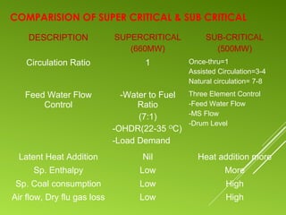


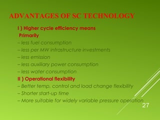
![29
INCREASE OF CYCLE EFFICIENCY DUE TO
STEAM PARAMETERS
300
241
175 538 / 538
538 / 566
566 / 566
580 / 600
600 / 620
6,77
5,79
3,74
5,74
4,81
2,76
4,26
3,44
1,47
3,37
2,64
0,75
2,42
1,78
0
0
1
2
3
4
5
6
7
8
9
10
HP / RH outlet temperature [deg. C]Pressure [bar]
Increase of efficiency [%]](https://image.slidesharecdn.com/super-criticalboiler-160309140412/85/Super-critical-boiler-29-320.jpg)


The document discusses the principles and advantages of supercritical boiler technology, highlighting its operational efficiency, lower fuel consumption, and reduced emissions compared to subcritical systems. Key differences between supercritical and subcritical cycles, such as water circulation, material requirements, and heat transfer mechanisms are outlined. Additionally, it addresses challenges in supercritical technology, such as stringent water chemistry control and maintenance difficulties.


