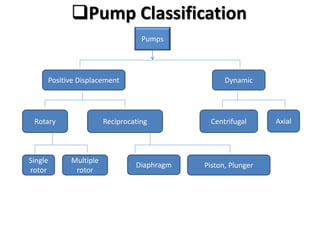
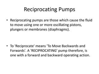
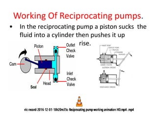
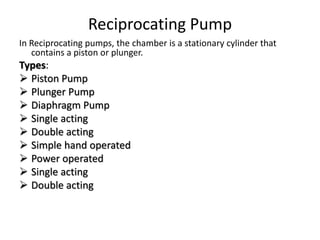
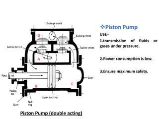
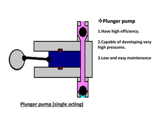
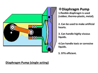
PUMPS
PRESENTED BY :
Rizwan Ali
2014-UET-KIT-Mech-11
Fahad Rafiq
2014-UET-KIT-Mech-21
D.R AQ Khan Instetute Mianwali
Subject Code : 351
Name Of Subject : Fluid Flow Process
Name of Unit : Pumps
Topic : Reciprocating pumps
Defination
• Water pumps are devices designed to convert
mechanical energy to hydraulic energy.
• They are used to move water from lower
points to higher points with a required
discharge and pressure head.
• This chapter will deal with the basic hydraulic
concepts of water pumps.
Pump Classification
Pumps
Positive Displacement Dynamic
Rotary Reciprocating Centrifugal Axial
Single
rotor
Multiple
rotor
Diaphragm Piston, Plunger
Pump Classification
• Turbo-hydraulic (kinetic) pumps
Centrifugal pumps (radial-flow pumps)
Propeller pumps (axial-flow pumps)
Jet pumps (mixed-flow pumps)
• Positive-displacement pumps
Screw pumps
Reciprocating pumps
Positive Displacement Pump
Positive Displacement pumps apply pressure directly to the
liquid by a reciprocating piston, or by rotating members.
Uses:
1.can handle shear sensitive liquid.
2.Use for high pressure application.
3.Use for variable viscosity applications.
Types:
Reciprocating pump
Rotary pump
Positive Displacement
Characteristic
Actual
Theoretical
Flow Q m3/h
Total
Head
H m
Reciprocating Pumps
• Reciprocating pumps are those which cause the fluid
to move using one or more oscillating pistons,
plungers or membranes (diaphragms).
• To 'Reciprocate' means 'To Move Backwards and
Forwards'. A 'RECIPROCATING' pump therefore, is
one with a forward and backward operating action.
Working Of Reciprocating pumps.
• In the reciprocating pump a piston sucks the
fluid into a cylinder then pushes it up
causing the water to rise.
Type & Construction features of
reciprocating Pump:--
1. Position - Vertical - Horizontal
2. Purpose - Metering Pump - Power Pump
3. Piston or Plunger acting : Single acting, Double
acting
4. Number of Plunger in One Casing : Single, Duplex,
Triplex, Multiplex
5. Liquid End Type : Direct exposed, Diaphragm
6. Plunger direction : Forward, Backward. Reduction
Reciprocating Pump
In Reciprocating pumps, the chamber is a stationary cylinder that
contains a piston or plunger.
Types:
 Piston Pump
 Plunger Pump
 Diaphragm Pump
 Single acting
 Double acting
 Simple hand operated
 Power operated
 Single acting
 Double acting
Piston Pump
USE=
1.transmission of fluids or
gases under pressure.
2.Power consumption is low.
3.Ensure maximum safety.
Piston Pump (double acting)
B
C
A
D
Plunger pump
1.Have high efficiency.
2.Capable of developing very
high pressures.
3.Low and easy maintenance
Plunger pump (single acting)
Diaphragm Pump
1.flexible diaphragm is used
(rubber, thermo-plastic, metal).
2. Can be used to make artificial
hearts.
3. Can handle highly viscous
liquids.
4.Can handle toxic or corrosive
liquids.
5. 97% efficient.
Diaphragm Pump (single acting)
Rotary Pump
In Rotary pumps, the chamber moves from inlet to
discharge and back to the inlet. A wide variety of
rotary pumps are available like
gear pumps, lobe pumps, screw pumps, cam pumps,
vane pumps.
 Most popular: gear pumps
 Relatively constant output
Types-
Single Rotor
Multiple Rotor
Gear Pump
Drive Gear
Inlet Cam
Driven Gear
Delivery
Screw Pump
Elastomer Stator Universal Coupling
Single Screw Rotor
Lobe Pump
• Single acting reciprocating pump
In the single acting reciprocating pump, a piston moves inside a cylinder
with the help of a piston rod operated by a wheel through a connecting
rod. There is one suction pipe and one delivery pipe in the cylinder. When
the piston moves outwards, a vacuum is created, the suction valve opens,
and the delivery pipe is closed. The water enters through the delivery
pipe. When the piston moves downwards, it forces the water in one
cylinder outward through the delivery pipe. Water is accordingly lifted up
and delivered for use. Flow is not continuous.
• Double acting reciprocating pump
• In the double acting reciprocating pump, two
suction and two delivery valves are provided
in the same cylinder enabling continuous
flow.
Components of Reciprocating Pump:--
• Main components of reciprocating pump : -
• 1.Reduction gear - Coupling - Casing and
crankcase –
• 2.Crankshaft - Connecting Rod – 3.Spacer rod
- Plunger –
• 4.Packing - Check valves –
• 5.Bearings for crankshaft and connecting rod
Main component of Reciprocating pump:--
• MAIN TERMS
• a) Brake Horsepower (BHP)
• • Brake horsepower is the actual power required at the pump input shaft
in order to achieve the desired pressure and flow. It is defined as the
following formula:
• BHP=(Q ¥ Pd)/(1714 ¥ Em)
• 102 Pumps Reference Guidewhere:
• BHP = brake horsepower
• Q = delivered capacity, (gpm US)
• Pd = developed pressure, (psi)
• Em = mechanical efficiency, (% as a decimal)
• b) Capacity (Q)
• • The capacity is the total volume of liquid delivered per unit of time. This
liquid includes entrained gases and solids at specified conditions.
• c) Pressure (Pd)
• • The pressure used to determine brake horsepower is the differential developed
pressure. Because the suction pressure is usually small relative to the discharge
pressure, discharge
• pressure is used in lieu of differential pressure.
• d) Mechanical Efficiency (Em)
• • The mechanical efficiency of a power pump at full load pressure and speed is 90
to 95% depending on the size, speed, and construction.
• e) Displacement (D)
• • Displacement (gpm) is the calculated capacity of the pump with no slip losses.
For single-acting plunger or piston pumps, it is defined as the following:
• Where: D = displacement, (gpm US)
• A = cross-sectional area of plunger or piston, (in2)
• M = number of plungers or pistons
• n = speed of pump, (rpm)
• s = stroke of pump, (in.) (half the linear distance the plunger or piston moves
linearly in one revolution)
• f) Slip(s)
• • Slip is the capacity loss as a fraction or percentage of the suction capacity. It
consists of stuffing box loss BL plus valve loss VL. However, stuffing box loss is
usually considered negligible.
• g) Valve Loss (VL)
• • Valve loss is the flow of liquid going back through the valve while it is closing
and/or seated. This is a 2% to 10% loss depending on the valve design or
condition.
• h) Speed (n)
• • Design speed of a power pump is usually between 300 to 800 rpm depending on
the capacity, size, and horsepower.
• To maintain good packing life, speed is limited to a plunger velocity of 140 to 150
ft/minute. Pump speed is also limited by valve life and allowable suction
conditions.
• i) Pulsations
• • The pulsating characteristics of the output of a power pump are extremely
important in pump application. The magnitude of the discharge pulsation is mostly
affected by the number of plungers or pistons on the crankshaft.
• j) Net Positive Suction Head Required (NPSHR)
• • The NPSHR is the head of clean clear liquid required at the suction centerline to
ensure proper pump suction operating conditions. For any given plunger size,
rotating speed, pumping capacity, and pressure, there is a specific value of NPSHR.
A change in one or more of these variables changes the NPSHR.
• • It is a good practice to have the NPSHA (available) 3 to 5 psi greater than the
NPSHR. This will prevent release of vapor and entrained gases into the suction
system, which will cause cavitations damage in the internal passages.
• k) Net Positive Suction Head Available (NPSHA)
• • The NPSHA is the static head plus the atmospheric head minus lift loss, frictional
loss, vapor pressure, velocity head, and acceleration loss in feet available at the
suction center-line.
General advantages of reciprocating pumps
are:
•Ability to pump water that contains sand
•Adaptable to low-capacity water supplies
where high lifts are required above the
pump.
•Can operate with a variety of head pressures
•Can be installed in very small diameter wells
Head: The term head is used to measure the kinetic energy created by the
pump.
.Different Types of Pump Head
• Total Static Head - Total head when the pump is not
running
• Total Dynamic Head (Total System Head) - Total head
when the pump is running
• Static Suction Head - Head on the suction side, with pump
off, if the head is higher than the pump impeller
• Static Suction Lift - Head on the suction side, with pump
off, if the head is lower than the pump impeller
• Static Discharge Head - Head on discharge side of pump
with the pump off
• Dynamic Suction Head/Lift - Head on suction side of
pump with pump on
• Dynamic Discharge Head - Head on discharge side of
pump with pump on
Pump Head
Suction Head
Pumps do not SUCK.
It is not possible to PULL a fluid
A pump simply lowers the pressure at its inlet
and the fluid is pushed in
Net Positive Suction Head
The pump has a NPSH requirement in order to
prevent cavitation damage occurring and
causing severe damage.
The NPSH increases with flow due to pump
internal losses - friction, impeller losses etc.
Net Positive Suction Head
The requirement is that:
NPSHNPSHA
Otherwise (if NPSHA < NPSHpump), the pressure at the pump
inlet will drop to that of the vapor pressure of the fluid being
moved and the fluid will boil.
The resulting gas bubbles will collapse inside the pump as the
pressure rises again. These implosions occur at the impeller and
can lead to pump damage and decreased efficiency.
Cavitation
Any
question?
The end

Rceprocating pump

  • 2.
    PUMPS PRESENTED BY : RizwanAli 2014-UET-KIT-Mech-11 Fahad Rafiq 2014-UET-KIT-Mech-21
  • 3.
    D.R AQ KhanInstetute Mianwali Subject Code : 351 Name Of Subject : Fluid Flow Process Name of Unit : Pumps Topic : Reciprocating pumps
  • 4.
    Defination • Water pumpsare devices designed to convert mechanical energy to hydraulic energy. • They are used to move water from lower points to higher points with a required discharge and pressure head. • This chapter will deal with the basic hydraulic concepts of water pumps.
  • 5.
    Pump Classification Pumps Positive DisplacementDynamic Rotary Reciprocating Centrifugal Axial Single rotor Multiple rotor Diaphragm Piston, Plunger
  • 6.
    Pump Classification • Turbo-hydraulic(kinetic) pumps Centrifugal pumps (radial-flow pumps) Propeller pumps (axial-flow pumps) Jet pumps (mixed-flow pumps) • Positive-displacement pumps Screw pumps Reciprocating pumps
  • 7.
    Positive Displacement Pump PositiveDisplacement pumps apply pressure directly to the liquid by a reciprocating piston, or by rotating members. Uses: 1.can handle shear sensitive liquid. 2.Use for high pressure application. 3.Use for variable viscosity applications. Types: Reciprocating pump Rotary pump
  • 8.
  • 9.
    Reciprocating Pumps • Reciprocatingpumps are those which cause the fluid to move using one or more oscillating pistons, plungers or membranes (diaphragms). • To 'Reciprocate' means 'To Move Backwards and Forwards'. A 'RECIPROCATING' pump therefore, is one with a forward and backward operating action.
  • 10.
    Working Of Reciprocatingpumps. • In the reciprocating pump a piston sucks the fluid into a cylinder then pushes it up causing the water to rise.
  • 11.
    Type & Constructionfeatures of reciprocating Pump:-- 1. Position - Vertical - Horizontal 2. Purpose - Metering Pump - Power Pump 3. Piston or Plunger acting : Single acting, Double acting 4. Number of Plunger in One Casing : Single, Duplex, Triplex, Multiplex 5. Liquid End Type : Direct exposed, Diaphragm 6. Plunger direction : Forward, Backward. Reduction
  • 12.
    Reciprocating Pump In Reciprocatingpumps, the chamber is a stationary cylinder that contains a piston or plunger. Types:  Piston Pump  Plunger Pump  Diaphragm Pump  Single acting  Double acting  Simple hand operated  Power operated  Single acting  Double acting
  • 13.
    Piston Pump USE= 1.transmission offluids or gases under pressure. 2.Power consumption is low. 3.Ensure maximum safety. Piston Pump (double acting) B C A D
  • 14.
    Plunger pump 1.Have highefficiency. 2.Capable of developing very high pressures. 3.Low and easy maintenance Plunger pump (single acting)
  • 15.
    Diaphragm Pump 1.flexible diaphragmis used (rubber, thermo-plastic, metal). 2. Can be used to make artificial hearts. 3. Can handle highly viscous liquids. 4.Can handle toxic or corrosive liquids. 5. 97% efficient. Diaphragm Pump (single acting)
  • 16.
    Rotary Pump In Rotarypumps, the chamber moves from inlet to discharge and back to the inlet. A wide variety of rotary pumps are available like gear pumps, lobe pumps, screw pumps, cam pumps, vane pumps.  Most popular: gear pumps  Relatively constant output Types- Single Rotor Multiple Rotor
  • 17.
    Gear Pump Drive Gear InletCam Driven Gear Delivery
  • 18.
    Screw Pump Elastomer StatorUniversal Coupling Single Screw Rotor
  • 19.
  • 20.
    • Single actingreciprocating pump In the single acting reciprocating pump, a piston moves inside a cylinder with the help of a piston rod operated by a wheel through a connecting rod. There is one suction pipe and one delivery pipe in the cylinder. When the piston moves outwards, a vacuum is created, the suction valve opens, and the delivery pipe is closed. The water enters through the delivery pipe. When the piston moves downwards, it forces the water in one cylinder outward through the delivery pipe. Water is accordingly lifted up and delivered for use. Flow is not continuous.
  • 21.
    • Double actingreciprocating pump • In the double acting reciprocating pump, two suction and two delivery valves are provided in the same cylinder enabling continuous flow.
  • 22.
    Components of ReciprocatingPump:-- • Main components of reciprocating pump : - • 1.Reduction gear - Coupling - Casing and crankcase – • 2.Crankshaft - Connecting Rod – 3.Spacer rod - Plunger – • 4.Packing - Check valves – • 5.Bearings for crankshaft and connecting rod
  • 23.
    Main component ofReciprocating pump:--
  • 24.
    • MAIN TERMS •a) Brake Horsepower (BHP) • • Brake horsepower is the actual power required at the pump input shaft in order to achieve the desired pressure and flow. It is defined as the following formula: • BHP=(Q ¥ Pd)/(1714 ¥ Em) • 102 Pumps Reference Guidewhere: • BHP = brake horsepower • Q = delivered capacity, (gpm US) • Pd = developed pressure, (psi) • Em = mechanical efficiency, (% as a decimal) • b) Capacity (Q) • • The capacity is the total volume of liquid delivered per unit of time. This liquid includes entrained gases and solids at specified conditions.
  • 25.
    • c) Pressure(Pd) • • The pressure used to determine brake horsepower is the differential developed pressure. Because the suction pressure is usually small relative to the discharge pressure, discharge • pressure is used in lieu of differential pressure. • d) Mechanical Efficiency (Em) • • The mechanical efficiency of a power pump at full load pressure and speed is 90 to 95% depending on the size, speed, and construction. • e) Displacement (D) • • Displacement (gpm) is the calculated capacity of the pump with no slip losses. For single-acting plunger or piston pumps, it is defined as the following: • Where: D = displacement, (gpm US) • A = cross-sectional area of plunger or piston, (in2) • M = number of plungers or pistons • n = speed of pump, (rpm) • s = stroke of pump, (in.) (half the linear distance the plunger or piston moves linearly in one revolution)
  • 26.
    • f) Slip(s) •• Slip is the capacity loss as a fraction or percentage of the suction capacity. It consists of stuffing box loss BL plus valve loss VL. However, stuffing box loss is usually considered negligible. • g) Valve Loss (VL) • • Valve loss is the flow of liquid going back through the valve while it is closing and/or seated. This is a 2% to 10% loss depending on the valve design or condition. • h) Speed (n) • • Design speed of a power pump is usually between 300 to 800 rpm depending on the capacity, size, and horsepower. • To maintain good packing life, speed is limited to a plunger velocity of 140 to 150 ft/minute. Pump speed is also limited by valve life and allowable suction conditions. • i) Pulsations • • The pulsating characteristics of the output of a power pump are extremely important in pump application. The magnitude of the discharge pulsation is mostly affected by the number of plungers or pistons on the crankshaft.
  • 27.
    • j) NetPositive Suction Head Required (NPSHR) • • The NPSHR is the head of clean clear liquid required at the suction centerline to ensure proper pump suction operating conditions. For any given plunger size, rotating speed, pumping capacity, and pressure, there is a specific value of NPSHR. A change in one or more of these variables changes the NPSHR. • • It is a good practice to have the NPSHA (available) 3 to 5 psi greater than the NPSHR. This will prevent release of vapor and entrained gases into the suction system, which will cause cavitations damage in the internal passages. • k) Net Positive Suction Head Available (NPSHA) • • The NPSHA is the static head plus the atmospheric head minus lift loss, frictional loss, vapor pressure, velocity head, and acceleration loss in feet available at the suction center-line.
  • 28.
    General advantages ofreciprocating pumps are: •Ability to pump water that contains sand •Adaptable to low-capacity water supplies where high lifts are required above the pump. •Can operate with a variety of head pressures •Can be installed in very small diameter wells
  • 29.
    Head: The termhead is used to measure the kinetic energy created by the pump. .Different Types of Pump Head • Total Static Head - Total head when the pump is not running • Total Dynamic Head (Total System Head) - Total head when the pump is running • Static Suction Head - Head on the suction side, with pump off, if the head is higher than the pump impeller • Static Suction Lift - Head on the suction side, with pump off, if the head is lower than the pump impeller • Static Discharge Head - Head on discharge side of pump with the pump off • Dynamic Suction Head/Lift - Head on suction side of pump with pump on • Dynamic Discharge Head - Head on discharge side of pump with pump on Pump Head
  • 30.
    Suction Head Pumps donot SUCK. It is not possible to PULL a fluid A pump simply lowers the pressure at its inlet and the fluid is pushed in
  • 31.
    Net Positive SuctionHead The pump has a NPSH requirement in order to prevent cavitation damage occurring and causing severe damage. The NPSH increases with flow due to pump internal losses - friction, impeller losses etc.
  • 32.
    Net Positive SuctionHead The requirement is that: NPSHNPSHA Otherwise (if NPSHA < NPSHpump), the pressure at the pump inlet will drop to that of the vapor pressure of the fluid being moved and the fluid will boil. The resulting gas bubbles will collapse inside the pump as the pressure rises again. These implosions occur at the impeller and can lead to pump damage and decreased efficiency. Cavitation
  • 33.
  • 34.